EP2040141A1 - Bildschirm eines Laptops und Laptop damit - Google Patents
Bildschirm eines Laptops und Laptop damit Download PDFInfo
- Publication number
- EP2040141A1 EP2040141A1 EP08014297A EP08014297A EP2040141A1 EP 2040141 A1 EP2040141 A1 EP 2040141A1 EP 08014297 A EP08014297 A EP 08014297A EP 08014297 A EP08014297 A EP 08014297A EP 2040141 A1 EP2040141 A1 EP 2040141A1
- Authority
- EP
- European Patent Office
- Prior art keywords
- fixing
- cover plate
- laptop computer
- screen
- computer according
- Prior art date
- Legal status (The legal status is an assumption and is not a legal conclusion. Google has not performed a legal analysis and makes no representation as to the accuracy of the status listed.)
- Granted
Links
Images


Classifications
-
- G—PHYSICS
- G06—COMPUTING OR CALCULATING; COUNTING
- G06F—ELECTRIC DIGITAL DATA PROCESSING
- G06F1/00—Details not covered by groups G06F3/00 - G06F13/00 and G06F21/00
- G06F1/16—Constructional details or arrangements
- G06F1/1613—Constructional details or arrangements for portable computers
- G06F1/1633—Constructional details or arrangements of portable computers not specific to the type of enclosures covered by groups G06F1/1615 - G06F1/1626
- G06F1/1637—Details related to the display arrangement, including those related to the mounting of the display in the housing
-
- G—PHYSICS
- G06—COMPUTING OR CALCULATING; COUNTING
- G06F—ELECTRIC DIGITAL DATA PROCESSING
- G06F1/00—Details not covered by groups G06F3/00 - G06F13/00 and G06F21/00
- G06F1/16—Constructional details or arrangements
- G06F1/1613—Constructional details or arrangements for portable computers
- G06F1/1615—Constructional details or arrangements for portable computers with several enclosures having relative motions, each enclosure supporting at least one I/O or computing function
- G06F1/1616—Constructional details or arrangements for portable computers with several enclosures having relative motions, each enclosure supporting at least one I/O or computing function with folding flat displays, e.g. laptop computers or notebooks having a clamshell configuration, with body parts pivoting to an open position around an axis parallel to the plane they define in closed position
Definitions
- the present invention relates to a screen of a laptop computer and a laptop computer having the same, more particularly to a screen of a laptop computer provided with a cover plate and a laptop computer having the same.
- a screen for a laptop computer is very fragile, meanwhile, it is more easily to be smeared by dirt, even to be scratched, due to environmental influence, thus deteriorating visual effects.
- Chinese Patent Application No. 200510113452.1 discloses a screen appearance structure for a laptop computer, comprising a base and a screen mounted on the base, the screen comprising an inner surface and an external surface provided opposing to the inner surface with the inner surface having a screen.
- the screen appearance structure for the laptop computer further comprises a non-rigid material based assembly having an inner side face and an outer side face opposing to the inner side face, and the inner side face being attached to the outer surface of the screen, with the non-rigid material based component enclosing the external surface of the screen.
- a side frame on the periphery of the screen for the laptop computer. Due to the side frame, the entire visual appearance of the screen for the laptop computer is deteriorated.
- An object of the invention relates to overcome the disadvantages of the laptop computer in the prior art by providing a novel screen for the laptop computer and a laptop computer having the same. And the technical problem to be solved relates to incorporate a transparent block on a surface of the screen for the laptop computer, so that the displaying surface of the entire laptop computer is neat and protected from being damaged and thereby is more adapted for practical use.
- a screen device for a laptop computer comprising: a back cover; a fixing body mounted on the back cover; a liquid crystal screen mounted on the fixing body; and a cover plate received on the fixing body, wherein the cover plate covers the liquid crystal screen and the fixing unit, and the area of the cover plate corresponding to the liquid crystal screen is transparent.
- the fixing body comprises a fixing frame and at least one first supporting member set between the fixing frame and the liquid crystal screen, and one end of each one of the at least one first supporting member is connected with a side of the liquid crystal screen and the other end of each one of the at least one first supporting member is connected with the fixing frame.
- the fixing body comprises at least one second supporting member, each of the at least one second supporting member is connected to a side of the liquid crystal screen.
- the screen for the laptop computer there are 3 supporting members which are mounted respectively at the left, right and lower sides of the liquid crystal screen. Further, the supporting members are made of metal material.
- the back cover has pivot shafts connected with a host computer of the laptop computer, and an upper edge of a shaft cover of the pivot shaft is connected to a lower edge of the cover plate.
- the cover plate is adhered to the fixing body by adhesive.
- the screen for the laptop computer further comprises at least one fixing unit affixed on the edge of the back surface of the cover plate, at least one through hole corresponding to the at least one fixing unit formed in the fixing body, wherein the cover plate and the fixing body are affixed together through the at least one fixing unit and the at least one through hole.
- the fixing body comprises: a base plate having a back surface, said back surface is connected to the cover plate; at least one fixing post, arranged on the base plate, each one of the at least one fixing post comprises a post body and a post head formed at one end of the post body, the diameter of the post head is larger than the diameter of the post body.
- At least one of the at least one fixing post has a longitudinal splitting slot.
- the post is made of rubber or plastic.
- the screen for the laptop computer further comprises at least one connecting post, at least one first fixing hole formed at the edge of the cover plate, at least one second fixing hole corresponding to the at least one first fixing hole formed the fixing body, wherein the cover plate and the fixing body are affixed together by the at least connecting post thrilling through the at least first fixing hole and the at least second fixing hole.
- each one of the at least one connecting post is "I" shape.
- each one of the at least connecting post has two ends, a longitudinal splitting slot is formed on one end of the two ends.
- the post is made of rubber or plastic.
- the screen for the laptop computer further comprises a magnetic frame attached to the back surface of the cover plate, the fixing frame is made of iron based material, and the cover plate is connected to the fixing frame by magnetic attracting force.
- the screen for the laptop computer further comprises a frame of made of iron material or magnetic material attached to the back surface of the cover plate, and the fixing frame is made of magnetic material, the cover plate and the fixing frame are connected via magnetic attracting force.
- the material of the cover plate is organic glass, glass or crystal.
- a gap between the cover plate and the back cover is filled by sealing material.
- the external surface of the cove plate is further provided with a layer of transparent-enhancing film.
- a laptop computer comprising: a host computer; a screen pivotally connected to the host computer.
- the screen comprises: a back cover; a fixing body mounted on the back cover; a liquid crystal screen received on the fixing body; and a cover plate mounted on the fixing body, wherein the cover plate covers the liquid crystal screen and the fixing unit, and the area of the cover plate corresponding to the liquid crystal screen is transparent.
- the present invention Compared with prior art, the present invention has excellent advantages and beneficial effects. From above, in order to obtain the forgoing objects of the invention, the present invention provides a screen for a laptop computer and a laptop computer having the same. Since a cover plate is mounted outside the liquid crystal screen, and the cover plate entirely covers the liquid crystal screen and the fixing body, external screen is omitted from the laptop computer, so that the screen is neat. In addition, due to the existence of the cover plate, damage to the liquid crystal screen is effectively prevented, which is more adapted to practical use.
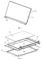
- FIG. 1 is a schematic perspective view of a screen for a laptop computer according to an embodiment of the invention.
- the screen for the laptop computer comprises: a back cover 12 with a liquid crystal screen being mounted therein (not shown); a cover plate 11 for covering the front of the back cover to entirely cover components in the back cover 12 so that a side frame of the screen will not be directly exposed from the front of the screen; and a pivot shaft 14 mounted at the bottom part of the back cover 12to connect with a host computer (or mainframe) of the laptop computer.
- At least one part of the cover plate 11 covering the liquid crystal screen is transparent, whereas the part of the cover plate 11 covering the side frame of the screen is opaque, so that user can directly review the contents displayed on the screen with excellent visual appearance at the front part of the screen.
- the entire cover plate can be transparent.
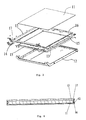
- FIGS 2 and 3 are exploded perspective views of the screen for the laptop computer according to the embodiment of the invention.
- the back cover 12 is constructed as a case with a hollow structure; a fixing body is fixed inside the back cover 12 by screws.
- the fixing body is constructed as a fixing frame 16; a liquid crystal screen 13 is mounted in the fixing frame 16 of the embodiment by screws; and a cover plate 11 is received on a fixing frame 16 of the embodiment and entirely covering the liquid crystal screen 13 and the fixing frame 16.
- the back cover 12 is provided with a pivot shaft 14 connected with the host computer of the laptop computer, and an upper edge of a shaft cover 17 of the pivot shaft is connected with the lower edge of the cover plate 11.
- the material of the cover plate 11 is organic glass (also called acryl (methyl methacrylate)), glass or crystal.
- the screen for a laptop computer having a configuration described above has an integral appearance, which not only protects the screen but also makes the screen appear more neat enhancing visual effect of the screen.
- FIG 4 is a sectional schematic view of the screen for the laptop computer according to the embodiment of the invention.
- the fixing frame in the embodiment of the invention is generally made of plastic, however, the material is not limited thereto.
- at least one supporting member 15 is disposed between the fixing frame and the liquid crystal screen, each supporting member 15 is connected to a side of the liquid crystal screen 13 by screws, and each supporting member 15 further fixed to the fixing frame 16 by screws.
- there are 3 supporting members 15 which are respectively mounted at the left side, right side and lower side of the liquid crystal screen 13.
- the supporting members 15 can be made of metal, such as iron, aluminum alloy and the like.
- the fixing frame can be omitted and the liquid crystal screen is directly mounted to the supporting member fixed to the back cover 12 while achieving the same effect of fixing the liquid crystal screen.
- the cover plate 11 is adhered to the fixing frame 16 by adhesive.
- the connecting manner of the cover plate 11 with the fixing frame 16 can be selected as the following manners:
- a plurality of fixing members 113 are positioned at peripheral edges of the cover plate 11, and frame fixing holes (also called fixing holes for the fixing body) corresponding to the fixing members are also positioned on the fixing frame 16.
- the fixing members 113 are stuck in the frame fixing holes, and the cover plate 11 is fixed to the fixing frame 16.
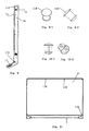
- the fixing member 113 comprises: a base plate 1131, at the back of which the cover plate 11 is connected via adhesive; at least one fixing post 1132, for example, two fixing posts shown in figure 6 , positioned on the base plate 1131, wherein the fixing post comprises a post body and a post head mounted at an end of the post body, and the post head has a truncated cone shape having a diameter larger than that of the post body with the bottom of the post head being a flat plane.
- the post head 1132 is made of rubber, and the post head of the fixing post engages with the frame fixing holes by interference.
- FIG. 7 is a schematic view of the fixing post according to an embodiment of the invention.
- the fixing post is a longitudinal splitting shape with gaps between the split portions. Due to the gaps, each of the split portions can be contracted toward the center so that they can penetrate through the frame fixing holes when mounting and reset after penetration, so that the cover plate 11 and the fixing frame 16 are fixed.
- the fixing posts of the embodiments can use plastic.
- Fixing members are adhered or mounted on the inner surface of the cover plate 11 and the cover plate 11 is fixed to the fixing frame 16 in all of the above connecting manners, so all of the members except for the cover plate 11 hide behind the back face of the transparent plate which makes the surface of the transparent plate more neat.
- Figures 8-11 are a schematic view of another preferred embodiment of the invention.
- a plurality of fixing holes (not shown) for the cover plate are positioned at the edge of the cover plate 11.
- frame fixing holes corresponding to the fixing holes for the cover plate are positioned on the fixing frame 16.
- the cover plate 11 and the fixing frame 16 are fixed through the connecting post 114 passing through the fixing holes for the cover plate and the frame fixing holes.
- the connecting post 114 has a "I" shaped structure with a thinner middle portion and two thicker ends.
- the connecting post 114 is made of rubber, and the post head of the connecting post and the frame fixing holes are interferentially fixed.
- the post heads rebounds to be expanded when inserted by the elasticity of the rubber contracting into the fixing holes so that the frame fixing holes are hooked after mounting in place, thus the cover plate 11 is securely fixed to the fixing frame 16 and it is ensured that the fixing post will not be pulled out easily.
- the post body of the connecting post and an end thereof has a longitudinal splitting shape with gaps between the split portions. Due to the gaps, each of the split portions can be contracted toward the center so that they can penetrate through the frame fixing holes when mounting and reset after penetration, so that the cover plate 11 and the fixing frame 16 are fixed.
- the connecting post can be made of plastic. The appearance of the screen fixed by the connecting post is shown in figure 11 , and a plurality of post heads of the connecting posts 114 can be viewed at the side edge of the cover plate 11.
- FIG 12 is a perspective view according to a preferred embodiment of the invention.
- the screen for the laptop computer besides the above structural components, further comprises a frame 18 which is attached at the back face of the cover plate.
- the frame 18 is a magnetic one whereas the fixing frame 16 is made of iron material.
- the cover plate 11 and the fixing frame 16 are fixed by magnetic attracting force, or the frame 18 can be made of iron material which is attached to the back face of the cover plate whereas the fixing frame 16 is made of magnetic material, and the cover plate 11 and the fixing frame 16 are fixed by magnetic attracting force.
- both of the frame 18 and the fixing frame 16 can be made of magnetic material, however, the corresponding faces have different magnetic poles. According to the principle of opposite poles attracting each other of magnetic material, the cover plate 11 and the fixing frame 16 are fixed by magnetic force.
- the gap between the cover plate 11 and the back cover 12 is filled by sealing material so that dust and moisture are prevented from entering inside the screen. Further, there is a layer of transparent-enhancing film on the outer surface of the cover plate, so that the displaying effect is improved.
- FIG 13 is a perspective view of a laptop computer according to an exemplary embodiment of the invention.
- the laptop computer comprises a mainframe 2 and a screen 1, and the mainframe 2 and the screen 1 are connected by a pivot shaft (not shown in the figure).
- the screen 1 is the one having the cover plate proposed in the exemplary embodiment of the invention, since the structure of the screen are described in detail already, the description thereof is hereby omitted for clarity purpose.
- the laptop computer according to the embodiment of the invention achieves the integration of the screen with the side frame in conventional screen being invisible, which can obtain better visual effects.
- the cover plate provides better protection of the liquid crystal screen, which is more adapted for practical use.
Landscapes
- Engineering & Computer Science (AREA)
- Computer Hardware Design (AREA)
- Theoretical Computer Science (AREA)
- Physics & Mathematics (AREA)
- Human Computer Interaction (AREA)
- General Engineering & Computer Science (AREA)
- General Physics & Mathematics (AREA)
- Mathematical Physics (AREA)
- Devices For Indicating Variable Information By Combining Individual Elements (AREA)
- Liquid Crystal (AREA)
Applications Claiming Priority (1)
| Application Number | Priority Date | Filing Date | Title |
|---|---|---|---|
| CN200720173096.7U CN201035465Y (zh) | 2007-09-12 | 2007-09-12 | 笔记本电脑屏幕以及笔记本电脑 |
Publications (2)
| Publication Number | Publication Date |
|---|---|
| EP2040141A1 true EP2040141A1 (de) | 2009-03-25 |
| EP2040141B1 EP2040141B1 (de) | 2015-01-21 |
Family
ID=39196357
Family Applications (1)
| Application Number | Title | Priority Date | Filing Date |
|---|---|---|---|
| EP08014297.9A Active EP2040141B1 (de) | 2007-09-12 | 2008-08-11 | Bildschirm eines Laptops und Laptop damit |
Country Status (4)
| Country | Link |
|---|---|
| US (1) | US8009415B2 (de) |
| EP (1) | EP2040141B1 (de) |
| CN (1) | CN201035465Y (de) |
| CA (1) | CA2638556C (de) |
Cited By (2)
| Publication number | Priority date | Publication date | Assignee | Title |
|---|---|---|---|---|
| CN102736667A (zh) * | 2011-03-30 | 2012-10-17 | 英业达股份有限公司 | 可携式电子装置 |
| CN104679122A (zh) * | 2013-11-29 | 2015-06-03 | 英业达科技有限公司 | 平板电脑的外接装置 |
Families Citing this family (19)
| Publication number | Priority date | Publication date | Assignee | Title |
|---|---|---|---|---|
| US8687359B2 (en) * | 2008-10-13 | 2014-04-01 | Apple Inc. | Portable computer unified top case |
| JP2012048700A (ja) * | 2010-07-29 | 2012-03-08 | Sony Corp | 情報処理装置 |
| CN102902300B (zh) * | 2011-07-25 | 2015-04-08 | 纬创资通股份有限公司 | 选择性地组装不同尺寸的面板模块的组装结构与面板装置 |
| TWI526074B (zh) * | 2011-09-26 | 2016-03-11 | 仁寶電腦工業股份有限公司 | 顯示裝置及其組裝方法 |
| WO2013063782A1 (en) * | 2011-11-03 | 2013-05-10 | Intel Corporation | Substantially transparent hinged substrate apparatus |
| USD702682S1 (en) * | 2011-11-11 | 2014-04-15 | Shenzhen Dicolor Optoelectronics Co., Ltd. | LED display cabinet |
| TWI513399B (zh) * | 2012-04-04 | 2015-12-11 | Compal Electronics Inc | 顯示裝置 |
| USD709878S1 (en) * | 2012-06-09 | 2014-07-29 | Apple Inc. | Display |
| CN103777683A (zh) * | 2012-10-22 | 2014-05-07 | 苏州辛瑞拉光电科技有限公司 | 电脑周边屏幕保护装置 |
| US10649497B2 (en) | 2014-07-23 | 2020-05-12 | Apple Inc. | Adaptive processes for improving integrity of surfaces |
| WO2016014047A1 (en) * | 2014-07-23 | 2016-01-28 | Apple Inc. | Adaptive processes for improving integrity of surfaces |
| USD768619S1 (en) | 2015-03-06 | 2016-10-11 | Apple Inc. | Display |
| TW201637543A (zh) * | 2015-04-15 | 2016-10-16 | 鴻海精密工業股份有限公司 | 顯示裝置 |
| JP6025228B1 (ja) * | 2015-05-15 | 2016-11-16 | Necプラットフォームズ株式会社 | ディスプレイ装置 |
| TWI585724B (zh) * | 2016-06-28 | 2017-06-01 | 達運精密工業股份有限公司 | 顯示裝置及其框體 |
| CN107272826A (zh) * | 2017-06-28 | 2017-10-20 | 昆山特酷信息科技有限公司 | 笔记本电脑的保护型后盖 |
| CN108874043B (zh) * | 2018-06-29 | 2024-07-23 | 联想(北京)有限公司 | 一种电子设备 |
| CN110580084B (zh) | 2019-08-06 | 2021-10-15 | 华为技术有限公司 | 一种移动终端 |
| CN110825175A (zh) * | 2019-12-10 | 2020-02-21 | 北京小米移动软件有限公司 | 显示屏及笔记本电脑 |
Citations (2)
| Publication number | Priority date | Publication date | Assignee | Title |
|---|---|---|---|---|
| EP1544714A2 (de) * | 2003-12-15 | 2005-06-22 | Fujitsu Limited | Elektronisches Gerät |
| US20050286214A1 (en) * | 2004-06-25 | 2005-12-29 | Asustek Computer Inc. | Electronic device with protection function |
Family Cites Families (26)
| Publication number | Priority date | Publication date | Assignee | Title |
|---|---|---|---|---|
| US5379182A (en) * | 1991-11-29 | 1995-01-03 | Nec Corporation | Hinged display panel with outer cover and display panel unit separately connected to an inner cover and information machine including the same |
| JP3725633B2 (ja) * | 1996-10-21 | 2005-12-14 | 株式会社東芝 | 携帯形機器 |
| JP3296993B2 (ja) * | 1997-04-08 | 2002-07-02 | エルジー フィリップス エルシーディー カンパニー リミテッド | 液晶表示装置を備える携帯用コンピュータ |
| EP0877313B1 (de) * | 1997-05-06 | 2005-12-14 | Samsung Electronics Co., Ltd. | Schwenkbare Vorrichtung und tragbarer Rechner mit schwenkbarer Vorrichtung |
| JPH116998A (ja) * | 1997-06-09 | 1999-01-12 | Internatl Business Mach Corp <Ibm> | 液晶パネル及び液晶表示装置 |
| US6202256B1 (en) * | 1998-09-04 | 2001-03-20 | Compaq Computer Corporation | Hinge system for a portable computer |
| KR100508003B1 (ko) * | 1998-11-11 | 2005-11-21 | 엘지.필립스 엘시디 주식회사 | 휴대용컴퓨터와그평판표시장치의결합방법 |
| US6654078B1 (en) * | 1999-02-18 | 2003-11-25 | Nec Lcd Technologies, Ltd. | Liquid crystal module mounting structure and mobile terminal mounted with the same |
| KR100322651B1 (ko) * | 1999-03-13 | 2002-02-07 | 윤종용 | 디스플레이 유니트 및 그 디스플레이 유니트를 사용한 노트북 컴퓨터 |
| JP2000305066A (ja) * | 1999-04-20 | 2000-11-02 | Nec Yonezawa Ltd | 液晶ディスプレイ固定方法および液晶ディスプレイ固定具 |
| JP3372905B2 (ja) * | 1999-07-15 | 2003-02-04 | 米沢日本電気株式会社 | 液晶モジュール取付け構造 |
| TWI298831B (en) * | 2001-07-10 | 2008-07-11 | Fujitsu Ltd | Plane unit structure, portable computer and display unit(1) |
| JP2003029241A (ja) * | 2001-07-17 | 2003-01-29 | Sony Corp | 液晶表示装置及び情報処理装置 |
| JP3673223B2 (ja) * | 2002-01-21 | 2005-07-20 | 株式会社東芝 | 携帯用情報機器 |
| JP3696210B2 (ja) * | 2003-01-31 | 2005-09-14 | 株式会社東芝 | 電子機器 |
| US7343645B2 (en) * | 2004-04-23 | 2008-03-18 | Asustek Computer Inc. | Electronic apparatus having detachable display and mainframe |
| KR101209317B1 (ko) * | 2004-06-30 | 2012-12-06 | 엘지전자 주식회사 | 힌지조립체 및 이를 구비한 휴대용 컴퓨터 |
| US20060002060A1 (en) * | 2004-07-02 | 2006-01-05 | Alex Ling | Notebook having a display apparatus with changeable shells |
| US20060023407A1 (en) * | 2004-07-27 | 2006-02-02 | Alex Ling | Notebook suitable for display panels of different sizes |
| US20060023404A1 (en) * | 2004-07-27 | 2006-02-02 | Alex Ling | Notebook having a display apparatus with a modularized retaining device |
| TWM263730U (en) * | 2004-08-10 | 2005-05-01 | Au Optronics Corp | A frame structure for a liquid crystal module |
| TWM276250U (en) * | 2005-05-12 | 2005-09-21 | Twinhead Int Corp | Structure for the display module of a portable computer |
| CN1945491A (zh) | 2005-10-09 | 2007-04-11 | 华硕电脑股份有限公司 | 笔记本电脑的显示屏外观结构 |
| CN2909316Y (zh) * | 2006-04-28 | 2007-06-06 | 鸿富锦精密工业(深圳)有限公司 | 液晶显示器 |
| CN2909317Y (zh) * | 2006-05-12 | 2007-06-06 | 鸿富锦精密工业(深圳)有限公司 | 液晶显示器 |
| JP2007328613A (ja) * | 2006-06-08 | 2007-12-20 | Toshiba Corp | 電子機器 |
-
2007
- 2007-09-12 CN CN200720173096.7U patent/CN201035465Y/zh not_active Expired - Lifetime
-
2008
- 2008-08-07 CA CA2638556A patent/CA2638556C/en active Active
- 2008-08-11 EP EP08014297.9A patent/EP2040141B1/de active Active
- 2008-09-11 US US12/208,627 patent/US8009415B2/en active Active - Reinstated
Patent Citations (2)
| Publication number | Priority date | Publication date | Assignee | Title |
|---|---|---|---|---|
| EP1544714A2 (de) * | 2003-12-15 | 2005-06-22 | Fujitsu Limited | Elektronisches Gerät |
| US20050286214A1 (en) * | 2004-06-25 | 2005-12-29 | Asustek Computer Inc. | Electronic device with protection function |
Cited By (2)
| Publication number | Priority date | Publication date | Assignee | Title |
|---|---|---|---|---|
| CN102736667A (zh) * | 2011-03-30 | 2012-10-17 | 英业达股份有限公司 | 可携式电子装置 |
| CN104679122A (zh) * | 2013-11-29 | 2015-06-03 | 英业达科技有限公司 | 平板电脑的外接装置 |
Also Published As
| Publication number | Publication date |
|---|---|
| US8009415B2 (en) | 2011-08-30 |
| CA2638556A1 (en) | 2009-03-12 |
| EP2040141B1 (de) | 2015-01-21 |
| CN201035465Y (zh) | 2008-03-12 |
| CA2638556C (en) | 2014-03-25 |
| US20090067125A1 (en) | 2009-03-12 |
Similar Documents
| Publication | Publication Date | Title |
|---|---|---|
| US8009415B2 (en) | Screen of laptop computer and laptop computer having the same | |
| USD523442S1 (en) | Computer generated image for a display panel or screen | |
| USD618250S1 (en) | Computer generated image for a display panel or screen | |
| USD423483S (en) | Modal window for a computer display screen | |
| USD559258S1 (en) | User interface for computer display | |
| USD426525S (en) | Window for a computer display screen | |
| WO2016183998A1 (zh) | 移动终端显示结构及移动终端 | |
| KR20180079091A (ko) | 폴더블 표시 장치 | |
| USD406122S (en) | Set of windows for a computer display screen | |
| CN116013160B (zh) | 显示模组及其制备方法、电子设备 | |
| EP4221163A1 (de) | Elektronische vorrichtung | |
| US9795068B2 (en) | Electronic device | |
| CN216280532U (zh) | 一种裸眼3d显示屏 | |
| US20220132046A1 (en) | Apparatus Utilizing and Method of Partial Lamination for a Seamless Interface with Touchscreen Functionality | |
| KR200474675Y1 (ko) | 모니터용 메모지 부착보드 | |
| USD433392S (en) | Window for a computer display screen | |
| US7089696B1 (en) | Document displaying system | |
| CN201749697U (zh) | 外挂式液晶显示器防护罩 | |
| CN200956690Y (zh) | 便携保护盒体 | |
| CN210270442U (zh) | Lcd液晶显示屏360度全方位立体防护结构 | |
| CN212782589U (zh) | 一种便携式防摔显示器 | |
| USD424039S (en) | Window for a computer display screen | |
| CN219916127U (zh) | 液晶显示屏 | |
| CN110700518A (zh) | 可拆卸阳角护板及其装配方法 | |
| CN110187743B (zh) | 一种能单手持握的平板电脑结构 |
Legal Events
| Date | Code | Title | Description |
|---|---|---|---|
| PUAI | Public reference made under article 153(3) epc to a published international application that has entered the european phase |
Free format text: ORIGINAL CODE: 0009012 |
|
| 17P | Request for examination filed |
Effective date: 20080811 |
|
| AK | Designated contracting states |
Kind code of ref document: A1 Designated state(s): AT BE BG CH CY CZ DE DK EE ES FI FR GB GR HR HU IE IS IT LI LT LU LV MC MT NL NO PL PT RO SE SI SK TR |
|
| AX | Request for extension of the european patent |
Extension state: AL BA MK RS |
|
| 17Q | First examination report despatched |
Effective date: 20091014 |
|
| AKX | Designation fees paid |
Designated state(s): DE FR GB |
|
| GRAP | Despatch of communication of intention to grant a patent |
Free format text: ORIGINAL CODE: EPIDOSNIGR1 |
|
| INTG | Intention to grant announced |
Effective date: 20141015 |
|
| RIN1 | Information on inventor provided before grant (corrected) |
Inventor name: CHEN, XING Inventor name: DONG, HUAJUN Inventor name: XIA, XIAOSONG Inventor name: HE, XIUFENG |
|
| GRAS | Grant fee paid |
Free format text: ORIGINAL CODE: EPIDOSNIGR3 |
|
| GRAA | (expected) grant |
Free format text: ORIGINAL CODE: 0009210 |
|
| AK | Designated contracting states |
Kind code of ref document: B1 Designated state(s): DE FR GB |
|
| REG | Reference to a national code |
Ref country code: GB Ref legal event code: FG4D |
|
| REG | Reference to a national code |
Ref country code: DE Ref legal event code: R096 Ref document number: 602008036420 Country of ref document: DE Effective date: 20150305 |
|
| REG | Reference to a national code |
Ref country code: DE Ref legal event code: R097 Ref document number: 602008036420 Country of ref document: DE |
|
| REG | Reference to a national code |
Ref country code: FR Ref legal event code: PLFP Year of fee payment: 8 |
|
| PLBE | No opposition filed within time limit |
Free format text: ORIGINAL CODE: 0009261 |
|
| STAA | Information on the status of an ep patent application or granted ep patent |
Free format text: STATUS: NO OPPOSITION FILED WITHIN TIME LIMIT |
|
| 26N | No opposition filed |
Effective date: 20151022 |
|
| REG | Reference to a national code |
Ref country code: FR Ref legal event code: PLFP Year of fee payment: 9 |
|
| REG | Reference to a national code |
Ref country code: FR Ref legal event code: PLFP Year of fee payment: 9 |
|
| REG | Reference to a national code |
Ref country code: FR Ref legal event code: PLFP Year of fee payment: 10 |
|
| REG | Reference to a national code |
Ref country code: FR Ref legal event code: PLFP Year of fee payment: 11 |
|
| P01 | Opt-out of the competence of the unified patent court (upc) registered |
Effective date: 20230627 |
|
| PGFP | Annual fee paid to national office [announced via postgrant information from national office to epo] |
Ref country code: DE Payment date: 20250827 Year of fee payment: 18 |
|
| PGFP | Annual fee paid to national office [announced via postgrant information from national office to epo] |
Ref country code: GB Payment date: 20250826 Year of fee payment: 18 |
|
| PGFP | Annual fee paid to national office [announced via postgrant information from national office to epo] |
Ref country code: FR Payment date: 20250825 Year of fee payment: 18 |