EP2040159A2 - Processeur et interface - Google Patents
Processeur et interface Download PDFInfo
- Publication number
- EP2040159A2 EP2040159A2 EP08016826A EP08016826A EP2040159A2 EP 2040159 A2 EP2040159 A2 EP 2040159A2 EP 08016826 A EP08016826 A EP 08016826A EP 08016826 A EP08016826 A EP 08016826A EP 2040159 A2 EP2040159 A2 EP 2040159A2
- Authority
- EP
- European Patent Office
- Prior art keywords
- processor
- sif
- interface
- data
- bit
- Prior art date
- Legal status (The legal status is an assumption and is not a legal conclusion. Google has not performed a legal analysis and makes no representation as to the accuracy of the status listed.)
- Ceased
Links
Images
































Classifications
-
- G—PHYSICS
- G06—COMPUTING OR CALCULATING; COUNTING
- G06F—ELECTRIC DIGITAL DATA PROCESSING
- G06F1/00—Details not covered by groups G06F3/00 - G06F13/00 and G06F21/00
- G06F1/24—Resetting means
-
- G—PHYSICS
- G06—COMPUTING OR CALCULATING; COUNTING
- G06F—ELECTRIC DIGITAL DATA PROCESSING
- G06F11/00—Error detection; Error correction; Monitoring
- G06F11/07—Responding to the occurrence of a fault, e.g. fault tolerance
- G06F11/08—Error detection or correction by redundancy in data representation, e.g. by using checking codes
- G06F11/10—Adding special bits or symbols to the coded information, e.g. parity check, casting out 9's or 11's
-
- G—PHYSICS
- G06—COMPUTING OR CALCULATING; COUNTING
- G06F—ELECTRIC DIGITAL DATA PROCESSING
- G06F15/00—Digital computers in general; Data processing equipment in general
- G06F15/16—Combinations of two or more digital computers each having at least an arithmetic unit, a program unit and a register, e.g. for a simultaneous processing of several programs
- G06F15/163—Interprocessor communication
- G06F15/173—Interprocessor communication using an interconnection network, e.g. matrix, shuffle, pyramid, star, snowflake
- G06F15/17337—Direct connection machines, e.g. completely connected computers, point to point communication networks
-
- G—PHYSICS
- G06—COMPUTING OR CALCULATING; COUNTING
- G06F—ELECTRIC DIGITAL DATA PROCESSING
- G06F8/00—Arrangements for software engineering
- G06F8/40—Transformation of program code
- G06F8/41—Compilation
- G06F8/44—Encoding
- G06F8/443—Optimisation
- G06F8/4434—Reducing the memory space required by the program code
-
- G—PHYSICS
- G06—COMPUTING OR CALCULATING; COUNTING
- G06F—ELECTRIC DIGITAL DATA PROCESSING
- G06F9/00—Arrangements for program control, e.g. control units
- G06F9/06—Arrangements for program control, e.g. control units using stored programs, i.e. using an internal store of processing equipment to receive or retain programs
- G06F9/30—Arrangements for executing machine instructions, e.g. instruction decode
- G06F9/30003—Arrangements for executing specific machine instructions
- G06F9/30007—Arrangements for executing specific machine instructions to perform operations on data operands
- G06F9/30032—Movement instructions, e.g. MOVE, SHIFT, ROTATE, SHUFFLE
-
- G—PHYSICS
- G06—COMPUTING OR CALCULATING; COUNTING
- G06F—ELECTRIC DIGITAL DATA PROCESSING
- G06F9/00—Arrangements for program control, e.g. control units
- G06F9/06—Arrangements for program control, e.g. control units using stored programs, i.e. using an internal store of processing equipment to receive or retain programs
- G06F9/30—Arrangements for executing machine instructions, e.g. instruction decode
- G06F9/30003—Arrangements for executing specific machine instructions
- G06F9/3004—Arrangements for executing specific machine instructions to perform operations on memory
-
- G—PHYSICS
- G06—COMPUTING OR CALCULATING; COUNTING
- G06F—ELECTRIC DIGITAL DATA PROCESSING
- G06F9/00—Arrangements for program control, e.g. control units
- G06F9/06—Arrangements for program control, e.g. control units using stored programs, i.e. using an internal store of processing equipment to receive or retain programs
- G06F9/30—Arrangements for executing machine instructions, e.g. instruction decode
- G06F9/30145—Instruction analysis, e.g. decoding, instruction word fields
-
- G—PHYSICS
- G06—COMPUTING OR CALCULATING; COUNTING
- G06F—ELECTRIC DIGITAL DATA PROCESSING
- G06F9/00—Arrangements for program control, e.g. control units
- G06F9/06—Arrangements for program control, e.g. control units using stored programs, i.e. using an internal store of processing equipment to receive or retain programs
- G06F9/30—Arrangements for executing machine instructions, e.g. instruction decode
- G06F9/30145—Instruction analysis, e.g. decoding, instruction word fields
- G06F9/30149—Instruction analysis, e.g. decoding, instruction word fields of variable length instructions
-
- G—PHYSICS
- G06—COMPUTING OR CALCULATING; COUNTING
- G06F—ELECTRIC DIGITAL DATA PROCESSING
- G06F9/00—Arrangements for program control, e.g. control units
- G06F9/06—Arrangements for program control, e.g. control units using stored programs, i.e. using an internal store of processing equipment to receive or retain programs
- G06F9/30—Arrangements for executing machine instructions, e.g. instruction decode
- G06F9/30145—Instruction analysis, e.g. decoding, instruction word fields
- G06F9/3016—Decoding the operand specifier, e.g. specifier format
- G06F9/30167—Decoding the operand specifier, e.g. specifier format of immediate specifier, e.g. constants
-
- G—PHYSICS
- G06—COMPUTING OR CALCULATING; COUNTING
- G06F—ELECTRIC DIGITAL DATA PROCESSING
- G06F9/00—Arrangements for program control, e.g. control units
- G06F9/06—Arrangements for program control, e.g. control units using stored programs, i.e. using an internal store of processing equipment to receive or retain programs
- G06F9/30—Arrangements for executing machine instructions, e.g. instruction decode
- G06F9/32—Address formation of the next instruction, e.g. by incrementing the instruction counter
- G06F9/322—Address formation of the next instruction, e.g. by incrementing the instruction counter for non-sequential address
- G06F9/324—Address formation of the next instruction, e.g. by incrementing the instruction counter for non-sequential address using program counter relative addressing
Definitions
- the present invention relates to a processor, to an interface - in particular a serial interface - associated with the processor, and to methods of operation of the processor and the interface.
- the invention also relates to an instruction set and to methods of programming operation of the processors and the interface.
- the invention also relates to a data processing apparatus.
- the invention also relates to a family of processors.
- a data processing apparatus comprising:
- said master circuitry comprises a processor or a hardware state machine.
- a parallel interface is provided between said master circuitry and said interface circuit and a serial interface is provided for connecting the interface circuit to said external apparatus.
- the master circuitry is provided on the same integrated circuit as the processor.
- the integrated circuit is in the form of an Application Specific Integrated Circuit (ASIC) or a Field Programmable Gate Array (FPGA).
- ASIC Application Specific Integrated Circuit
- FPGA Field Programmable Gate Array
- a request for access received from an external apparatus takes precedence over a request for access received from the master circuitry.
- said processor and interface circuit are provided on a single integrated circuit.
- the data processing apparatus further comprises a plurality of processors each constructed to operate under control of a stored program comprising a sequence of program instructions selected from a predetermined instruction set, and wherein the interface circuit is provided in common to said plurality of processors and is operable to provide an interface for an external apparatus or said master circuitry to signal a request for access to storage locations of the plurality of processors.
- said request includes:
- said request includes a status field and wherein said interface circuit is operable to use said status field for reporting status information to said external apparatus or said master circuitry.
- the apparatus further comprises a controller operable, in response to interrogation from said external apparatus or said master circuitry, to output data to said external apparatus identifying register lengths of said apparatus.
- the data processing apparatus further comprises a controller operable to control input and output to and from the interface circuit and operable to generate odd parity over an even number of bits to allow the identification by said external apparatus or said master circuitry if an input or an output of said interface circuit is stuck at a logic low or a logic high signal.
- a controller operable to control input and output to and from the interface circuit and operable to generate odd parity over an even number of bits to allow the identification by said external apparatus or said master circuitry if an input or an output of said interface circuit is stuck at a logic low or a logic high signal.
- the interface circuit is operable to provide an interface for an external apparatus or the master circuitry to signal a request to control the processor.
- said request to control the data processing apparatus is operable to cause at least a portion of the data processing apparatus to reset
- said request is operable to cause said interface circuit to reset
- said request is operable to cause said processor to reset
- the data processing apparatus further comprises at least one counter for maintaining counts relating to the operation of the interface circuit, wherein in response to receiving a request for a count held by at least one of said at least one counter, said interface circuit is operable to read the value of said at least one counter and to output the value to said external apparatus or said master circuitry.
- counters are provided to count at least one of: the number of data reads requested by one of the external apparatus and the master circuitry; the number of data writes requested by one of the external apparatus and the master circuitry; the number of errors; and the number of cancelled requests that have been made by one of the external apparatus and the master circuitry.
- the interface circuit is operable to provide an interface for an external apparatus to signal a request to control the data processing apparatus, wherein pending requests are stored in said interface circuit, and wherein the apparatus further comprises a control circuit operable to cancel a pending request upon receipt of a cancel request from said external apparatus.
- the apparatus further comprises master circuitry operable to request access to storage locations of said processor via said interface circuit and wherein said control circuit is operable to cancel a request from said master circuitry upon receipt of said cancel request from said external apparatus.
- the interface circuit is operable to provide an interface for an external apparatus to signal a request for data from a storage location of the processor, and wherein the apparatus further comprises a controller operable to cause the data to be read from the storage location, the controller being further operable to generate a time stamp indicating a time at which the data was read from said storage location and operable to cause said read data and said time stamp to be output to said external device.
- the data processing apparatus further comprises acquisition circuitry operable to acquire signals from an analogue input; and a controller operable to prevent output of signals to said external apparatus at a time that said acquisition circuitry is acquiring said signals from said analogue input
- said controller comprises a hardware circuit which is operable to enable and disable output of signals from said interface circuit to said external apparatus.
- said controller is defined by at least one of said instructions that control the operation of said processor, such that upon execution of a specific instruction allows said interface circuit to provide said external apparatus with access to said storage location.
- a data processing apparatus comprising:
- said request includes:
- said request includes a status field and wherein said interface circuit is operable to use said status field for reporting status information to said external apparatus.
- the apparatus comprises a controller operable, in response to interrogation from an external apparatus, to output data to said external apparatus identifying register lengths of said apparatus and identifying the number of processors coupled in common to said interface circuit.
- a processor which comprises an instruction set for execution on the processor, a processor architecture and a memory, wherein the instruction set and the processor architecture comprise characteristics which have been specifically tailored to ensure that the code density compiled for execution at least in part on the processor memory is relatively high.
- the instruction set comprises lower level (assembler/processor) programming language instructions tailored to the characteristics of higher level programming language functions.
- the lower level instructions are tailored based on the calling conventions of the functions.
- the functions are those for which tailored instructions would lead to higher compiled code density than if the instructions were not tailored.
- the lower level instructions are tailored to the characteristics of the higher level language compiler.
- the instruction set comprises lower level (assembler/processor) programming language instructions which are adapted to operate in accordance with a particular compiler calling convention thereby to improve compiled code density.
- lower level assembly/processor
- the processor is in the form of a reduced instruction set (RISC) processor.
- RISC reduced instruction set
- the lower level instructions are complex instructions.
- the lower level instructions enable function calls in the higher level language to be handled more efficiently.
- the lower level instructions enable function returns in the higher level language to be handled more efficiently.
- the processor comprises at least one processor register, and wherein the use characteristics of this register vary depending on which particular lower level instruction makes use of the register.
- the processor comprises at least two sets of processor registers having use characteristics which are dependent on the particular lower level instructions making use of such register sets, and which have different characteristics to one another.
- the number of the registers is dependent on the size of the processor.
- the lower level instructions operate on multiple processor registers simultaneously.
- the lower level instructions are used for moving variables between various processor registers.
- the lower level instructions are used for setting up various processor registers upon a higher level language function call.
- the lower level instructions are used for restoring various processor registers upon a higher level language function return.
- At least one lower level instruction is adapted to move and/or copy multiple registers and/or immediates into a particular set of registers upon execution of the instruction.
- At least one lower level instruction is adapted to move and/or copy multiple registers onto a memory stack upon execution of the instruction.
- At least one lower level instruction is adapted to move and/or copy multiple registers from a memory stack into a particular set of registers upon execution of the instruction.
- At least one lower level instruction is adapted to move and/or copy multiple registers from a first particular set of registers to a second particular set of registers upon execution of the instruction.
- the lower level instructions are each executed within a single instruction cycle.
- the lower level instructions are compound instructions adapted to carry out a plurality of actions.
- At least some instructions in the instruction set are provided in a variety of sizes, and wherein the size of instruction which is to be used is adapted only to be determined on an instruction by instruction basis during code assembly.
- equivalent instructions are provided in both short and long coding formats.
- instructions which are used frequently and which can be coded in a short coding format are provided in a short coding format.
- the short coding format is a 16 bit coding format
- the long coding format is a 32 bit coding format
- the processor memory includes at least two instruction spaces, a first instruction space having instructions which are longer than those in the second instruction space.
- the first instruction space is a 32 bit instruction space
- the second instruction space is a 16 bit instruction space.
- the first instruction space is larger than the second instruction space.
- the first instruction space overlaps the second instruction space.
- each instruction comprises at least one instruction size bit to indicate the instruction size.
- the instruction size bit is provided in the lowest byte, and wherein the processor comprises a little endian architecture.
- the instruction size bit is provided in the highest byte, and wherein the processor comprises a big endian architecture.
- more than one instruction size bit is provided in each instruction to indicate the instruction size.
- the ratio of smaller instructions to larger instructions is related to the number of instruction size bits.
- At least some of the instructions in the instruction set are adapted to write to and/or read from any adjacent processor register pair.
- a processor which comprises an instruction set for execution on the processor, a processor architecture and a memory, wherein at least some of the instructions in the instruction set are adapted to write to and/or read from any adjacent processor register pair.
- the instructions are able to write to and/or read from unaligned register pairs.
- the instructions are able to write to and/or read from aligned register pairs.
- the instructions are able to write to and/or read from any adjacent register pair within a single program instruction cycle.
- At least some of the instructions in the instruction set are adapted to operate on operands and/or immediates specified within such instructions, and wherein these operands or immediates comprise an odd number of bits.
- a processor which comprises an instruction set for execution on the processor, a processor architecture and a memory, wherein at least some of the instructions in the instruction set are adapted to operate on operands and/or immediates specified within such instructions, and wherein these operands or immediates comprise an odd number of bits.
- the operands or immediates comprise 4*n+1 numbers of bits, where n is an integer number.
- the operands or immediates comprise any of the following numbers of bits: 5, 9, 13, 17, 21, 23 or 25.
- At least some of the instructions are further adapted to make use of at least one of the bits in the operand or immediate to modify a result of the executed instruction.
- At least some of the instructions are further adapted to operate on a 17 bit immediate or operand and use the 17 th bit in the immediate to modify the result of the execute instruction.
- the instruction set comprises a lower level instruction adapted to copy the contents of a particular processor register to a plurality of further registers.
- a processor which comprises an instruction set for execution on the processor, a processor architecture and a memory, wherein the instruction set comprises a lower level instruction which is adapted to copy the contents of a particular processor register to a plurality of further registers.
- the instruction is adapted to execute within a single programming instruction cycle.
- the processor comprises a lower level instruction adapted to address a memory location, and wherein the address is at least in part formed with the use of an operand or immediate which is adapted to be passed to the instruction.
- a processor which comprises an instruction set for execution on the processor, a processor architecture and a memory, wherein the instruction set comprises a lower level instruction adapted to address a memory location, and wherein the address is at least in part formed with the use of an operand or immediate which is adapted to be passed to the instruction.
- the operand or immediate is at least 23 bits in length.
- the operand or immediate is at least 25 bits in length.
- the immediate is added to a global pointer, which is adapted to address a memory location in a random access memory (RAM) which is connectable to the processor.
- RAM random access memory
- the immediate is added to a program counter, which is adapted to address a memory location in a flash memory which is connectable to the processor.
- the processor comprises an instruction which is adapted to multiply two values together and then to normalise the result within a single instruction cycle.
- a processor which comprises an instruction set for execution on the processor, a processor architecture and a memory, wherein the instruction set comprises an instruction which is adapted to multiply two values together and then to normalise the result within a single instruction cycle.
- an intermediate value resulting from the multiplication step is not adapted to be stored in a separate processor register.
- the instruction is adapted to multiply together two 32 bit numbers, thereby to form a 64 bit number and to select any contiguous block of 32 bits from within the 64 bit number thereby to normalise the 64 bit number.
- the instruction is adapted to multiply together two 16 bit numbers, thereby to form a 32 bit number and to select any contiguous block of 16 bits from within the 32 bit number thereby to normalise the 32 bit number.
- the processor comprises means for halting operation of the processor execution in dependence on a particular set of characteristics being met a selectable number of times.
- a processor which comprises an instruction set for execution on the processor, a processor architecture and a memory, and means for halting operation of the processor execution in dependence on a particular set of characteristics being met a particular number of times.
- the halting means is adapted to enable debugging of program code which is executable on the processor.
- the halting means forms part of the processor core.
- the set of characteristics may be selected from any one of the following: the addressing of a particular processor register; the writing of data; and a particular data value.
- an electronic device comprising an application specific integrated circuit which incorporates a processor as herein described.
- a compiler having certain calling conventions and instruction set and processor programming model characteristics which are adapted to enable the compiler to compile program code for execution on a processor as herein described.
- the or each integrated circuit comprises an interface circuit which is operable i) to provide an interface for a control pod to signal a request for access to storage locations of the processor; and ii) to provide parity checking for said access which provides odd parity over an even number of bits.
- said master computer is operable to interact with any of said processors by issuing a reset instruction.
- said reset instruction is operable to reset a portion of a selected one of the integrated circuits.
- said portion is one or more of a selected processor; an interface circuit that provides access to the processor; off-chip circuitry; and on-chip circuitry.
- said master computer is operable to interact with any of said processors by issuing a cancel instruction of a previous instruction issued by the master computer or issued by circuitry internal to said integrated chip.
- said master computer is operable to request data from or to send data to one or more of said processors and wherein said one or more processors are operable to output a time stamp indicating when the data is read or written to or from memory in or connected to the integrated circuit.
- said master computer is operable to transmit a query command to said integrated circuit and wherein said integrated circuit is operable to output a response identifying register sizes and processor numbers in said integrated circuit
- said control pod is operable to receive plural data segments from said interface circuit and is operable to collate the data fragments and to send them to said master computer in a single data packet
- said control pod is operable: i) to receive data from said master computer; ii) to fragment the data into a plurality of smaller data fragments; and iii) to transmit said smaller data fragments one at a time to an integrated circuit
- a data processing apparatus comprising:
- said request includes:
- said request includes a status field and wherein said interface circuit is operable to use said status field for reporting status information to said external apparatus.
- the apparatus comprises a controller operable, in response to interrogation from an external apparatus, to output data to said external apparatus identifying register lengths of said apparatus and identifying the number of processors coupled in common to said interface circuit
- a data processing apparatus comprising:
- said master circuitry comprises a processor or a hardware state machine.
- a parallel interface is provided between said master circuitry and said interface circuit and a serial interface is provided for connecting the interface circuit to said external apparatus.
- a data processing apparatus comprising:
- a data processing apparatus comprising:
- said request is operable to cause said interface circuit to reset.
- said request is operable to cause said processor to reset.
- a data processing apparatus comprising:
- counters are provided to count one or more of the number of data reads requested by the external apparatus; the number of data writes requested by the external apparatus; the number of errors; and the number of cancelled requests that have been made by the external apparatus.
- a data processing apparatus comprising:
- the apparatus further comprises master circuitry operable to request access to storage locations of said processor via said interface circuit and wherein said control circuit is operable to cancel a request from said master circuitry upon receipt of said cancel request from said external apparatus.
- a data processing apparatus comprising:
- a data processing apparatus comprising:
- said controller comprises a hardware circuit which is operable to enable and disable output of signals from said interface circuit to said external apparatus.
- said controller is defined by one or more of said instructions that control the operation of said processor, such that upon execution of a specific instruction allows said interface circuit to provide said external apparatus with access to said storage location.
- a data processing apparatus comprising:
- the apparatus further comprises control means operable to provide access between a specified storage location and the interface circuit in response to such a request only at predetermined points in the execution of the stored program by said processor, said control means being operable to fix periods of time for providing such access relative to the sequence of program instruction such that execution timing of the stored instructions is independent of whether or not such a communication request is supplied to said circuit by said external apparatus.
- control means operable to provide access between a specified storage location and the interface circuit in response to such a request only at predetermined points in the execution of the stored program by said processor, said control means being operable to fix periods of time for providing such access relative to the sequence of program instruction such that execution timing of the stored instructions is independent of whether or not such a communication request is supplied to said circuit by said external apparatus.
- said control means comprises a generic communication instruction of the instruction set, the generic communication instruction having a fixed execution time by said processor.
- said processor and interface circuit are provided on a single integrated circuit
- said interface circuit provides a serial interface to said external apparatus.
- said serial interface includes separate data lines for input and output of data to the interface circuit
- said serial interface includes a clock line for synchronising said data input and output asynchronously with respect to operation of said processor.
- the communication request includes a specific communication instruction loaded by the external apparatus into an interface register of the interface circuit, and wherein the control means is operable to provide access between the specified storage location and the interface register under control of the specific communication instruction.
- the interface circuit includes at least one control line which has an active state which is setable by either of the interface circuit and the external apparatus, wherein said external apparatus is operable to signal said request for access by setting the active state of said at least one control line, wherein said interface circuit is operable to detect the setting of said active state of said at least one control line by said external apparatus and to maintain the active state on said at least one control line until access has been provided between the specified storage location and the interface circuit during one of said periods of time and wherein said interface circuit is operable to release said control line when it is ready to receive a subsequent communication request.
- said processor is operable to load said information into the interface register of the interface circuit during said time period, before the interface circuit releases the control line, which allows said information to be read from the interface register by the external apparatus.
- the apparatus further comprises circuitry which is operable to interpret the specific communication instructions in accordance with pre-determined rules.
- said specific communication instruction includes an address field which is interpreted by the processor as specifying said storage location within a storage space of the processor, and wherein the control means is responsive to the specific communication instruction during said time period to allow reading, writing or a selection of reading and writing to be performed between the interface circuit and the specified storage location.
- said storage space comprises data memory space, register space, and/or program memory of the processor.
- said external apparatus is operable to select a reading or writing operation within the processor under control of a selection field in the specific communication instruction loaded into the interface register.
- said interface register is a shift register which is loadable bit-serially under control of said external apparatus.
- the processor is responsive to a predetermined external signal so as to enter a state in which program controlled operation of the processor is suspended, and wherein said control means is responsive to received communication requests to provide said access at any time during said suspended state.
- the apparatus further comprises mixed analogue and digital signal processing circuitry integrated with said processor in a single integrated circuit
- a family of processors which share a number of common characteristics, and in which substantially the only differences between the processors are as a result of the different sizes thereof.
- a processor forming part of a family of similar processors each having a number of common characteristics, and in which the only differences between the processors and the other processors in the family are as a result of the different sizes of the processors.
- the processors are similar in that they share one or more of the characteristics listed in Table 1 below. More preferably, each of the processors is unique in accordance with one or more of the parameters listed in Table I below.
- a data processing apparatus including one or more processors, each processor having associated memory, registers and debug instructions, and an interface capable of communicating with the or each processor, wherein the interface provides non-invasive access to the or each processor memory, registers or debug instructions.
- the data processing apparatus is implemented in a single semiconductor device or chip, which contains one interface and one or more processors.
- the processors are preferably slaves to the interface. More preferably, the processors form part of the family of processors as hereinbefore described.
- semiconductor device as used herein is preferably intended to connote an ASIC or FPGA implemented in silicon or germanium or gallium-arsenide or some other semiconductor material.
- the semiconductor device is also referred to as a chip.
- SIF Serial Interface
- high code density refers to the size of the compiled program. Thus, for the same original (high level) program code a smaller sized compiled program will have a higher code density than a larger sized complied program.
- XAP3, XAP4 and XAP5 refer to a number of closely related processors.
- the processors are optimised for embedded use in ASICs and FPGAs. More preferably, the processors may be of different sizes.
- the interface is optimised for embedded use in ASICs and FPGAs.
- the interface which is also referred to as a SIF interface, can support an off-chip master and an on-chip master.
- the off-chip master uses an external (xSIF) interface.
- the on-chip master uses an internal (iSIF) interface.
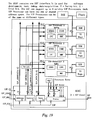
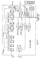
- the interface may be controlled, and hence provide access to the processor's memory, registers and debug instructions provided, either via an external source (using an off-chip master), or via an on-chip device, such as a further processor. Further details in this regard can be found in figures 1 , 2 , 31 and 32 .
- the masters can read and write the registers and memory of one or more on-chip processors. More preferably, the masters can also issue debug instructions to one or more on-chip processors.
- the external interface is a serial interface.
- the internal interface is a parallel interface.
- the interface comprises arbitration hardware for ensuring that communication bandwidth is shared between the internal and external masters.
- processors are those described in table 1.
- TABLE 1 Processor Features Processor 1 (XAP3) Processor 2 (XAP4) Processor 3 (XAP5) Preferred Memory Width 32 bit 16 bit 16 bit Data Bus 32 bit 16 bit 16 bit Address Bus 32 bit 16 bit 24 bit Memory limit 4GB 64 kB 16MB Memory Organisation Little Endian Little Endian Little Endian Instructions 16 bit - 50% 32 bit - 50% 16 bit-87.5% 32 bit-12.5% 16 bit-87.5% 32 bit-12.5% xSIF Shift Register 88 bit 52 bit 84 bit iSIF Registers Address, Control, Data, Status 32, 8, 32,16 bit 16,8,16,12 bit 24, 8, 32, 20 bit Processor Modes 4 4 4 4 User Registers 16 * 32 bit, R0-R15 8 * 16 bit, R0-R7 8 * 16 bit, R0-R7 Stack Pointer R15 R7 Dedicated 24 bit SP Link Register R14 R6 Dedicated 24 bit LR Program Counter Dedicated 32 bit PC Dedicated 16 bit PC Dedicated 24 bit PC Breakpoint Registers
- each of the processors in the family also share the following common features: the processors may all be Load-Store RISC processors; the processors may all support unaligned byte addressing; the processors may all have a Von Neumann architecture (having a single memory and/or memory bus for code and data); the processors may all be implemented in a synthesisable Verilog RTL (Register Transfer Level) language; the processors may all be optimised for code density so that a given program written in, for example C will compile to be as small as possible (giving lower cost and power consumption, while running at a faster speed); the processors may all have a mixture of 16 and 32 bit instructions. Preferably, these instructions can be freely mixed and are evaluated on an instruction by instruction basis.
- a user does not have to specify whether to use a 16 or 32 bit instruction at the time of coding; the processors may all use the same style of instruction mnemonics; the processors may all have the same 4 processor modes: User, Supervisor, Interrupt, Non-Maskable Interrupt (NMI); the processors may all use a SIF interface for software debugging and data acquisition.
- NMI Non-Maskable Interrupt
- the SIF interface supports an internal parallel iSIF interface and an external serial xSIF interface; the processors may all use the same developer environment for software development
- the developer environment comprises the xIDE Toolkits; the processors may all have GCC (GNU Compiler Collection) compilers; the compilers and instruction sets for use with the processors may all be developed together for compatibility and optimal code density; the processors may have good hardware support for embedded operating systems.
- GCC GPU Compiler Collection
- all code for these processors will be in C or another high-level language.
- the code will normally use 8, 16 and 32 bit fixed-point data.
- the code will not normally use floating-point data.
- Some of this code will be custom developed for the application, but much will be off-the-shelf standard product software.
- the family of processors (XAP3, XAP4 and XAP5) all have good features for porting 3 rd -party software.
- processors (XAP3, XAP4 and XAP5) all have many aspects in common. This 'family' approach makes it possible for programmers easily to migrate code from one processor to another. It also makes it easy for programmers acquainted with one processor to learn how to use another processor in the family. These advantages are achieved because of the consistent philosophy applied across all the processors in the family.
- the programmer will typically choose a particular processor based upon: required software size; speed requirements; cost (size of processor and memory) requirements; and power-consumption requirements.
- the XAP4 processor is the smallest in size.
- the XAP3 processor is the largest, and the XAP5 processor is medium-sized.
- a key feature of all the processors is good code density for compiled C code. In all cases this is achieved by instruction sets that are a mixture of 16 and 32 bit: some instructions are only available as 16 bit; some instructions are only available as 32 bit; and some instructions are available in 16 bit and in 32 bit form.
- the instruction mnemonics do not indicate whether an instruction is 16 or 32 bit
- the programmer and compiler do not need to be aware of whether instructions are 16 or 32 bit Only the assembler has to choose between 16 or 32 bit encodings for a particular instruction. This is much more convenient for the programmer as he always has access to all of the processor and all of the instructions (some processors have modes which only allow the programmer to access a subset of the processor's hardware and instructions).
- the 16 and 32 bit instructions can be freely mixed and are evaluated by the hardware at run-time. This may provide good code-density while retaining a friendly programming interface.
- XAP3 and XAP4 are closely related, since they cover a family of closely related processors and an associated interface. Therefore, any, some and/or all features in one aspect may be applied to any, some and/or all features in the other aspect, in any appropriate combination.
- the SIF processor interface system is used in relation to a number of processors, including the XAP3.
- a SIF Computer transfers data to and from one or more SIF Slaves via one or more SIF Pods.
- the SIF Slave is normally an integrated circuit.
- SIF technology includes elements of the SIF inside the integrated circuit and external SIF elements found in the SIF Computer and SIF Pods.
- the XAP3 and SIF Slave module are normally implemented together in the same integrated circuit
- the integrated circuit may also contain other circuit elements.
- the integrated circuit may contain more than one processor, but normally contains just one SIF Slave module.
- the XAP3 is a 32-bit processor that may be implemented in an integrated circuit.
- the integrated circuit may be a standard component or an Application Specific Integrated Circuit (ASIC) or a Field Programmable Gate Array (FPGA).
- ASIC Application Specific Integrated Circuit
- FPGA Field Programmable Gate Array
- the same width is used for data, registers and address and instruction, in accordance with good processor design, and preferably the same memory can be used to store data and store programs and store pointers.
- the preferred embodiment of six system comprises three main components: a SIF Slave module (which may also be referred to herein simply as the SIF module or SIF, in various contexts), usually located in an integrated circuit; a SIF Pod, located external to the integrated circuit and preferably located external to the circuit board upon which the integrated circuit is located; and a SIF computer (also referred to as a computer or control computer) which includes a SIF driver, preferably implemented in software.
- the SIF Pod and the SIF computer together may be referred to as a SIF master. Alternatively the SIF Pod alone is sometimes referred to as the SIF master.
- the SIF computer may be a laptop or desktop computer and may be, for instance, a PC or Mac.
- the integrated circuit is referred to at various places herein as the SIF Slave ASIC (even though it may be an FPGA or standard component).
- the SIF Slave ASIC contains a SIF Slave module, one or more processors, application-specific digital circuitry and application-specific analogue circuitry.
- the processor is a XAP3 processor. In other embodiments the processor may be, for instance, a XAP1 or XAP2 processor.
- a plurality of SIF Slave ASICs may be connected to a single SIF Pod, and a plurality of SIF Pods may be connected to a single SIF Computer, as can be seen for instance in figure 1 .
- the SIF Slave module in the preferred embodiment comprises a shift register with three interface signals (SIF_CLK, SIF_MOSI, SIF_MISO) and handshake circuitry with one interface signal (SIF_LOADB).
- the shift register has two inputs; SEF-CLK (to which a clock signal is applied to effect the movement of binary data between subsequent stages of the shift register) and SIF_MOSI (Master-Out, Slave-In) for receiving binary information in a serial manner from an external source (thereby allowing the information to be entered into the shift register and debug system).
- the shift register has a single output; SIF_MISO (Master-In, Slave-Out) for allowing binary data to be output in a serial manner from the shift register to an external source.
- the shift register is a 64-bit shift register (XAP2) or an 88 bit shift register (XAP3).
- XAP2 64-bit shift register
- XAP3 88 bit shift register
- the SIF_CLK, SIF_MOS1, SIF_MISO and SIF_LOADB signals connect the SIF Slave module to the SIF Pod.
- the SIF Pod may comprise a hardware-based interface between the SIF Slave ASIC and a personal computer.
- the SIF Pod may be connected to the SIF Slave ASIC by a 16-wire interface and may be connected to the PC via a standard communications interface such as Ethernet, RS232 or USB (Universal Serial Bus).
- the SIF Driver in the SIF Computer may comprise a computer program that translates information between the standard communications interface (such as Ethernet, RS232 or USB) and the xSIF API (Application Programmer's Interface). This enables application programs on the PC to simply control and transfer information with the SIF Slave ASICs. Further computer programs may also be executed on the PC, which programs may utilise the xSIF API to allow data to be written to and read from the SIF Slave devices. This data may then be analysed to determine the operation of the processor, such as for allowing debugging of programs being executed by the processor or processors in the SIF Slave ASIC. Alternatively or additionally, data read from the SIF Slave ASIC may be data relating to the operation of a sensor or other device and the SIF Slave ASIC may then operate as a data logging device.
- the standard communications interface such as Ethernet, RS232 or USB
- xSIF API Application Programmer's Interface
- the SIF interface system can be operated on the SIF Slave ASIC concurrently with other software being executed by the ASIC processor, such as an operating system and user-mode programs. Concurrent operation may be achieved by time-slicing, which provides time windows during which the ASIC processor performs NOP (No Operation) leaving the SIF Slave module free to execute debug control of the processor, or to access the processor's memory and registers.
- each processor comprises a Core, an MMU (Memory Management Unit), an IVC (Interrupt Vector Controller) and a SIF Slave Module.
- the Core communicates with memory external to the processor via the Memory Management Unit.
- the Memory Management Unit can communicate with external memory including Flash memory (typically used for the storage of programs), RAM (Random Access Memory, typically used for the temporary storage of data variables to be manipulated by programs) and one or more registers.
- the memory management unit typically has address and read-write lines and data lines. These signals are typically uni-directional when on-chip.
- the data lines are typically bi-directional when off-chip.
- the SIF Slave Module in the preferred embodiment is connected to the Memory Management Unit, such that the SIF Slave module is able to control the memory control and address signals, thereby enabling it to read and write data from/to the processor's memory.
- a number of lines are provided between the SIF Slave module and the SIF Pod, including the SW_CLK, SIF_MOSI, SIF_MISO and SIF_LOADB lines referred to above.
- a further input to the SIF Slave ASIC is the chip select line SIF_CS.
- the 16-wire interface from the SIF Pod contains 4 lines that may be used as separate SIF_CS lines to up to 4 SIF Slave ASICs.
- a processor interface apparatus comprising at least one processor, an interface connected to the processor and comprising means for writing data to and/or reading data from the processor, control means for controlling operation of the interface, the control means comprising master and slave modules, and wherein the master controlling module is located on the same chip as the or each processor.
- a master on the same chip as the or each processor i.e. an on-chip master
- it enables the interface to be used after the design of the chip has been finalised, i.e. in the final application, and not only during the design and debugging of the chip.
- the apparatus further comprises a master controlling module which is not located on the same chip as the or each processor, i.e. an off-chip master.
- the off-chip master may be in the form of, or implemented in, a separate piece of hardware, for example, a PC.
- chip (and hence the terms “on-chip” and “off-chip”) preferably refers to any single semiconductor device, such as an ASIC or FPGA including various processors and/or memory, manufactured from silicon, germanium, gallium-arsenide or any other semiconductor material.
- the interface is also referred to herein as a SIF interface, which comprises at least one SIF master and at least one SIF slave.
- the SIF master controls the SIF slave. More preferably, the SIF slave is connected to the or each of the (on-chip) processors.
- the SIF slave enables a SIF master to access one or more on-chip processors (as shown in figure 31 ).
- the off-chip SIF master communicates via an external (xSIF) interface.
- xSIF external
- the SIF master can also be on-chip and communicate via an internal (iSIF) interface.
- iSIF internal
- read and/or write access to the processors via the (SIF) interface is non-invasive.
- the processor's functionality and timing remain unchanged.
- the on-chip processors can be of different types.
- the processors are XAP processors.
- the SIF interface is used in relation to a number of processors, including the XAP4.
- the SIF interface provides a mechanism for masters to access the registers, memory and debug instructions of one or more on-chip processors.
- the SIF interface is accessed via an external (xSIF) interface.
- the SIF interface is accessed via an internal (iSIF) interface.
- the external xSIF interface comprises a serial interface.
- the internal iSIF interface comprises a parallel interface.
- xSIF communications there is preferably one SIF slave per chip.
- a SIF Computer (xSIF master) transfers data to and from one or more on-chip processors via one or more SIF Pods and via one or more SIF slaves. Communications between the SIF pod and the SIF slave use the xSIF interface.
- an iSIF master transfers data to and from one or more processors via the SIF slave using the on-chip iSIF (parallel) interface.
- the iSIF master, SIF slave and processors are normally on the same chip.
- the iSIF master may be another processor or a hardware state machine.
- the XAP4 and SIF Slave module are normally implemented together in the same integrated circuit
- the integrated circuit may also contain other circuit elements.
- the integrated circuit may contain more than one processor, but normally contains just one SIF Slave module.
- the XAP4 is a 16-bit processor that may be implemented in an integrated circuit
- the integrated circuit may be a standard component or an Application Specific Integrated Circuit (ASIC) or a Field Programmable Gate Array (FPGA).
- ASIC Application Specific Integrated Circuit
- FPGA Field Programmable Gate Array
- the same width is used for data, registers and address and instruction, in accordance with good processor design, and preferably the same memory can be used to store data and store programs and store pointers.
- a preferred embodiment of a SIF system (as shown in figures 1 , 2 , 31 and 32 ) comprises three main components: one or more ASICs, a SIF Pod and a SIF computer.
- Each ASIC comprises a SIF slave module, one or more processors and optionally an iSIF master.
- the SIF pod and SIF computer are located external to the ASIC.
- the SIF computer includes a SIF driver, preferably implemented in software.
- the SIF Pod and the SIF computer together may be referred to as an xSIF master. Alternatively the SIF Pod alone is sometimes referred to as the xSIF master.
- the SIF computer may be a laptop or desktop computer and may be, for instance, a PC or Mac. All three components are required for xSIF communication.
- the SIF Pod and SIF Computer are not required for iSIF communication.
- the SIP Slave ASIC contains a SIF Slave module, one or more processors, application-specific digital circuitry and application-specific analogue circuitry.
- the processor is a XAP4 processor.
- the processor may be, for instance, a XAP1, XAP2, XAP3 or XAP5 processor.
- the SIF Slave module in the preferred embodiment comprises the external xSIF interface, the internal iSIF interface and control logic.
- the xSIF interface comprises a shift register with three interface signals (SIF_CLK, SIF_MOSI, SIF_MISO) and handshake circuitry with one interface signal (SIF_LOADB).
- the shift register has two inputs; SIF_CLK (to which a clock signal is applied to effect the movement of binary data between subsequent stages of the shift register) and
- SIF_MOSI Master-Out, Slave-In
- the shift register has a single output; SIF_MISO (Master-In, Slave-Out) for allowing binary data to be output in a serial manner from the shift register to an external source.
- the shift register is a 64-bit shift register (XAP2) , an 88 bit shift register (XAP3), a 52-bit shift register (XAP4), or a 84-bit shift register (XAP5).
- the SIF_CLK, SIF_MOSI, SIF_MISO and SIF_LOADB signals connect the SIF Slave module to the SIF Pod.
- the iSIF interface comprises iSIF fields and iSIP control signals.
- the input fields to iSIF are: address, control and data_write.
- the output fields from iSIF are: data_read and status.
- the input control signals to iSIF are: isif_load and isif_cancel.
- the output control signal from iSIF is isif_done.
- the SIF Pod may comprise a hardware-based interface between the SIF Slave ASIC and a personal computer.
- the SIF Pod may be connected to the SIF Slave ASIC by a 16-wire interface and may be connected to the PC via a standard communications interface such as Ethernet, RS232, LPT or USB (Universal Serial Bus).
- the 16 wire interface includes the xSIF interface.
- the SIF Driver in the SIF Computer may comprise a computer program that translates information between the standard communications interface (such as Ethernet, RS232, LPT or USB) and the xSIF API (Application Programmer's Interface).
- This enables application programs on the PC to simply control and transfer information with the SIF Slave ASICs.
- Further computer programs may also be executed on the PC, which programs may utilise the xSIF API to allow data to be written to and read from the SIF Slave devices. This data may then be analysed to determine the operation of the processor, such as for allowing debugging of programs being executed by the processor or processors in the SIF Slave ASIC.
- data read from the SIF Slave ASIC may be data relating to the operation of a sensor or other device and the SIF Slave ASIC may then operate as a data logging device.
- the SIF interface can be operated on the SIF Slave ASIC concurrently with other software being executed by the processors, such as operating systems and user-mode programs. Concurrent operation may be achieved by time-slicing, which provides time windows during which the ASIC processor performs NOP (No Operation) leaving the SIF Slave module free to execute debug control of the processor, or to access the processor's memory and registers. This mechanism is used both for iSIF and xSIF accesses.
- xSIF and iSIF use substantially the same instruction set.
- iSIF functionality adds very little hardware to the existing xSIF system.
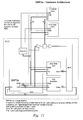
- each processor comprises a Core, an MMU (Memory Management Unit), an IVC (Interrupt Vector Controller) and a SIF Slave Module, see figures 53 and 54 and 71 .
- the Core communicates with memory external to the processor via the Memory Management Unit
- the Memory Management Unit can communicate with external memory including Flash memory, RAM and one or more registers.
- the memory management unit typically has address and read-write lines and data lines. These signals are typically uni-directional when on-chip.
- the data lines are typically bi-directional when off-chip.
- the SIF Slave Module in the preferred embodiment is connected via each processor to each respective processor's Memory Management Unit, such that the SIF Slave module is able to control the memory control and address signals, thereby enabling it to read and write data from/to the processor's memory. This is used identically for xSIF and iSIF accesses.
- a number of further (control) lines are provided to enable interaction of the processor Core with the SIF Slave module.
- an xSIF interface a number of lines are provided between the SIF Slave module and the SIF Pod, including the SIF_CLK, SIF_MOSI, SIF_MISO and SIF_LOADB lines referred to above.
- a further input to the SIF Slave ASIC is the chip select line SIF_CS.
- the 16-wire interface from the SIF Pod contains 4 lines that may be used as separate SIF_CS lines to up to 4 SIF Slave ASICs.
- the apparatus further comprises at least one control line, and wherein operation of the interface controller is dependent upon a signal applied to the control line.
- the apparatus processes instructions passed via the internal (iSIF) and external interfaces (xSIF) in alternate fashion.
- the apparatus further comprises means for arbitrating the processing of instructions passed via the internal (iSIF) and external (xSIF) interfaces.
- iSIF internal (iSIF) and external (xSIF) interfaces.
- the instructions passed via the external (xSIF) interface take precedence over instructions passed via the internal (iSIF) interface.
- a data processing apparatus including a processor, and an interface capable of communicating with the processor, each processor having associated memory, registers and debug instructions, and wherein the interface provides access to the memory, registers and debug instructions of the or each processor.
- the (SIF) interface comprises at least one (SIF) master module and at least one (SIF) slave module.
- the SIF slave enables a SIF master to access one or more on- or off-chip processors.
- the SIF master is provided on-chip. More preferably, the SIF master communicates via an internal (iSIF) interface.
- iSIF internal
- the SIF master further comprises an off-chip device. More preferably, the off-chip device communicates via an external (xSIF) interface.
- xSIF external
- access via the SIF interface to the processors is non-invasive.
- the processor's functionality and timing remain unchanged by a SIF access.
- the data processing apparatus is in the form of a single semiconductor device or chip containing one interface and one or more processors.
- the term semiconductor device is intended to connote an ASIC or FPGA implemented in silicon or germanium or gallium-arsenide or some other semiconductor material.
- the semiconductor device is also referred to as a chip.
- interface communications are initiated by a master and responded to by a slave.
- the interface master may be implemented on or off chip.
- the master can read and write to the memory and registers of one or more processors.
- the master can also issue debug instructions to one or more processors.
- communications between the master and slave(s) may be from within the semiconductor device (internal) or from outside the semiconductor device (external).
- the internal interface is a parallel interface.
- the external interface is a serial interface.
- the internal interface master is implemented in hardware in the form of another processor or dedicated state machine.
- the internal master can read and write registers and memory of one or more processors. This can be used to download software after system reset, to capture and store processor state before turning processor power off, to restore processor state after turning processor power back on, to read memory mapped IO registers in real-time in a non-invasive manner.
- the IO register could be an ADC (analogue to digital converter).
- the internal master can also issue debug instructions to one or more processors. This can be used to start, stop, single step, set breakpoint, run to breakpoint and reset one or more processors.
- the slave is adapted to support both an internal and external interface.
- the internal interface is to an internal master.
- the external interface is to an external master. More preferably, the internal interface is parallel and the external interface is serial.
- Network SIF debug and multiprocessor support / Networked SIF / iSIF + xSIF
- a network which comprises a computer, one or more pods, one or more chips, each containing one or more processors and communications protocols, wherein the communications protocols allow the computer to interact with any of the processors.
- a network according to claim 1, wherein the communications between computer and processors may be non-invasive to the processor's functional behaviour, so does not affect that processor's functionality or timing.
- the original SIF interface (XAP patent, 1994) provided non-invasive debug to a single processor in a single chip.
- the new SIF interface (xSIF & iSIF) provides non-invasive debug to many chips each potentially containing many processors.
- the SIF debug interface locally via USB interface or remotely via ethernet interface.
- One of the functions of the chips is to communicate with each other (e.g via a radio link or power-line communications).
- This functional interface may still many bugs.
- the debug computer may be able to monitor the packets of information travelling between the chips. It may also be able to download and debug software to all the processors in all the chips. This allows it to single-step or set break-points for all or any of the processors, and creates a very complete debug environment that allows the computer to find and fix software bugs within a complex network system.
- the network debug system may also be used to find hardware bugs in the chip designs before they have been made into silicon.
- a hardware emulator based on an FPGA Field Programmable Gate Array
- the debug computer may be connected to the emulators via the SIF network in the same way as it would be to the final chips.
- This debug environment can be used to find hardware and software bugs. When a hardware bug is found, it may be fixed and the FPGA re-progcammed. When a software bug is found, it can be fixed from the debug computer and downloaded to the relevant processor in the relevant chip.
- the Network SIF Debug system may include many features to support the above functionality. In addition, these features may operate within the constraints of modem high-speed, low-power, software-configurable devices. These are described in the following sections.
- the iSIF and or xSIF may contain one or more willing hardware slaves; they may be easy to turn off (low power), and or easy to read & write (program download, data acquisition).
- Off-chip devices are served by xSIF which is a serial interface of 4 (or optionally 5) pins.
- On-chip devices are served by iSIF which is a parallel interface. In both cases this may allow the Master to: read and write to memory-mapped devices (RAM, ROM, Flash, IO Register); read and write to Processor Registers; and issue debug commands (e.g. Start, Stop, Single-Step, Run-to-Breakpoint, Reset).
- SIF networks consisting of SIF Computer + SIF Pods + SIF Slaves
- xSIF for the following purposes: downloading software to target memory in selected processor in selected chip; executing debug instruction in selected processor in selected chip; and reading back data from memory of selected processor in selected chip (static data or continuous data for real-time data-acquisition).
- iSIF makes these features available to an on-chip SIF Master. This is becoming more common as chip sizes increase and complete networks may exist in a single chip.
- the SIF Master might be another processor or might be a small hardware state machine. Either way, the on-chip Master may access the SIF instructions via the iSIF. Because it is all on-chip it is acceptable to have a parallel interface with many signals. By using a parallel interface, iSIF may enable much faster execution of SIF instructions than xSIF.
- iSIF is likely to be used for control of software download from non-volatile memory (e.g Flash or EEPROM) to RAM at bootup time; data-acquisition from a Slave processor memory to the Master without affecting the Slave's timing or functionality; and full processor debug to all the Slave processors - e.g if the Master processor already has its own debug interface (e.g JTAG) it can enable full debug of all the processors from the original debug interface, via iSIF to all the SIF Slaves. This avoids the need to add any extra external pins to the chip. It also means that it may be possible to create a single debug tool on the computer that can be aware of all the processors on the chip, thus creating a fully integrated debug environment
- the SIF module has been designed to have a ping-pong system that alternates between xSIF and iSIF requests.
- the SIF module may process an iSIF request (if there is one) before processing the next xSIF request.
- the SIF module may process an xSIF request (if there is one) before processing the next iSIF request. This means that the xSIF and iSIF channels will generally appear to be open to the SIF Masters.
- XAP3 In a further aspect there is provided the ability to simultaneously monitor and debug a plurality of SIF Slaves. Multiprocessor debugging is provided. Multi-processor support in xIDE (a particular Integrated Development Environment) may be used. Data packets flowing between SIF Slaves (e.g radio or power-line communications devices) may be monitored.
- SIF Slaves e.g radio or power-line communications devices
- a device interface apparatus comprising a plurality of interfaces each comprising respective means for writing data to and/or reading data from a respective device, and control means for controlling operation of the plurality of interfaces.
- Each device may be a slave and/or may comprise a processor.
- the apparatus further comprises a plurality of control means each adapted to control a respective plurality of interfaces.
- each interface further comprises means for instructing operation of a respective device.
- the apparatus further comprises a computer adapted to communicate with, and preferably control, the or each control means.
- the SIF computer is adapted to receive data from and/or send data to one or more devices via the or each control means.
- the or each computer is adapted to communicate with a respective plurality of control means using a packet based protocol, for instance TCP/IP or ethernet.
- a packet based protocol for instance TCP/IP or ethernet.
- the apparatus comprises means for detecting errors in packets sent between the or each computer and at least one of the control means.
- the or each interface comprises a register, preferably a shift register, and preferably the or each interface comprises a SIF slave module.
- the control means comprises a SIF Pod and/or a control computer.
- the processor is a XAP3 processor.
- the processor and the interface are on the same circuit board and/or form part of an ASIC or FPGA.
- the interface and/or the control means and/or the computer comprises means for debugging the or each device and/or comprises means for capturing data from the or each device and/or comprises means for analysing data from the or each device.
- Figure 1 shows a plurality of networked SIF slaves linked to a SIF Pod/Master.
- SIF slaves Networking of SIF slaves allows a single computer to access many SIF Slaves simultaneously which enables, for instance, de-bugging and/or data acquisition, on a wide scale.
- Multiprocessor de-bug may be operated and/or developed in the xIDE environment
- Debugging of multiprocessors in a single chip may also be provided.
- This aspect may have particular application to meshing of networked radio devices, particularly when used for communication of non-voice data which a plurality of separate radio devices are able to identify and communicate with each other.
- meshing may be used to control lights in a warehouse.
- a particular light may be controllable using a radio transmitter.
- the radio signal from the transmitter may be passed via a plurality of radio devices (for instance located on other lights) located between the light and the transmitter.
- the radio devices work out, usually upon power up, how to communicate with each other and pass messages on to the intended recipient device.
- Each radio device has a unique number.
- Each device may be used as stand-alone (often battery powered) device, passing data to and via other devices via radio links.
- Each device may be connected via Ethernet in order to enable multi-processor debugging.
- the devices may communicate by radio links between themselves but may also each have an Ethernet connection to the SIF Computer to enable debugging and other data transfer.
- the SIF may, for instance, be used for debugging and also for production test and data acquisition.
- the SIF enables the reading of and writing to various specified addresses or registers inside a chip in real time without changing its functionality or timing. It is non-invasive. In general the timing of the chip is not changed.
- a chip may be connected up in its real mode to, for instance, a sensor, to a radio, to a USB link, to a RS232 link, or to a CAN link and at the same time may have another wire (e.g SIF) going in which may not be part of the application, allowing monitoring of operation without changing operation or timing.
- a sensor for instance, a sensor, to a radio, to a USB link, to a RS232 link, or to a CAN link and at the same time may have another wire (e.g SIF) going in which may not be part of the application, allowing monitoring of operation without changing operation or timing.
- XAP4 In a further aspect there is provided the ability to simultaneously monitor and debug a plurality of processors and associated memories. Multiprocessor debugging is provided. Multi-processor support in xIDE (a particular Integrated Development Environment) may be used. Data packets flowing between SIF Slaves (e.g. radio or power-line communications devices) may be monitored.
- SIF Slaves e.g. radio or power-line communications devices
- the xSIF master accessing multiple ASICs each having one xSIF interface. Furthermore, the xSIF master may also access multiple processors within each ASIC. Alternatively there can be a single iSIF master accessing multiple processors via an iSIF within the same ASIC. In this way, the xSIF and iSIF masters may access each processor's associated memory, registers and debug instructions.
- the processor is a XAP4 processor.
- a chip may be connected up in its real mode to, for instance, a sensor, to a radio, to a USB link, to a RS232 link, to a LPT link or to a CAN link and at the same time may have another wire (e.g SIF) going in which may not be part of the application, allowing monitoring of operation without changing operation or timing.
- a sensor for instance, a sensor, to a radio, to a USB link, to a RS232 link, to a LPT link or to a CAN link and at the same time may have another wire (e.g SIF) going in which may not be part of the application, allowing monitoring of operation without changing operation or timing.
- SIF another wire
- SIF Slaves may contain a simple parity-checking scheme. This may have separate parity bits for: PARITY_AC for Address + Control fields (1 parity bit for both fields together), PARITY_D for Data field, and PARITY_S for Status field.
- the SIF configurations for XAP3 and XAP4 can mean that if the SIF_MOSI or SIF_MISO pins are stuck high or low, parity errors may be reported in PARITY_AC and PARITY_S respectively. This is because in both cases the parity bits may be set for odd parity over an even number of bits. This configuration can generally expose both stuck high & low faults. If even parity is used or there are an odd number of bits being parity-protected, then some stuck at faults may not be exposed.
- the Parity bits may expose any odd number of bit errors in each of the 3 protected fields. They do not generally expose an even number of errors. In practice this means that they can only be relied upon for up to 1 bit error in each field.
- an apparatus comprising an interface adapted to communicate with a processor, and a control means adapted to communicate with, and/or control operation of, the interface, the apparatus further comprising monitoring means for monitoring communication of data, preferably between the control means and the interface.
- the monitoring means is adapted to perform an error checking procedure to determine whether there has been an error in communicating data between the interface and the control means.
- the data comprises at least one parity bit and the monitoring means is adapted to carry out a parity checking procedure with respect to the or each parity bit
- the data comprises a plurality of fields, and at least one parity bit is included in or associated with at least one of the plurality of fields.
- the plurality of fields comprise at least one of an address field, a data field, a control field, and a status field.
- control field contains a parity bit, preferably a PARITY_AC bit.
- parity bit is odd parity (including the parity bit itself) for the combined address and control fields.
- whole field is an even number of bits.
- the status field contains a parity bit, preferably a PARITY_D bit
- parity bit is odd parity (odd number of 1s) for the combined data field and the parity bit itself
- the status field contains a further parity bit, preferably a PARITY_S bit.
- parity bit is odd parity (odd number of 1 s) for the status field (including the further parity bit itself).
- the apparatus is adapted to carry out a further operation on the data, or on a field included in the data, in dependence on the outcome of the parity checking procedure.
- the monitoring means is adapted to monitor communication of data between the interface and the processor, and preferably the monitoring means is adapted to perform an error checking procedure to determine whether there has been an error in communicating data between the interface and the processor.
- the monitoring means is adapted to monitor data received by the interface from the control means and/or is adapted to monitor data received by the control means from the interface.
- the interface comprises a SIF
- the processor comprises an 8-bit, 16-bit, 32-bit, or 64-bit processor.
- the processor comprises a XAP1, XAP2, or XAP3 processor.
- the control means comprises a SIF master and/or a control computer.
- the apparatus comprises means for debugging, or for acquiring data from, the interface and/or the processor.
- the processor may form part of an ASIC or FPGA and preferably the interface also forms part of the ASIC or FPGA.
- the processor and the interface are on the same circuit board.
- Parity bit checking in and/or out of the SIF, may be provided. Parity bit checking is provided for both xSIF and iSIF accesses.
- the interface comprises a SIF
- the processor comprises an 8-bit, 16-bit, 32-bit, or 64-bit processor.
- the processor comprises a XAP1, XAP2, XAP3, XAP4 or XAP5 processor.
- the control means comprises a SIF master and/or a control computer.
- the apparatus comprises means for debugging, or for acquiring data from, the interface and/or the processor.
- the processor may form part of an ASIC or FPGA and preferably the interface also forms part of the ASIC or FPGA.
- the processor and the interface are on the same circuit board.
- xIDE support for multi-processors / SIF enables processor functions to be split across devices
- the SIF Computer needs to run debug software that gives it control of substantially every processor on substantially every chip in the network.
- This may be done by the xIDE software running on the SIF Computer. It may download software, read and write memory and run debug functions for substantially every processor in the debug network by using the SIF debug network. In addition it may support multiple processors sharing the same memory, which is a complicated debug problem.
- a processor apparatus comprising a first processor, a second processor and interface means adapted to enable communication between the first processor and the second processor.
- the first processor and the second processor are adapted to co-operate together via the interface means, and preferably the first processor is adapted to perform first aspects of a process and the second processor is adapted to perform second aspects of a process.
- the second processor is programmable, so that the second aspects of the process may be varied
- the second aspects comprise aspects relating to a user interface, and/or pricing aspects, and/or language aspects (i.e functions that may need to be modified during product lifetime).
- the first aspects comprise critical functionality of the process.
- the first aspects comprise aspects of the process which require regulatory approval.
- the first aspects comprise functionality that is likely to remain fixed throughout the product lifetime.
- the first processor is adapted to carry out the first aspects of the process in dependence upon instructions that may be stored in ROM (because they are likely to remain fixed).
- the second processor is adapted to carry out the second aspects in dependence upon instructions stored in RAM, or Flash memory, or in some other rewritable memory (because they are unlikely to remain fixed).
- the interface further comprises means for instructing operation of the first processor and/or the second processor.
- the first processor is part of an ASIC or FPGA.
- the interface comprises a SIF interface.
- SIF enables silicon partitioning.
- a SIF may be used for monitoring and data logging and analysis in, for instance, production, monitoring, and analysis systems.
- a SIF is used in a gas meter system.
- An ASIC is used for front end applications.
- the ASIC in effect implements all of the critical functionality of the system but different products are made for the German, French, British and American markets due to the different regulatory requirements.
- a separate ASIC is not produced for each market. Instead, an external microprocessor is provided which talks to the ASIC over the SIF.
- the microprocessor can access the ASIC in a way which is not invasive.
- the design is partitioned so that the critical science functionality cannot be tampered with, as it is locked in the ASIC. Whereas the external microprocessor may vary from one market to another.
- Bluetooth functionality which have obtained regulatory approval
- features which do not require regulatory approval are separated between features of Bluetooth functionality which have obtained regulatory approval, and features which do not require regulatory approval.
- a chip is provided which includes features of Bluetooth functionality which require or have obtained regulatory approval.
- a separate software development environment is provided which can be used (for instance by a customer) to customise features of the product, for instance, buttons and LED's. It is ensured that in customising features, the Bluetooth functionality cannot be broken, or changed in such a way that it would be needed to reapply for radio approvals.
- the first processor is part of an ASIC or FPGA.
- the interface comprises a SIF interface. This may be an xSIF or iSIF interface.
- the second processor is an xSIF master and on a separate chip from the first processor.
- the two processors are both on the same chip.
- the second processor is an iSIF master.
- Previous SIFs only supported 2 fields; address and data.
- the computer software drivers constrained these field sizes to be 1 to 32 bits.
- the address field was used for address and control (read/write, prog/data side, word size etc) functions. This meant that in practice the address and data buses could not be a full 32 bits.
- the data field was used for data and status (e.g time-stamp) functions. This meant that in practice the data bus could not be a full 32 bits.
- the SIFs described herein may use 4 fields: address, control, data, and status. All 4 fields may be parameterised to be any size from 1 to 32 bits. This means that it is able to support 32-bit processors with full 32-bit address bus & 32-bit data bus. Aspects of this new SIF system (from SIF Computer, through the SIF Pods and onto SIF Slaves containing several processors) reflect these 4 fields. e.g the xSIF API in the SIF Computer (as used by xIDE and Matlab tools) reflects these 4 SIF fields. The field sizes are configured differently for XAP3, XAP4 or other processors.
- the SIF Computer is generally a Master, it generally initiates SIF instructions.
- the processors in the chip (SIF Slave) are generally slaves and generally respond to the request initiated by the Master.
- the SIF instructions may be executed in a non-invasive manner. Even with network debug, they do not generally affect the timing or functionality of the selected processor. This is essential for any system that needs to maintain a frequency plan. This is a requirement for many applications, for example the DSP function for a radio system.
- the 4 SIF fields help to identify a particular processor on the selected chip.
- the xSIF API helps to identify which chip the SIF Master wants to communicate with. This all helps full non-invasive network debug to be supported.
- the SIF Master can specify exactly what it wants the SIF Slave to do in every SIF Instruction. It doesn't need to assume any state, such as 'SIF Instructions to this chip are currently going to Processor 3'. This kind of assumption is necessary for many short-word protocols. This makes it very difficult for the SIF Master because it is frequently impossible for it to make any assumptions about processor state. Consequently it has to send multiple instructions every time (& even they are not atomic - might be split by a request from a different Master) which makes the whole network much slower & sometimes cannot work at all.
- a processor interface apparatus comprising a register adapted to be connected to a processor and to read data from and/or write data to the processor.
- the register comprises a plurality of fields, preferably at least three fields, each field comprising at least one bit
- the plurality of fields comprises at least one of, and preferably all of an address field, a control field, a data field, and a status field.
- the address field comprises an address in the processor from which data is to be read or to which data is to be written, and/or the address field comprises information which identifies an operation, for instance a debug operation, to be performed by the processor.
- the data field comprises data to be written to, or data which has been read from, the processors.
- the apparatus is adapted to write the data to the address specified in the address field.
- the apparatus is adapted to read the data from the address specified in the address field.
- control field comprises data relating to control of the processor and/or the register and/or a further component of the processor interface apparatus, and/or relating to control of communication between the register and the processor and/or a further component of the processor interface apparatus.
- control field comprises data relating to at least one of: error checking, parity checking, processor identification, type of operation to be carried out (for instance read or write), mode information (for instance debug mode, SIF mode), and data-size information.
- the status field comprises data relating to the status of at least one of the processor, the register, and a further component of the processor interface apparatus, and/or relating to communication between at least one of the processor, the register, and a further component of the processor interface apparatus.
- the status field comprises data relating to the status of a process carried out by at least one of the processor, the register, and a further component of the processor interface apparatus.
- the status field comprises at least one of an error code a parity code and a timestamp.
- the contents of the status field are independent of the address.
- An error code may comprise a SIF error code or a processor error code.
- An error code may be included in the status field.
- the register comprises 88 bits.
- the address field comprises 32 bits.
- the control field comprises 8 bits.
- the data field comprises 32 bits.
- the status field comprises 16 bits. Such a configuration of the fields is typically used in the XAP3 processor.
- the register may comprise 52 bits.
- the address field comprises 16 bits.
- the control field comprises 8 bits.
- the data field comprises 16 bits.
- the status field comprises 12 bits.
- the further component of the apparatus comprises at least one of a SIF Pod or SIF Master, communicating with a SIF Computer running SIF Driver software.
- the register comprises a shift register, and preferably the register forms part of a SIF Slave module.
- the SIF Slave module is adapted to communicate with a SIF Pod or SIF Master.
- the processor is a XAP3 processor.
- processor and the register are on the same circuit board and/or form part of an ASIC.
- Each of the four fields may be up to 32 bits long.
- the four fields may be address, control, data and status fields.
- the address and data fields for certain embodiments must be 32 bits in length.
- Transfer of data to and from the address, control, data and status fields in the preferred embodiment is illustrated diagrammatically in figure 19 .
- API Application Programming Interface
- the API enables a programmer to program an application which talk to SIF Slaves via SIF Pods.
- the application may, for instance, be written in xIDE or SIF Toolkit or Matlab.
- the API may be an xSIF API or a SIF API.
- the SIF API has the concept of two fields (address, data), each of which can be up to 32 bits, the lengths being parameterisable. This can be used, for instance, with XAP1 and XAP2 processors.
- XAP1 may have a 36 bit shift register.
- XAP2 may have a 64 bit shift register.
- the XAP3 processor requires an 88 bit shift register. This cannot be supported by the SIF API, which can only support shift registers up to 64 bits in length.
- the xSIF API has the concept of four fields (address, control, data, status), each of which can be up to 32 bits, the lengths being parameterisable.
- the xSIF API is capable of supporting the 88-bit shift register used by the XAP3 processor.
- SIF and SIF APIs are portable across several different computer platforms and programming languages.
- two fields are provided (address & data), each of 64 bits. This can also support the 88-bit shift register used by the XAP3 processor.
- address and data fields have to be 32 bits, and address is interpreted the same way in the SIF as in the processor.
- the SIF may have, for instance, four or five pins.
- the XAP3 SIF allows access to up to 8 processors on the same chip.
- control field there is a write bit which identifies whether a SIF instruction is a read or a write.
- a debug bit which identifies whether a SIF instruction is a normal instruction or a debug instruction.
- control field there are two size bits which say whether a read or write is to use 8, 16 or 32-bit data.
- XAP4 The sizes of each the respective four SIF fields must be the same for the xSIF and iSIF interfaces.
- the register comprises 52 bits.
- the address field comprises 16 bits.
- the control field comprises 8 bits.
- the data field comprises 16 bits.
- the status field comprises 12 bits.
- the SIF address field is the same width as the processor address bus and the SIF data field is the same width as the processor data bus.
- the SIF control and status fields are independent of any processor bus widths.
- the SIF control field is identical in all preferred embodiments of the invention. Thus, a single SIF device may be used to debug a variety of processors on the same chip.
- the register comprises a shift register, and preferably the register forms part of a SIF Slave module.
- the SIF Slave module is adapted to communicate with a SIF Pod or SIF Master.
- the processor is a XAP4 processor.
- Transfer of data to and from the address, control, data and status fields in the preferred embodiment is illustrated diagrammatically in figure 50 .
- the XAP4 processor requires a 52 bit shift register.
- the SIF API can support a shift register having two fields, each up to 32 bit in length (i.e. a total of 64 bits in length), However, the XAP4 processor requires a shift register having four fields.
- the SIF API has the concept of four fields (address, control, data, status), each of which can be up to 32 bits, the lengths being parameterisable.
- the xSIF API is thus capable of supporting the 52-bit shift register used by the XAP4 processor.
- two fields are provided (address & data), each of 64 bits. This can also support the 52-bit shift register used by the XAP4 processor.
- the XAP4 SIF allows access to up to 8 processors on the same chip.
- control field there is a write bit which identifies whether a SIF instruction is a read or a write.
- Single Chip Single Chip (single SIF) support for multiple processors.
- apparatus comprising an interface adapted to be connected to a plurality of processors, and adapted to communicate with each processor individually.
- the interface is also adapted to communicate with the plurality of processors together.
- the interface is responsive to a processor identifier.
- each of the processors is responsive to at least one respective processor identifier.
- the apparatus is arranged to establish communication between the interface and one or more of the processors in dependence on a processor identifier.
- the processor identifier is included in a portion of data, and the interface is adapted to process the portion of data, and in particular to send the portion of data to, or receive the portion of data from, a particular processor or processors, in dependence upon the processor identifier.
- the interface is adapted to read data from or write data to a particular processor or processors in dependence upon the device identifier.
- the apparatus is adapted to read the portion of data into and/or out of a register, preferably a shift register.
- the interface is adapted to send a reset instruction to a particular processor or processors identified by the processor identifier.
- the reset instruction may be one of a plurality of reset instructions.
- One of the reset instructions may be such as to reset the particular processor or processors to a normal mode of operation, preferably running in the normal mode of operation.
- Another one of the reset instructions may be such as to reset the particular processor or processors to a debug mode of operation, preferably stopped in the debug mode of operation.
- a processor identifier may identify a plurality of the processors, preferably all of the processors.
- the interface comprises a SIF or SIF module, preferably each processor comprises an 8 bit, 16 bit, 32 bit, or 64 bit processor.
- each processor comprises a XAP1, XAP2, or XAP3 processor.
- each interface forms part of an interface apparatus which preferably includes means for debugging, or for acquiring data from the interface and/or the or each processor.
- the processors may form part of an ASIC or FPGA and preferably the interface also forms part of the ASIC or FPGA.
- the processors and the interface are on the same circuit board.
- particular bits may be allocated in every SIF instruction which identify a processor, if any, with which the instruction is concerned.
- SIF single-in-SIF
- processors per SIF multiple processors per chip
- the chip may comprise an ASIC or FPGA.
- Each SIF instruction may be directed to any one or ones of the multiple processors.
- command mode enables information concerning the SIF to be obtained.
- Direct de-bug SIF instructions in normal mode also enable information concerning the SIF to be obtained.
- Processor debug SIF instructions may specify one or more of the plurality of processors to which those instructions are to be sent
- a particular chip may be connected to a computer.
- the computer using a SIF master installed on or connected to the computer, may go into command mode.
- the SIF master may talk to the SIF to find out how many processors there are on the chip and what types they are. It may read various addresses and subsequently (when having left normal mode) communicate with any of the processors. It may also find out from the SIP what the lengths are of the various SIF fields. It may also obtain an ASIC identifier, if one exists which would tell it more about the chip it is connected to. Subsequently the computer may put the system into normal mode and could then, for instance, debug processor 0 while leaving processor 1 and 2 running. Processor 0 and 1 may be, say, XAP3 whereas processor 2 may be, say, XAP2. Individual processors can be reset or the whole chip can be reset. Single step or run to break point operation may be set on one processor whilst another is set to run normally. All of these functions are provided in the preferred embodiment without adding any extra pins.
- a processor interface apparatus comprising an interface for writing data to and/or reading data from a plurality of processors, and control means for controlling operation of the interface.
- Using a single interface to access several processors uses fewer chip pins than having a separate interface for each processor. For example, a single SIF interface with 4 chip pins may be used to access 8 on-chip processors.
- the interface further comprises means for instructing operation of each of the plurality of processors.
- the plurality of processors form part of a single chip.
- the plurality of processors form part of an ASIC or FPGA.
- the interface comprises a SIF Slave module.
- control means comprises a SIF Pod and/or a control computer.
- each of the plurality of processors comprises one of a XAP1 processor, a XAP2 processor and a XAP3 processor.
- XAP4 Multiple processors per SIF - multi processor support, direct SIF instruction (talking direct to the SIF). Multiprocessor support is provided for xSIF and iSIF accesses.
- the interface comprises a SIF or SIF module, preferably each processor comprises an 8 bit, 16 bit, 32 bit, or 64 bit processor.
- each processor comprises a XAP1, XAP2, XAP3, XAP4 or XAP5 processor.
- each interface forms part of an interface apparatus which preferably includes means for debugging, or for acquiring data from, the interface and/or the or each processor.
- the processors may form part of an ASIC or FPGA and preferably the interface also forms part of the ASIC or FPGA.
- the processors and the interface are on the same circuit board.
- the SIF master may talk to the SIF to find out how many processors there are on the chip and what types they are. It may read various addresses and subsequently (when having left normal mode) communicate with any of the processors. It may also find out from the SIF what the lengths are of the various SIF fields. It may also obtain an ASIC identifier, if one exists which would tell it more about the chip it is connected to. Subsequently the computer may put the system into normal mode and could then, for instance, debug processor 0 while leaving processor 1 and 2 running. Processor 0 and 1 may be, say, XAP4 whereas processor 2 may be, say, XAP2. Individual processors can be reset or the whole chip can be reset. Single step or run to break point operation may be set on one processor whilst another is set to run normally. All of these functions are provided in the preferred embodiment without adding any extra pins.
- each of the plurality of processors comprises one of a XAP1 processor, a XAP2 processor and a XAP4 processor.
- the XAP3 and XAP4 hardware may have 2 asynchronous reset inputs (resetb_xap, resetb_sif).
- the XAP3 and XAP4 hardware may have 2 asynchronous reset inputs (resetb_xap, resetb_sif).
- XAP4 hardware may also have 4 synchronous reset outputs. These may be controlled by direct SIF instructions. If connected up correctly they can individually cause resets to occur in separate regions of the chip: reset a selected XAP (or other) processor; reset the SIF (or other) chip debug section; reset User Gates (on-chip). The hardware designer can decide what circuitry should be reset by this signal; and reset off-chip devices. This signal is an external pin if used.
- the central SIF Computer can accurately send specific reset signals to the desired region of every processor in substantially every chip on the debug network. This may be necessary because it is often necessary to put substantially all the SIF Slave devices into a known state and then start them together or in a known sequence in order to debug a complex network system.
- the 'Reset SIF' instruction may be a direct SIF instruction that can be executed at any time. It does not generally require the SIF to be put into debug mode. Generally, there is only one SIF module per chip, so it is not necessary to specify a processor.
- the instruction may be accompanied by a required data value, to reduce the risk of a SIF reset being caused by accident
- the 'Reset XAP' instruction may also be a direct SIF instruction. It may require the selected XAP processor to already be in Debug mode. This is to reduce the risk of a XAP reset being caused by accident
- a processor interface apparatus comprising a processor, an interface and means for a resetting operation of at least part of the apparatus.
- the resetting means is adapted to reset at least part of the processor, at least part of the interface, at least part of at least one further processor, and/or at least part of an associated device.
- Each of these reset operations can be selected individually or together as a simultaneous group.
- the resetting means is adapted to reset operation of the at least part of the apparatus, preferably the processor or the at least one further processor, independent of the state of operation of the processor or of the at least one further processor.
- the resetting means is adapted to reset operation of the at least part of the apparatus, preferably the processor or the at least one further processor, only if the processor or the at least one further processor is in a specified mode, preferably in a debug mode.
- the interface further comprises means for instructing operation of the processor.
- the interface comprises a SIF interface comprising at least one of a SIF Slave module and a SIF Pod.
- the processor comprises at least one of a XAP1, XAP2, or XAP3 processor.
- the processor forms part of an ASIC or FPGA.
- SIF instructions are either normal SIF instructions or debug SIF instructions.
- Debug SIF instructions may be direct debug SIF instructions which are executed in the SIF and do not access any processor, or may be processor debug SIF instructions which refer to a selected processor.
- the various reset instructions coming from the SIF may be direct SIF instructions.
- Resets may be to everything, or to a chip, or to specific processors, or to the SIF.
- XAP3 Reset instructions from the SIF give precise control of which bits are reset.
- a processor interface apparatus comprising a processor, an interface and means for a resetting operation of at least part of the apparatus.
- the SIF instruction set is identical for xSIF and iSIF accesses. As such, the SIF reset instructions are identically available to xSIF and iSIF.
- the interface comprises a SIF interface comprising at least one of a SIF Slave module and a SIF Pod.
- the processor comprises at least one of a XAP1, XAP2, XAP3, XAP4 or XAP5 processor.
- the processor forms part of an ASIC or FPGA.
- Normal SIF instructions are shown first in the table, followed by direct debug instructions, followed by other debug instructions.
- SIF instructions are either normal SIF instructions or debug SIF instructions.
- Debug SIF instructions may be direct debug SIF instructions which are executed in the SIF and do not access any processor, or may be processor debug SIF instructions which refer to a selected processor.
- Direct SIF instructions to read preferably to read four counters / SIF status counters and Direct SIF instructions to read them
- a processor interface apparatus comprising a processor and an interface, the interface comprising means for reading data from and/or writing data to the processor, and the apparatus further comprising means for monitoring operation of the interface and/or operation of the processor and/or communication between the processor and the interface.
- the interface further comprises means for instructing operation of the processor.
- the monitoring means is adapted to monitor at least one of: the number and/or type and/or timing of data read or write operations between the interface and the processor, the number and/or type and/or timing of errors occurring in the interface, the processor or in communication between the processor and the interface; the number and/or type and/or timing of reset operations and/or cancellation operations occurring in the interface, the processor, or in communication between the interface and the processor, the quantity of data read, write or transferred; and the timing of data readings by the processor.
- the interface comprises a SIF interface comprising at least one of a SIF Slave module and a SIF Pod.
- the processor comprises at least one of a XAP1, XAP2, or XAP3 processor.
- the processor forms part of an ASIC or FPGA.
- At least one self monitoring SIF counter may monitor the number of reads, writes, errors and number of cancellations, preferably using direct SIF instructions.
- the SIF itself has at least one counter, and preferably four counters, which monitor SIF activity.
- the SIF counters monitor at least one of the number of SIF reads since reset, the number of writes, the number of errors which have occurred and the numbers of times SIF operation has been cancelled.
- This aspect is particularly useful in connection with the running of, say, a data acquisition system, particularly an overnight data acquisition system, gathering large quantities of data. It enables a user to identify if there had been any problems during the data acquisition process.
- the interface comprises a SIF interface comprising at least one of a SIF Slave module and a SIF Pod.
- the processor comprises at least one of a XAP1, XAP2, XAP3, XAP4 or XAP5 processor.
- the processor forms part of an ASIC or FPGA.
- SIF Slave When a SIF Master issues a SIF instruction to a SIF Slave, it may be that the SIF Slave is running code in normal mode that does not contain any sif or sleepsif instructions. This would mean that the SIF Slave could not generaly respond to the SIF Instruction and may cause the xSIP or iSIF bus (the one used for the request) to hang. This may crash a part of the debug network. So it is necessary to detect and fix such a problem when it occurs. This is particularly important in a large network that may contain hundreds of SIF Slave devices. The SIF Computer may be able to detect any part of the network that has crashed and be able to repair it automatically.
- the SIF Master may have a Cancel method to fix it
- iSIF For iSIF this may be achieved with the isif_cancel input signal.
- the iSIF Master pulls this signal high, it may cancel the pending SIF instruction which the iSIF Master can see because the isif_done output signal will go high.
- SIF SIF this may be done by one of several methods including: pulling SIF_CS low, SIF_CS is an optional pin, so this will not always be possible; and toggling SIF_CLK 32 times and sampling SIF_MOSI for, for example, the last 8 clocks. This may indicate what type of Cancel to occur. Such a Cancel can specify whether to cancel an xSIF instruction or an iSIF instruction or both.
- iSIF cannot cancel an xSEF instruction, but xSIF can cancel an iSIF instruction.
- xSIF has priority.
- an external debug system xSIF Master
- xSIF Master can generally guarantee to put the chip into a known state, despite what lockup condition it has got into. It would not be good to let the iSIF Master cancel an xSIF request. If the iSIF Master software had bugs it could crash the system and prevent the external debug system from recovering the situation and putting the chip back into a known state. That is why generally the iSIF Master cannot cancel an xSIF instruction.
- a processor interface apparatus comprising an interface and a processor, the interface being adapted to communicate with the processor when the processor is in a communication mode.
- the processor is adapted to enter the communication mode in response to a signal from the interface.
- the processor is adapted to exit the communication mode in response to an indication that a communication process has been completed successfully.
- the interface is adapted to communicate with the processor only when the processor is in a communication mode and the interface is in a communication mode.
- the interface is adapted to enter the communication mode in response to a signal from the processor that the processor is in the communication mode.
- the interface and the processor are adapted to communicate using a handshake procedure.
- means for making the processor and/or the interface exit the communication mode is included in a control means.
- the processor is adapted to exit the communication mode in response to a signal, preferably a signal from the interface, regardless of whether the communication process has been completed successfully or not
- the processor is adapted to exit the communication mode in response to the interface stopping requesting communication.
- the interface is adapted to stop requesting communication in response to a cancel signal from a or the control means.
- the interface comprises a SIF interface comprising at least one of a SIP Slave module and a SIF Pod.
- the processor comprises a XAP3 processor.
- the processor forms part of an ASIC or FPGA.
- the control means comprises a SIF pod and/or a SIF computer.
- At least one SIF cancel method is provided.
- the master/pod detects SIF lockup with a time out.
- the slave may tell the master that it made an illegal request
- a master may queue up a request and a slave may be waiting to process the request but may never get an answer and thus may stay stuck low.
- a SIF may not be usable thereafter, and may produce an error message such as SIF error' (even though the error would not have been with the SIF).
- SIF_LOADB may get stuck low, in known handshake procedures, occur when an invalid request is made, for instance when: an undefined SIF instruction is given; if it is requested to write to a register which is read-only; a request is made which requires being in debug mode but the SIF is not in debug mode; or a request is made whilst a processor is running which requires the processor to be stopped or to execute a processor-sif or processor-sleepsif instruction.
- the master pulls the slave chip select pin (SIF_CS) low, causing the slave to no longer be selected and clearing any pending SIF cycles which are stuck.
- SIF_CS slave chip select pin
- the slave automatically stops pulling the relevant pin low, regardless of actions that have taken place, after a certain number of clock cycles, for instance 32 cycles on SIF_CLK.
- the SIF is cleared simultaneously for all the slaves.
- the first method typically requires that each slave be cleared in tum. However, usually no more than one slave should be selected at any one time, so no more than one slave should be stuck at any one time in any event
- the second method typically clears all slaves simultaneously.
- a pod makes a request that can't be completed by the slave because it has not received the relevant processor-sif or processor-sleepsif instructions it leaves SIF_LOADB stuck low. That tells the pod that it has requested something that it shouldn't have done.
- the SIF Computer detects a timeout and then issues a SIF CANCEL procedure which will clear the stuck SIF and allow SIF_LOADB to go high again.
- XAP4 The means for cancelling a SIF access is available to both the xSIF and iSIF interfaces.
- an iSIF master If an iSIF master has to wait too long for an iSIF access it performs a time-out and cancels the iSIF access with the isif_cancel signal.
- an xSEF master If an xSEF master has to wait to long for an xSIF access it performs a time-out and cancels the xSEF access using one of the xSIF cancel methods.
- the interface comprises a SIF interface comprising at least one of a SIF Slave module and a SIF Pod.
- the processor comprises a XAP4 processor.
- the processor forms part of an ASIC or FPGA.
- the control means comprises a SIF pod and/or a SIF computer.
- the slave automatically stops pulling the relevant pin low, regardless of actions that have taken place, after a certain number of clock cycles, for instance 32 cycles on SIF_CLK.
- the SIF is cleared simultaneously for all the slaves.
- This method can cannel an xSIF, an iSIF or both accesses. These different types of cancels are distinguished by the SIF slave sampling SIF_MOSI for the last 8 cycles of SIF_CLK.
- a common SIF instruction is for the SIF Master to read a memory location of a specified address on a specified processor on a specified SIF Slave device.
- the response data values arrive in a different order from that in which the requests were issued. It is very useful to know whether the SIF instruction executed cleanly or with an error. If there was an error it is useful to know what type of error it was. For all responses, it is useful to know the exact time at which the SIF Slave formed its response (Data and Status fields).
- the Status field may be used for error reporting and for capturing the value of any user-selected hardware register in the ASIC at the time the SIF instruction is completed (for SIF read or write). It is often useful to make this register a hardware timestamp, i.e. a counter that is clocked at some known rate. This means that when the SIF Master receives the response from the SIF instruction, that it will generally know the time at which the SIF instruction was completed in the SIF Slave.
- the SIF Computer may reconstruct a series of data samples with the correct time interval between them. It also may expose whether there are any missing data samples (which is important when trying to characterise an analogue cell such as an ADC).
- Having the Status field for the timestamp means that the Data field is left free for a full 32-bit data bus.
- a processor interface apparatus comprising a register, preferably a shift register, adapted to be connected to a processor and to read data from and/or write data to the processor.
- the register is adapted to include time stamp data.
- the register comprises a plurality of fields, preferably at least three fields, and more preferably four fields, each field comprising at least one bit, and preferably the time stamp data is included in at least one of the fields.
- the time stamp data corresponds to a portion of data, preferably to a portion of data written to or read from the register.
- the time stamp data indicates when the portion of data was written to or read from the register and/or written to or read from the processor.
- the portion of data is data from a device, preferably a sensing device, associated with the processor, and the timestamp indicates when the portion of data was recorded by the device.
- the plurality of fields comprises at least one of, and preferably all of: an address field, a control field, a data field, and a status field.
- time stamp data is included in the status field
- the corresponding portion of data may be included in the data field.
- the register comprises 88 bits.
- the address field comprises 32 bits.
- the control field comprises 8 bits.
- the data field comprises 32 bits.
- the status field comprises 16 bits.
- the further component of the apparatus comprises at least one of a SIF Pod or SIF Master together with a SIF Computer running SIF Driver software.
- the register comprises a shift register, and preferably the register forms part of a SIF Slave module.
- the SIF Slave module is adapted to communicate with a SIF Pod, or SIF Master.
- the processor is a XAP3 processor.
- a SIF time stamp is provided.
- the status field is 16 bits in the preferred embodiment, and the top two bits used are as parity bits (PARITY_S, PARITY_D).
- STAT is a time stamp, this is discussed in more detail below.
- processors according to the invention may be used, for instance, in software debug, production tests or data acquisition.
- the SIF is used to acquire data from a processor relating to each of those activities.
- the master continuously requests data from the slave.
- the slave attaches a time stamp to each piece of data that it sends to the master.
- the master can analyse the timestamps to see if it has missed any piece of data, or whether it has received two or more pieces of data from the same sampling period at the master, or whether it has received two or more pieces of data with the same timestamp.
- the timestamp is synchronised with a data sampling rate at the master.
- a pod controls transfer of data, and the pod does not have to respond to transactions initiated by the slave.
- the same SIF interface is used for debug and for data acquisition.
- the data-transfers are always initiated by the SIF Pod and Computer, never by the SIF Slave. This means that in the preferred embodiment the SIF Slave never 'throws' data, even during data-acquisition.
- the SIF Slave in the preferred embodiment always responds to requests from the SIF Pod, whether it is being used for control or data-acquisition. This makes it much easier to create a deterministic data-transfer system. The problem is that during data-acquisition, some data samples may be acquired more than once, and other samples may be missed. The SIF timestamp is a system solution to this problem.
- ADC analog to digital converter
- the signal being sampled is over-sampled to ensure that no samples are missed.
- characterising an ADC it is important not to miss any samples. It is also important to know whether two copies of the same data have been obtained.
- a typical software loop for an ASIC processor comprises: obtaining new data; then executing the software; then issuing a processor-sleepsif instruction to enable the external SIF Pod to obtain data from the ASIC.
- the processor-sleepsifwindow the SIF can get many reads of the same data The SIF does not know at that time whether it is in cycle n or cycle n +1.
- a hardware counter which is incremented at some known rate normally correlated to the data acquisition rate within the chip (for instance about 24kHz).
- the status field is arranged to give extra data which is independent of the address. In the case where a lot of reads are being carried out, the data is from the address requested.
- the status field is independent of the address requested and can be used for any ASIC register or memory at any address.
- the status field is used to provide a time stamp.
- the time stamp is an indication of sample number. Accordingly, it is possible to determine whether duplicate copies of the same data have been obtained, or whether samples have been missed.
- the data obtained may be post-processed, for instance in Matlab. Duplicate copies of data may then be discarded. Accordingly one, and only one, copy of the relevant data is obtained by the post processing.
- This feature is particularly useful when using PCs in a data acquisition process as PCs can occasionally miss data acquisition for periods of time, typically 2 to 3 millisecond in length.
- the use of a time stamp enables identification of periods where data is missing.
- shift register bit definitions for the preferred embodiment are provided.
- shift register bits are divided between address, control, data and status fields in the preferred embodiment, and that there are 32 address bits, 8 control bits, 32 data bits, and 16 status bits.
- Transfer of data to and from the address, control, data and status fields in the preferred embodiment is illustrated diagrammatically in figure 19 .
- the 8 bits of the control field are made up of three processor bits (control bits 2:0), one debug bit (control bit 3), two size bits (control bits 5:4), one parity bit (control bit 6), and one write bit (control bit 7).
- shift register bits 40 to 71 which make up the 32 bit data field
- the data field may be used for 8, 16, or 32 bit read and write operations.
- the status field can be used for a variety of purposes. It can be seen that two of the status bits are used as parity bits, six of the status bits are used as error bits, and eight of the status bits are used for other status purposes, which may include being used as a time stamp.
- bits in particular status bits, may be used for other purposes or in different combinations. For instance, thirteen of the sixteen status bits could be used as a time stamp, or for other status purposes.
- status and control fields are broken down into individual bits, each bit having its own function either alone or in combination with other bits.
- Time stamp data may be included in the data field, typically when there is no status field.
- the value of the status field is preferably independent of the address field.
- the time stamp frequency may be chosen to suit a particular purpose, and may be chosen on command of a user.
- the time stamp is dependent on operation of the SIF and/or of the processor. It may be synchronised with a data acquisition update rate or a software loop rate.
- the time stamp comprises a count of a number of clock pulses.
- Data written to the status field may comprise a software register written to by the processor, as well as or instead of time stamp data.
- the register comprises 52 bits.
- the address field comprises 16 bits.
- the control field comprises 8 bits.
- the data field comprises 16 bits.
- the status field comprises 12 bits.
- the register comprises a shift register, and preferably the register forms part of a SIF Slave module.
- the SIF Slave module is adapted to communicate with a SIF Pod, or SIF Master.
- the processor is a XAP4 processor.
- the status field is 12 bits in the preferred embodiment, and that the top two bits used are as parity bits (PARITY_S, PARITY_D).
- STAT is a time stamp, discussed in more detail below.
- 16 bit data can be read, together with a time stamp associated with that 16 bit data.
- shift register bit definitions for the preferred embodiment are provided.
- shift register bits are divided between address, control, data and status fields in the preferred embodiment, and that there are 16 address bits, 8 control bits, 16 data bits, and 12 status bits.
- Transfer of data to and from the address, control, data and status fields in the preferred embodiment is illustrated diagrammatically in figure 50 .
- shift register bits 24 to 39 (which make up the 32 bit data field) that in the preferred embodiment the data field may be used for 8, 16, or 32 bit read and write operations.
- bits in particular status bits, may be used for other purposes or in different combinations. For instance, nine of the twelve status bits could be used as a time stamp, or for other status purposes.
- the SIF Computer may be connected to many SIF Slave chips via the SIF debug network. It is important that the SIF Computer is able to recognise what kind of device each SIF Slave is, for the network may be connected to many different types of SIF Slave device. Different SIF Slave devices may have different SIF shift register lengths and be connected to different numbers of internal processors, each of which needs to be identified.
- SIF command mode may allow a SIF Master to automatically interrogate a SIF Slave device via xSIF.
- a SIF Master may automatically interrogate a SIF Slave device via xSIF.
- iSIF it is not necessary for iSIF as the on-chip processor types will be known at chip design time.
- SIP command mode may be a standard protocol which uses substantially all the xSIF pins except SIF LOADB. This means that the SIF commands do not generally cause a SIF instruction to be executed, which is a desirable feature. Generally, identifying what kind of device the SIF Slave is should not affect its behaviour or operation.
- SIF command mode reveals to the SIF Master: the size of the 4 SIF fields (address, control, data, status); what kind of processor (if any) there is at each of the 8 on-chip processor locations from 0 to 7; the ASIC identifier.
- the SIF Master may perform this automatically and there is not generally any need for manual configuration by the user.
- the SIF command mode enables plug and play. Different SEFs may be of different length: the SIF command mode may be used mainly for query functions. Use of the SIF command mode enables query functions without the need to add extra pins, without affecting normal operation and without having any ambiguity of command
- an interface apparatus comprising an interface, adapted to communicate with a device, for instance a processor, and a control means adapted to communicate with and/or control the interface, the interface being adapted to send data concerning itself to the control means and the control means being adapted to configure itself, or the interface, dependent upon the data.
- the interface is adapted to send the data concerning itself to the control means when in a specified mode, preferably a Command mode.
- a command set for use in the Command mode, the command set comprising a plurality of commands.
- the interface is one of a plurality of interfaces, and preferably each interface is adapted to recognise a respective sub-set of the command set or all of the command set. Preferably all of the interfaces recognise a common sub-set of the command set.
- interface interrogation functionality is provided without the need to add additional hardware, for instance additional pins, and without affecting existing modes of operation.
- Existing modes of operation may comprise, for instance, Normal SIF instructions. Debug SIF instructions, and SIF Cancel operations.
- the data comprises at least one of a specific processor or chip identifier, or a generic interface identifier identifying the type of interface, preferably the type of SIF interface, or data representing at least one individual characteristic of at least one component of the interface, preferably a SIF interface.
- the at least one individual characteristic may comprise a field length, for instance an address, control, data, or status field length.
- the at least one individual characteristic may comprise information concerning the bits within a field, in particular within the control and/or status fields.
- the interface may be one of a plurality of interfaces.
- each interface comprises a respective shift register.
- each shift register comprises a plurality of fields.
- the interface is adapted to send data concerning itself in response to a request signal from the control means.
- the request signal comprises a specified sequence of signals.
- the apparatus is arranged so that the request signal may be sent from the control means to the interface over a channel which is normally used to send other signals between the control means and the interface, and the interface is adapted to recognise and respond to the request signal when sent over the channel.
- the request signal comprises a specified sequence of 8, 16, 32, 64, 128, or 256 bits or other data units.
- the interface is adapted to enter a command mode in response to the request signal.
- the interface is adapted to exit the command mode in response to a further request signal, which may be the same as or different to the request signal.
- the interface comprises a SIF.
- the control means comprises a SIF Pod and/or a control computer.
- the processor comprises an 8bit, 16 bit, 32 bit or 64 bit processor.
- the processor may be a XAP 1 processor, a XAP2 processor or a XAP3 processor.
- the processor may form part of an ASIC or FPGA and preferably the interface also forms part of the ASIC or FPGA.
- the processor and the interface are on the same circuit board.
- the request signal represents a command in Command mode.
- SIF normally operates in Normal mode.
- a Command mode is provided for interrogation purposes, in particular to ascertain characteristics of a particular SIF.
- all SIFs recognise certain common commands in Command mode, and all SIFs enter the Command mode in the same way.
- particular SIFs may not be adapted to recognise all commands in Command mode.
- Different SIFs may have shift registers of different lengths.
- all SIFs recognise request commands requesting a chip identifier, or SIF type, or number or type of processors associated with the SIF, or SIF field length, or information concerning bits within a SIF field.
- Command mode if the SIF does not recognise a command it generates a response of 0xFF.
- the range of responses to any valid command in Command mode is 0x00 to 0xFE.
- the Command mode enables a SIF plug and play functionality.
- SIF characteristics may vary, and in particular characteristics of the SIF shift register or SIF shift register fields, in particular SIF shift register length or SIF shift register field length, may vary for different SIFs and/or for different processors with which a SIF may be associated.
- the SIF shift register length is typically 32 bits, 64 bits, and 88 bits respectively.
- a command mode is provided When the SIF is in the command mode, the master can interrogate the SIF, typically using query function. When in the command mode, in the preferred embodiment, the SIF does not access the associated processor; the SIF is returned to normal mode when access to the associated processor by the SIF is required.
- the command mode is entered in response to a series of 256 clocks/bits representing successive 'Hex 33333...' signals on the SIF_MOSI line.
- all commands are 8 bits in and 8 bits out.
- the master can ask various questions, for instance 'what is the address field length?' 'what is the control field length?' 'What is the data field length?' 'How many processors do you have?' 'what types of processors are they at the various places?'.
- an instruction set which the SIF can recognise in command mode.
- command mode can be entered without having to pull SIF_LOADB low.
- command mode is entered, the device is interrogated, the apparatus is tailored to the device if necessary, and then normal mode is entered.
- XAP4 SIF command mode is in generally used for xSIF accesses.
- the interface is adapted to send the data concerning itself to the control means when in a specified mode, preferably a Command mode.
- a command set for use in the Command mode the command set comprising a plurality of commands.
- the interface is one of a plurality of interfaces, and preferably each interface is adapted to recognise a respective sub-set of the command set or all of the command set Preferably all of the interfaces recognise a common sub-set of the command set
- the interface comprises a SIF.
- the control means comprises a SIF Pod and/or a control computer.
- the processor comprises an 8bit, 16 bit, 32 bit or 64 bit processor.
- the processor may be a XAP1 processor, a XAP2 processor a XAP3 processor or a XAP4 processor.
- the processor may form part of an ASIC or FPGA and preferably the interface also forms part of the ASIC or FPGA.
- the processor and the interface are on the same circuit board.
- the request signal represents a command in Command mode.
- the SIF shift register length is typically 32 bits, 64 bits, 88 bits and 52 bits respectively.
- a command mode is provided.
- the master can interrogate the SIF, typically using query functions.
- the SIF does not access the associated processor; the SIF is returned to normal mode when access to the associated processor by the SIF is required.
- processors per chip and or multiple chips.
- modem chips contain more than one processor. It is common to have a control processor and a data processor (e.g. a DSP). Sometimes there will be more than 2 processors on a given chip. These processors may each have their own memories or may share memory. Either way, it is important that the network debug system is still able to access all the processors and their associated memories in every chip on the network. Furthermore these features should be provided in a non-invasive manner and with fast access times.
- Some debug systems e.g. JTAG
- JTAG Some debug systems (e.g. JTAG) only allow a 1-dimensional daisy chain access to all the on-chip devices. This can result in very long shift registers and slow access times if there are many on-chip processors.
- SIF may provide a random access, 2-dimensional access to substantially every processor and substantially every memory on the chip. This means that the network debug is provided in a fast manner via xSIF and iSIF to substantially all the on-chip devices. This is vastly superior to a 1-dimensional solution.
- the default SIF module in XAP3 and XAP4 systems may support up to 8 on-chip processors in this 2-dimensional parallel manner.
- SIF Master may issue a direct SIF instruction which will cause substantially every processor in a single chip to stop when any of those processors hit a breakpoint. This is a very valuable feature when debugging multiple-processor systems. There is also the more conventional simple direct SIF instruction which causes a single processor to stop when it hits a breakpoint. Both features are needed in a network debug system.
- apparatus comprising an interface adapted to be connected to a plurality of processors, and adapted to communicate with each processor individually.
- the interface is also adapted to communicate with the plurality of processors together.
- the interface is responsive to a processor identifier.
- each of the processors is responsive to at least one respective processor identifier.
- the apparatus is arranged to establish communication between the interface and one or more of the processors in dependence on a processor identifier.
- the processor identifier is included in a portion of data, and the interface is adapted to process the portion of data, and in particular to send the portion of data to, or receive the portion of data from, a particular processor or processors, in dependence upon the processor identifier.
- the interface is adapted to read data from or write data to a particular processor or processors in dependence upon the device identifier.
- the apparatus is adapted to read the portion of data into and/or out of a register, preferably a shift register.
- the interface is adapted to send a reset instruction to a particular processor or processors identified by the processor identifier.
- the reset instruction may be one of a plurality of reset instructions.
- One of the reset instructions may be such as to reset the particular processor or processors to a normal mode of operation, preferably running in the normal mode of operation.
- Another one of the reset instructions may be such as to reset the particular processor or processors to a debug mode of operation, preferably stopped in the debug mode of operation.
- a processor identifier may identify a plurality of the processors, preferably all of the processors.
- the interface comprises a SIF or SIF module, preferably each processor comprises an 8 bit, 16 bit, 32 bit, or 64 bit processor.
- each processor comprises a XAP1, XAP2, or XAP3 processor.
- each interface forms part of an interface apparatus which preferably includes means for debugging, or for acquiring data from, the interface and/or the or each processor.
- the processors may form part of an ASIC or FPGA and preferably the interface also forms part of the ASIC or FPGA.
- the processors and the interface are on the same circuit board.
- particular bits may be allocated in every SIF instruction which identify a processor, if any, with which the instruction is concerned.
- SIF single-in-SIF
- processors per SIF multiple processors per chip
- the chip may comprise an ASIC or FPGA.
- Each SIF instruction may be directed to any one or ones of the multiple processors.
- command mode enables information concerning the SIF to be obtained.
- Direct de-bug SIF instructions in normal mode also enable information concerning the SIF to be obtained.
- Processor debug SIF instructions may specify one or more of the plurality of processors to which those instructions are to be sent
- a particular chip may be connected to a computer.
- the computer using a SIF master installed on or connected to the computer, may go into command mode.
- the SIF master may talk to the SIF to find out how many processors there are on the chip and what types they are. It may read various addresses and subsequently (when having left normal mode) communicate with any of the processors. It may also find out from the SIF what the lengths are of the various SIF fields. It may also obtain an ASIC identifier, if one exists which would tell it more about the chip it is connected to. Subsequently the computer may put the system into normal mode and could then, for instance, debug processor 0 while leaving processor 1 and 2 running. Processor 0 and 1 may be, say, XAP3 whereas processor 2 may be, say, XAP2. Individual processors can be reset or the whole chip can be reset. Single step or run to break point operation may be set on one processor whilst another is set to run normally. All of these functions are provided in the preferred embodiment without adding any extra pins.
- a processor interface apparatus comprising an interface for writing data to and/or reading data from a plurality of processors, and control means for controlling operation of the interface.
- Using a single interface to access several processors uses fewer chip pins than having a separate interface for each processor. For example, a single SIF interface with 4 chip pins may be used to access 8 on-chip processors.
- the interface further comprises means for instructing operation of each of the plurality of processors.
- the plurality of processors form part of a single chip.
- the plurality of processors form part of an ASIC or FPGA.
- the interface comprises a SIF Slave module.
- control means comprises a SIF Pod and/or a control computer.
- each of the plurality of processors comprises one of a XAP1 processor, a XAP2 processor and a XAP3 processor.
- XAP4 Multiple processors per SIF - multi processor support, direct SIF instruction (talking direct to the SIF). Multiprocessor support is provided for xSIF and iSIF accesses.
- the interface comprises a SIF or SIF module, preferably each processor comprises an 8 bit, 16 bit, 32 bit, or 64 bit processor.
- each processor comprises a XAP1, XAP2, XAP3, XAP4 or XAP5 processor.
- each interface forms part of an interface apparatus which preferably includes means for debugging, or for acquiring data from, the interface and/or the or each processor.
- the processors may form part of an ASIC or FPGA and preferably the interface also forms part of the ASIC or FPGA.
- the processors and the interface are on the same circuit board.
- the SIF master may talk to the SIF to find out how many processors there are on the chip and what types they are. It may read various addresses and subsequently (when having left normal mode) communicate with any of the processors. It may also find out from the SIF what the lengths are of the various SIF fields. It may also obtain an ASIC identifier, if one exists which would tell it more about the chip it is connected to. Subsequently the computer may put the system into normal mode and could then, for instance, debug processor 0 while leaving processor 1 and 2 running. Processor 0 and 1 may be, say, XAP4 whereas processor 2 may be, say, XAP2. Individual processors can be reset or the whole chip can be reset. Single step or run to break point operation may be set on one processor whilst another is set to run normally. All of these functions are provided in the preferred embodiment without adding any extra pins.
- each of the plurality of processors comprises one of a XAP1 processor, a XAP2 processor and a XAP4 processor.
- SIF Slave When a SIF Master is doing data acquisition from a SIF Slave, it may be possible for the SIF Slave to control the rate of data requests.
- the SIF Master may sit in a loop continually requesting SIF reads from the SIF Slave.
- the SIF Slave may only let the SIF read instruction complete when it is ready (by holding isif_done of SIF_LOADB low). This allows the SIF Slave to reduce noise and interference caused by xSIF transactions while it is making sensitive ADC readings from its analogue circuitry. This is valuable as it can increase the accuracy of the analogue readings.
- the SIF Slave can contain FIFO (First-In, First-Out) hardware for capturing the data samples.
- the FIFO can be hardware-coupled to the SIF, so that the SIF instruction is only completed when a new piece of data has arrived in the FIFO.
- isif_done for iSIF
- SIF_LOADB for xSIF
- This hardware method may leave the processor free to get on with other processing while the FIFO is waiting for the next data sample.
- XAP3 Synchronising a FIFO with SIF_LOADB for data acquisition, without extra pins.
- an interface apparatus comprising an interface and a processor, the processor comprising a register for temporary storage of data, and the interface being adapted to read data stored in the register.
- the apparatus further comprises means for sending a signal to the interface indicating that the register has been updated, the interface being adapted to read updated data stored in the register in response to the update signal.
- the apparatus further comprises control means adapted to communicate with the interface.
- the apparatus comprises means for sending to the control means data read from the register by the interface.
- control means is adapted to establish a communication session with the interface.
- sending means is adapted to send the data from the interface to the control means during a communication session.
- sending means is adapted to maintain a communication session between the control means and the interface pending updated data becoming available to be sent from the interface to the control means.
- the interface comprises an interface register arranged so that data read from the register is read to the interface register.
- the register comprises a FIFO (first in, first out).
- the interface comprises a SIF
- the processor comprises an 8 bit, 16 bit, 32 bit, or 64 bit processor.
- the processor comprises a XAP1, XAP2, or XAP3 processor.
- the control means comprises a SIF master and/or a control computer.
- the apparatus comprises means for debugging, or for acquiring data from, the interface and/or the processor.
- the processor may form part of an ASIC or FPGA and preferably the interface also forms part of the ASIC or FPGA.
- the processor and the interface are on the same circuit board.
- the processor executes a processor-sif instruction or a processor-sleepsif instruction.
- An associated SIF may read data from the FIFO.
- a handshake procedure may be provided between the SIF and a master.
- the master may make a request and the SIF_LOADB may stay low until the new data obtained from the FIFO.
- the SIF would then release the new data to the master.
- XAP4 xSIF accesses may synchronise a FIFO with SIF_LOADB for data acquisition, without extra pins.
- iSIF accesses may synchronise a FIFO with isif_load for data acquisition.
- the interface comprises a SIF
- the processor comprises an 8 bit, 16 bit, 32 bit, or 64 bit processor.
- the processor comprises a XAP1, XAP2, XAP3, XAP4 or XAP5 processor.
- the control means comprises a SIF master and/or a control computer.
- the apparatus comprises means for debugging, or for acquiring data from, the interface and/or the processor.
- the processor may form part of an ASIC or FPGA and preferably the interface also forms part of the ASIC or FPGA.
- the processor and the interface are on the same circuit board.
- a handshake procedure may be provided between the SIF and an xSIF master.
- the xSIF master may make a request and the SIF_LOADB may stay low until the new data is obtained from the FIFO. The SIF would then release the new data to the xSIF master.
- a handshake procedure may be provided between the SIF and an iSIF master.
- the iSIF master may make a request with isif_load and the isif_done signal may stay low until the new data is obtained from the FIFO.
- the SIF would then release the new data to the iSIF master.
- Modem communication protocols are based on packets of data. They have high bit-rate, but low packet-rate. i.e. the data packets are large. Wireline protocols such as Ethernet and USB both display this characteristic. The same also applies to wireless protocols such as WiFi (IEEE 802.11) and Bluetooth.
- the SIF should also be capable of high granularity data transactions.
- the xSIF API contains simple low granularity instructions such as: xsif_read (), xsif_write ().
- xSIF API also contains high granularity instructions that can achieve high data throughput, such as: xsif_read_array (), xsif_read_block (), xsif_write_block ().
- apparatus comprising a control means, preferably a SIF pod, adapted to be connected to a control computer, preferably a SIF computer, and to send data to and/or receive data from the control computer, and means for performing an error checking and correction procedure on the data.
- control computer preferably a SIF computer
- the error checking procedure is based upon checking CRC codes included in the data.
- the SIF pod is adapted to be connected to the control computer via an ethernet or USB or RS232 or LPT link.
- the SIF pod is adapted to be connected to the control computer via an Ethernet or USB or RS232 or LPT link.
- the software If the software is happy for xSIF or iSIF transactions to occur during the sleep period, it should use a sleepsif instruction. If it is not happy for xSIF or iSIF instructions to occur during the sleep period, it should use the sleepnop instruction.
- the normal sif and sleepsif instructions enable iSIF or xSIF instructions to be executed.
- the XAP can individually enable just iSIF or just xSIF instructions by using the instructions: isif, xsif, sleepisif, and sleepsif.
- XAP3 In a further aspect there is provided an instruction for a processor adapted to communicate via an interface, the instruction when processed by the processor causing communication from the interface to the processor and/or from the processor to the interface to be stopped or not allowed, preferably for a fixed period and/or until a further instruction is processed.
- an interface for communication with a processor the interface being responsive to an instruction from the processor to stop communication with the processor and/or to not allow communication with the processor and/or to not allow transmission of data from the interface to the processor, preferably for a fixed period and/or until receipt of a further instruction.
- a sleepsif instruction may allow external debugger access to processor registers and memory while the processor is in the low-power sleep state.
- a sleepnop instruction may prevent SIF accesses.
- Distinct sleepnop and sleepsif instructions may be provided. Control from the slave end is thus provided, enabling it to ensure that the SIF is quiet, for instance allowing the slave to take readings.
- the processor has two states: a "sleeping" state and an "awake” state.
- the sleeping state at least part of the operation of the processor may be suspended, for example by suspending the execution of any further instructions, which may reduce the power consumed by the processor.
- the processor In the awake state, the processor may be capable of a greater degree of operation than is possible in the sleeping state: for example the processor may execute instructions that are not available in the sleeping state.
- the greater degree of activity permitted in the awake state results in the processor consuming more power whilst in the awake state than whilst in the sleeping state.
- the sleeping state may comprise two sub-states: a sleepsif state and a sleepnop state.
- the processor In the sleepsif state the processor may be capable of performing functions related to debugging, and in particular a SIF Module may be fully operable.
- a SIF Module In the sleepsif state, other functionality of the processor may not operable and in particular the processor may not operable to execute instructions unrelated to debugging such as those of User Mode programs.
- the processor may not be operable to execute any instructions: more particularly, neither instructions related to debugging nor instructions unrelated to debugging may be executed in the sleepnop state.
- the SIF Module may be inoperable.
- the provision of the sleepnop state can further reduce the power consumption of the processor relative to that of the sleepsif state and the processor awake state. Additionally, by deactivating the SIF Module in the sleepnop state, electrical noise that may be produced by the SIF Module may be reduced, which may allow more accurate measurements to be made by an analogue to digital converter that is incorporated in an electrical circuit comprising the microprocessor.
- SIF Computer can execute SIF instructions even in this state to read and write memory.
- SIF Instructions are enabled even when there is no sif or sleepsif instruction in the processor code.
- SIF instructions may require a sif or sleepsif instruction to be executed.
- the XAP3 sif instruction has been defined to be all 1s (32-bit version) and all 0s (16-bit version). This means that the processor is likely to execute sif instructions (which is a useful state) even from uninitialised memory.
- the processor-sif (background debug interface) instruction may be all-1's in 32-bit form, and/or all-0's in 16-bit form. This allows, for example, external SIF control (from the SIF Pod) when the internal ASIC processor data bus is stuck at all-1s or all-0s.
- a processor adapted to execute a debug instruction automatically upon the occurrence of a fault.
- the fault is an unintended or unforeseen mode of operation of a computer program being executed by the processor.
- the debug instruction is encoded by a binary word corresponding to logic levels that are likely to be found on a bus of the processor following a fault
- the bus is a program memory data bus.
- the debug instruction is encoded by a binary word in which all bits are 1 or as a binary word in which all bits are 0.
- the processor is capable of executing one or more instructions encoded as a binary word having a first length and one or more instructions encoded as a binary word having a second length, wherein the first length is greater than the second length.
- the processor is adapted to execute a long debug instruction encoded as a word of the first length and a short debug instruction encoded as a word of the second length.
- the short debug instruction is encoded by a word equal to the one's complement of the least significant bits of the long debug instruction.
- operation of the SIF Slave module may be initiated when a dedicated processor-sif instruction is executed by the processor Core.
- the processor-sif instruction may be stored in program memory (typically on a flash memory device) and read into the Core via the Memory Management Unit.
- the Core when a processor-sif instruction is read by the Core, the Core completes execution of its current instruction and sends a signal to the SIF Slave module by setting the Core's "SIF" output signal to a defined logic-level.
- the execution of further instructions by the Core is suspended until a "CONTINUE" signal is received by the Core from the SIF Slave module (the Core "CONTINUE” input signal typically using the same logic level as the "CONTINUE” output from the SIF Slave module).
- the SIF Slave module and debugger can be permitted to have uninhibited access to registers in the Core and to the rest of the apparatus. This can also allow debug access via the SIF Slave module to be easily synchronised with software being executed on the processor.
- the SIF instruction is encoded as 0x00000000.
- the SIF instruction is encoded as 0xFFFFFF.
- the SIF instruction is denoted by an instruction in which all bits are zero and/or in which all bits are 1.
- a SIF instruction is read from program memory into the Core, all of the 32 lines of the program memory data bus are high or all of the 32 lines of the program memory data bus are low.
- Such an arrangement of logic levels on the program memory data bus is also likely to occur following a fault (such as may be caused by incorrect operation of a program being executed by the Core, for example) or when no software has yet been loaded.
- the processor can be caused automatically to execute a SIF instruction immediately following such a fault This can allow operation of the SIF module to be initiated in response to the fault thereby allowing software to be debugged.
- the processor in 16-bit instruction mode the SIF instruction is encoded as 0x0000 and in 32-bit mode as 0xFFFFFFFF.
- Performance of an operation may require a processor-sif instruction. In certain circumstances, errors may result in the data bus being stuck at all 1s or all 0s.
- SIF instructions are either normal SIF instructions or debug SIF instructions.
- Debug SIF instructions may be direct debug SIF instructions which are executed in the SIF and do not access any processor, or may be processor debug SIF instructions which refer to a selected processor.
- the first three instructions in table 50 are SIF normal instructions, for reading from and writing to memory.
- the size of the data field is specified.
- a processor-sif or a processor-sleepsif instruction is first required from the processor.
- Some debug instructions may be executed immediately and may not need to wait for a SIF cycle.
- instructions for, for instance, going into debug mode; coming out of debug mode; reading status; reading version number; and reading licence number may be carried out without being in debug mode.
- debug mode a wide range of actions may be performed, for instance Stop, Run, Single Step, Run to Break.
- a SIF operation comprises three stages:- shift in stage, handshake stage and shift out stage.
- the processor-sif (background debug interface) instruction may be all-1's in 32-bit form, and/or all-0's in 16-bit form. This allows, for example, external SIF control (from the SIF Pod) when the internal ASIC processor data bus is stuck at all-1s or all-0s. This may be exploited by xSIF and iSIF accesses.
- SIF instructions are either normal SIF instructions or debug SIF instructions.
- Debug SIF instructions may be direct debug SIF instructions which are executed in the SIF and do not access any processor, or may be processor debug SIF instructions which refer to a selected processor.
- the first two instructions in table 71 are SIF normal instructions, for reading from and writing to memory.
- the size of the data field is specified.
- a processor-sif or a processor-sleepsif instruction is first required from the processor.
- a SIF operation comprises three stages:- shift in stage, handshake stage and shift out stage.
- XAP3 In a further aspect there is provided a processor instruction set which is not regular, but which is tailored to compiler behaviour and/or calling convention.
- registers are not all treated symmetrically by instructions.
- the instructions may play to the coding conventions used by the compiler.
- instruction set support for the compiler's conventions for function entry and exit can achieve significant improvement in code density.
- certain registers are used for certain functions by the C compiler. For instance there may be certain things that may require to be done by register R5 which are not required to be done with register R6. Accordingly, there may be particular instructions for, say, R5 and not for R6.
- the first five function arguments are passed in registers R1 to R5 and subsequent function arguments are passed on the stack (ie in memory). Therefore, in the preferred embodiment there are also provided instructions which have preferential support for registers R1 to R5.
- Examples of instructions which have preferential support for R1 to R5 in the preferred embodiment include:- the 16 and 32 bit forms of movm and movm.x; the 16 and 32 bit forms of pop.ret; the 16 bit forms ofldm and stm.
- R14 is used as a link register. This contains the function return address.
- R15 is used as a stack pointer. This contains the base address of the stack.
- All addresses are stored in registers as 32 bit byte addresses.
- Some instructions may, in practice be used often and other instructions may be used less often.
- 16 bit codings are given to those instructions which are used often, and only 32 bit codings are given to those instructions which are used less often.
- each compound instruction being adapted to carry out a plurality of actions.
- Examples of such compound instructions in the preferred embodiment include: movm.*; ldm.*; stm.*; push; push.r; pop; pop.ret; blkst.r; blkst.8.r and blkcps.r (where * is a wildcard character).
- the processor comprises an 8 bit, 16 bit, 32 bit, or 64 bit processor.
- the processor comprises a XAP1, XAP2, or XAP3 processor.
- the processor may form part of an ASIC or FPGA and preferably the interface also forms part of the ASIC or FPGA.
- the processor and the interface are on the same circuit board or chip.
- a processor having a variety of instruction sizes determined on an instruction by instruction basis.
- an immediate value of 0 is interpreted to represent -1. This is possible in the case where a register (in the preferred embodiment R0) represents zero. Thus code density may be further improved.
- Efficient function entry and exit is essential for good code density.
- efficient function entry is provided by the push and push.r instructions.
- Efficient function entry and exit is essential for good code density.
- efficient function exit is provided by the pop and pop.ret instructions.
- registers are used for certain functions by the C compiler. For instance there may be certain things that may require to be done by register R2 which are not required to be done with register R3. Accordingly, there may be particular instructions for, say, R2 and not for R3.
- the first three function arguments are passed in registers R0 to R2 and subsequent function arguments are passed on the stack (ie in memory). Therefore, in the preferred embodiment there are also provided instructions which have preferential support for registers R0 to R2.
- Examples of instructions which have preferential support for R0 to R2 in the preferred embodiment include: pop; pop.ret; and push.
- Examples of such instructions which have preferential support for R0 in the preferred embodiment include: pop.ret
- R6 is used as a link register. This contains the function return address.
- R7 is used as a stack pointer. This contains the base address of the stack.
- All addresses are stored in registers as 16 bit byte addresses.
- the processor comprises an 8 bit, 16 bit, 32 bit, or 64 bit processor.
- the processor comprises a XAP1, XAP2, XAP3, XAP4 or XAP5 processor.
- the processor may form part of an ASIC or FPGA and preferably the interface also forms part of the ASIC or FPGA.
- the processor and the interface are on the same circuit board or chip.
- a 3 bit field identifies whether the instruction is 16 or 32 bit.
- 7 of the 3 bit values represent 16 bit instructions and the remaining 8 th value represents 32 bit instructions. This ratio may result in close to optimum code density for a 16 bit processor. This leads to 56k 16 bit instructions and 512M 32 bit instructions.
- Efficient function entry and exit is essential for good code density.
- efficient function entry is provided by the push instruction.
- a processor which is provided without a constant zero register. In this way, compiled code density may be improved.
- the instruction includes both a read and a write form, in which case the instruction either reads data from or writes data to a memory location specified in part by the register.
- the read instruction is in the form of a load instruction (ld.p) and the write instruction is in the form of a store instruction (st.p). In this way code density may be improved.
- both the offset and PC are interpreted as byte addresses.
- Examples of instructions which have preferential support for R1 to R5 in the preferred embodiment include:- the 16 and 32 bit forms of movm and movm.x; the 16 and 32 bit forms of pop; the 16 and 32 bit forms of pop.ret; the 16 bit forms of ldm and stm; the 16 bit forms of push and push.r.
- each compound instruction being adapted to carry out a plurality of actions.
- Examples of such compound instructions in the preferred embodiment include:- movm.*; ldm.*; stm.*; push; push.r; pop; and pop.ret (where * is a wildcard character).
- an instruction for a processor for writing each of a plurality of portions of data to a respective register.
- at least one of the portions of data comprises an immediate.
- the instruction comprises a plurality of arguments, each argument comprising a respective one of the portions of data or a respective address (preferably a register selector).
- each portion of data preferably there is associated with each portion of data a respective flag which indicates whether that portion of data should be interpreted as an address (for instance a register selector) or as an immediate.
- an immediate value of 0 is interpreted to represent -1. This is possible in the case where a register (in the preferred embodiment R0) represents zero. Thus code density may be further improved.
- the or each address comprises the address (preferably a register selector) where a respective portion of data is stored, and preferably the instruction, when performed, is such as to cause the portion of data stored at the or each address (preferably a register selector) to be written to a respective one of the registers.
- the or each address is a register address or identifier, such as a register selector.
- the instruction comprises a series of arguments and the instruction, when performed, is such as to cause each of the series of arguments, or a respective portion of data obtained by processing of each of the series of arguments, to be written, in order, to a respective one of a series of registers.
- the processor comprises an 8 bit, 16 bit, 32 bit, or 64 bit processor.
- the processor comprises a XAP1, XAP2, or XAP3 processor.
- the processor may form part of an ASIC or FPGA.
- the movm instruction can move up to five registers or small immediate values into R1-R5, thus replacing up to five mov instructions with a single movm instruction.
- the order of writing to registers for movm is from R1 to R5.
- the order of writing to registers for movm.x is from R5 to R1. .
- an instruction for a processor which moves each of a plurality of data elements into a respective one of a plurality of registers, the instruction comprising at least one identifier and a plurality of arguments, each argument being representative of a respective one of the plurality of data elements, the at least one identifier identifying, for each argument, the type of data of which that argument is representative.
- each argument when processed, is processed in dependence upon the type of data of which it is representative.
- the types of data comprise register data and immediates, and each argument comprises one of a register address and an immediate value.
- both movm source and pop.ret return value fields can be registers or immediates, encoded as a 5-bit field: one bit specifies register/immediate, the remaining four bits specifying either one of R0-R15, or an immediate value of-1, 1, ..., 15.
- memory is only accessed through a load, from memory to register, or a store, from register to memory, or multiples of such operations, or through push and pop instructions, which are other multi-cycle instructions associated with the stack or with the swap instruction.
- an instruction for instance push and push.r in the preferred embodiment which writes multiple registers to a stack, allocates space for local (automatic) variables, and updates a stack pointer register accordingly.
- the push instruction pushes all selected registers from R1 to R14 onto the stack. This saves many instructions at the beginning of a function for saving call-save registers on the stack. This reduces power consumption.
- the push.r instruction pushes registers from R6 upwards, and then copies any of registers R1-R5 to matching registers from R6 onwands. This saves many instructions at the beginning of a function for saving call-save registers on the stack and copying argument registers into the upper registers. This uses even fewer memory accesses than the push instruction, thereby further reducing power consumption.
- both the push and push.r instructions assume that R15 is the stack pointer.
- Efficient function entry and exit is essential for good code density.
- efficient function entry is provided by the push and push.r instructions.
- an instruction for a processor for instance a pop or pop.ret instruction in the preferred embodiment
- loads at least one register from memory via a stack pointer, removes zero or more words of automatic storage (for instance as allocated by an instruction such as a push or push.r instruction in the preferred embodiment), and updates the stack pointer.
- Examples of instructions which have preferential support for R1 to R5 in the preferred embodiment include:- the 16 and 32 bit forms of movm and movm.x; the 16 and 32 bit forms of pop; the 16 and 32 bit forms of pop.ret; the 16 bit forms ofldm and stm; the 16 bit forms of push and push.r.
- Examples of such instructions which have preferential support for R1 in the preferred embodiment include: the 16 and 32 bit forms of pop.ret.
- each compound instruction being adapted to carry out a plurality of actions.
- Examples of such compound instructions in the preferred embodiment include:- movm.*; ldm.*; stm.*; push; push.r; pop; and pop.ret (where * is a wildcard character).
- memory is only accessed through a load, from memory to register, or a store, from register to memory, or multiples of such operations, or through push and pop instructions, which are other multi-cycle instructions associated with the stack or with the swap instruction.
- the instruction takes an additional argument (preferably a register or small immediate) and stores that argument in a register (for instance in R1 in the preferred embodiment), and updates condition flags as if that value was compared with 0.
- the instruction for instance the pop.ret instruction in the preferred embodiment
- executes a return via another register for instance the Link Register in the preferred embodiment. This reduces the number of instructions, thus reducing memory size and power consumption.
- Efficient function entry and exit is essential for good code density.
- efficient function exit is provided by the pop and pop.ret instructions.
- both movm source and pop.ret return value fields can be registers or immediates, encoded as a 5-bit field: one bit specifies register/immediate, the remaining four bits specifying either one of R0-R15, or an immediate value of-1, 1, ..., 15.
- a processor adapted to process portions of data of variable length, the processor comprising means for determining the length of a portion of data and being adapted to process the portion of data in dependence upon that determination.
- registers of the processor are not all treated symmetrically by the processor instructions.
- the use of registers is tailored to the coding conventions used by the compiler. Certain registers are used for certain functions by the compiler.
- the design of the 16-bit instruction set has been further optimised to be even closer to the output of the compiler; for example, some 16-bit instructions allow access to R1-R4 and R6-R9, skipping R5 due to register usage behaviour of the compiler.
- the preferred embodiment has been designed for code-density.
- register R5 there are certain things that it may be desired to do with, say, register R5 which it is not desired to do with, say, register R6. Accordingly, in the preferred embodiment there are certain instructions for R5 and not for R6.
- processor instruction set which is not regular, but which is tailored to compiler behaviour and/or calling convention.
- registers are not all treated symmetrically by instructions.
- the instructions may play to the coding conventions used by the compiler.
- instruction set support for the compiler's conventions for function entry and exit can achieve significant improvement in code density.
- certain registers are used for certain functions by the C compiler. For instance there may be certain things that may require to be done by register R5 which are not required to be done with register R6. Accordingly, there may be particular instructions for, say, R5 and not for R6.
- the first five function arguments are passed in registers R1 to R5 and subsequent function arguments are passed on the stack (ie in memory). Therefore, in the preferred embodiment there are also provided instructions which have preferential support for registers R1 to R5.
- Examples of instructions which have preferential support for R1 to R5 in the preferred embodiment include: the 16 and 32 bit forms of movm and movm.x; the 16 and 32 bit forms of pop; the 16 and 32 bit forms of pop.ret; the 16 bit forms of ldm and stm; the 16 bit forms of push and push.r.
- Examples of such instructions which have preferential support for R1 in the preferred embodiment include: the 16 and 32 bit forms of pop.ret.
- R14 is used as a link register. This contains the function return address.
- R15 is used as a stack pointer. This contains the base address of the stack.
- All addresses are stored in registers as 32 bit byte addresses.
- Some instructions may, in practice be used often and other instructions may be used less often.
- 16 bit codings are given to those instructions which are used often, and only 32 bit codings are given to those instructions which are used less often.
- each compound instruction being adapted to carry out a plurality of actions.
- Examples of such compound instructions in the preferred embodiment include: movm.*; ldm.*; stm.*; push; push.r; pop; and pop.ret (where * is a wildcard character).
- the processor comprises an 8 bit, 16 bit, 32 bit, or 64 bit processor.
- the processor comprises a XAP1, XAP2, or XAP3 processor.
- the processor may form part of an ASIC or FPGA and preferably the interface also forms part of the ASIC or FPGA.
- the processor and the interface are on the same circuit board or chip.
- XAP3 These features are implemented in certain embodiments of the invention (such as XAP3), and not implemented in other embodiments (XAP4 or XAP5).
- each compound instruction being adapted to carry out a plurality of actions.
- Examples of such compound instructions in the preferred embodiment include: push; pop; and pop.ret.
- XAP4 In a further aspect there is provided an instruction (for instance push in the preferred embodiment) which writes multiple registers to a stack, allocates space for local (automatic) variables, and updates a stack pointer register accordingly.
- the push instruction pushes all selected registers from R3 to R6 onto the stack. This saves many instructions at the beginning of a function for saving call-save registers on the stack. This reduces power consumption.
- the push instruction assumes that R7 is the stack pointer.
- Efficient function entry and exit is essential for good code density.
- efficient function entry is provided by the push instruction.
- the processor comprises an 8 bit, 16 bit, 32 bit, or 64 bit processor.
- the processor comprises a
- XAP 1, XAP2, XAP3, XAP4 or XAP5 processor may form part of an ASIC or FPGA.
- Examples of instructions which have preferential support for R0 to R2 in the preferred embodiment include:- pop; pop.ret; and push.
- Examples of such instructions which have preferential support for R0 in the preferred embodiment include:- pop.ret
- Examples of such compound instructions in the preferred embodiment include:- push; pop; and pop.ret.
- the instruction takes an additional argument (preferably a register or small immediate) and stores that argument in a register (for instance in R0 in the preferred embodiment), and updates condition flags as if that value was compared with 0.
- the instruction for instance the pop.ret instruction in the preferred embodiment
- executes a return via another register for instance the Link Register R6 in the preferred embodiment. This reduces the number of instructions, thus reducing memory size and power consumption.
- the design of the 16-bit instruction set has been further optimised to be even closer to the output of the compiler; for example, some 16-bit instructions allow access to R0-R6 but not to R7 due to register usage behaviour of the compiler.
- register R3 there are certain things that it may be desired to do with, say, register R3 which it is not desired to do with, say, register R2. Accordingly, in the preferred embodiment there are certain instructions for R3 and not for R2.
- certain registers are used for certain functions by the C compiler. For instance there may be certain things that may require to be done by register R2 which are not required to be done with register R3. Accordingly, there may be particular instructions for, say, R2 and not for R3.
- the first three function arguments are passed in registers R0 to R2 and subsequent function arguments are passed on the stack (ie in memory). Therefore, in the preferred embodiment there are also provided instructions which have preferential support for registers R0 to R2.
- Examples of instructions which have preferential support for R0 to R2 in the preferred embodiment include:- pop; pop.ret; and push.
- Examples of such instructions which have preferential support for R0 in the preferred embodiment include:- pop.ret.
- R6 is used as a link register. This contains the function return address.
- R7 is used as a stack pointer. This contains the base address of the stack.
- All addresses are stored in registers as 16 bit byte addresses.
- each compound instruction being adapted to carry out a plurality of actions.
- Examples of such compound instructions in the preferred embodiment include: push; pop; and pop.ret.
- the processor comprises an 8 bit, 16 bit, 32 bit, or 64 bit processor.
- the processor comprises a XAP1, XAP2, XAP3, XAP4 or XAP5 processor.
- the processor may form part of an ASIC or FPGA and preferably the interface also forms part of the ASIC or FPGA.
- the processor and the interface are on the same circuit board or chip.
- a processor adapted to process portions of data of variable length, the processor comprising means for determining the length of a portion of data and being adapted to process the portion of data in dependence upon that determination.
- registers of the processor are not all treated symmetrically by the processor instructions.
- the use of registers is tailored to the coding conventions used by the compiler. Certain registers are used for certain functions by the compiler.
- the design of the 16-bit instruction set has been further optimised to be even closer to the output of the compiler; for example, some 16-bit instructions allow access to R0-R6 but not to R7 due to register usage behaviour of the compiler.
- the preferred embodiment has been designed for code-density.
- register R3 there are certain things that it may be desired to do with, say, register R3 which it is not desired to do with, say, register R2. Accordingly, in the preferred embodiment there are certain instructions for R3 and not for R2.
- Instructions may be provided in 32 bit or 16 bit forms.
- each instruction can be 16 bit or 32-bit, freely mixed on an instruction-by-instruction basis.
- 16-bit instruction decode may be done serially (16->32) as a decompression stage prior to full 32-bit decode.
- each 16-bit instruction may be mapped onto a corresponding 32-bit instruction.
- an instruction set having equivalent instructions in short and long forms.
- all instructions in the instruction set are available in long form and a sub-set of the instructions is available in short form.
- instructions which are used frequently and which can be coded in a short form are provided in a short form.
- a processor adapted to process portions of data of variable length, the processor comprising means for determining the length of a portion of data and being adapted to process the portion of data in dependence upon that determination.
- the determining means is adapted to determine the length of a portion of data in dependence upon a length identifier, the length identifier preferably being included in or associated with the portion of data.
- the processor is adapted to process a series of portions of data in turn, the determining means being adapted to determine the respective length of each portion of data in turn, and the processor being adapted to process each portion of data in dependence on the respective determined length.
- the or each portion of data comprises an instruction.
- the or each portion of data may comprise at least one operator and may also comprise at least one argument.
- an instruction set preferably for a processor as described herein, comprising an instruction provided in a first portion of data having a first length and an instruction provided in a second portion of data having a second length, the first length being greater than the second length.
- the first portion of data comprises an argument and the second portion of data comprises a further argument, the length of the argument of the first portion of data being longer than the argument of the second portion of data.
- the first portion of data comprises an operator and the second portion of data comprises the same operator.
- each of the first portion of data and the second portion of data comprises a respective length identifier identifying the length of that portion of data.
- the first portion of data has a length of 32 bits and the second portion has a length of 16 bits.
- an instruction set comprising a first sub-set of instructions which are provided in both a first form and a second form, and a second sub-set of instructions which are provided in a first form.
- each instruction in its first form comprises a portion of data of a first length
- each instruction in its second form comprises a portion of data of a second length, the first length being greater than the second length.
- each instruction comprises an operator and/or an argument
- an or each instruction is provided in the second form or not in dependence on the length of a respective operator and/or in dependence on the length of a respective argument and/or in dependence on the likelihood that the instruction will occur in use of the instruction set.
- each instruction in its first form is a 32 bit instruction and each instruction in its second form is a 16 bit instruction.
- the processor comprises an 8 bit, 16 bit, 32 bit, or 64 bit processor.
- the processor comprises a XAP1, XAP2, or XAP3 processor.
- the processor may form part of an ASIC or FPGA and preferably the interface also forms part of the ASIC or FPGA.
- the processor and the interface are on the same circuit board.
- both 16 bit instructions and 32 bit instructions there are provided both 16 bit instructions and 32 bit instructions. At least some instructions are provided in both 16 bit form and 32 bit form, depending on the length of the argument included with the instruction, such instructions generally providing identical functionality in both their 16 and 32 bit forms.
- processor memory includes both 32 bit instruction space and 16 bit instruction space.
- 32 bit instruction space typically far more 32 bit instruction space is provided than 16 bit instruction space. For instance there may by, say, 64,000 times more 32 bit instruction space than 16 bit instruction space.
- the processor is defined by a 32 bit instruction set and a subset of that which is used frequently is coded in 16 bits. In the preferred embodiment there are around 32,000 different 16 bit instructions and around 2,000,000,000 different 32 bit instructions.
- the 32 bit instruction space overlaps the 16 bit instruction space. Instructions may be identical in their 16 bit form and 32 bit forms but they may they have different (i.e. smaller in the case of the 16 bit form) argument ranges.
- the instruction set is arranged so that roughly 60 to 70% of operations carried out are from 16 bit instructions (with regard to this statement at least, an operation could be considered to be, say, adding 13 to register R5, whilst, say, adding 14 to register R5 would be considered to be a different operation).
- the compiler produces assembler code which does not indicate whether an instruction is 16 bit or 32 bit. For each piece of assembler code, the assembler then determines whether there is underlying 16 bit code, or only underlying 32 bit code, available.
- a 16-32 bit converter adapted to convert 16 bit instructions to 32 bit instructions prior to execution.
- instructions have a minimum size of either 16 bits or 32 bits in the preferred embodiment
- Preferably 16 bit instructions also have a 32 bit form.
- Code numbers may be allocated in a way that makes the decode easier.
- each primary op code can take a 25 bit argument. The 25 bit argument may be split into different fields.
- Op code 63 is an extended op code. All extended op code instructions have arguments which are less than 25 bits (arguments of 21 bits or less) in the preferred embodiment Preferably, some instructions are provided which have a separate prime opcode for each register (eg mov.p). This allows coding long immediates in single instructions.
- each instruction can be 16 bit or 32-bit, freely mixed on an instruction-by-instruction basis.
- 16 bit instructions require a single memory fetch.
- 32 bit instructions require a double memory fetch.
- Some instructions are only available in 16 bit form. Some instructions are only available in 32 bit form. Some instructions are available in 16 and 32 bit forms.
- Instruction decode is performed as soon as the full instruction is available. This will be after the first fetch for 16 bit instructions and after the second fetch for 32 bit instructions.
- a 3 bit field identifies whether the instruction is 16 or 32 bit.
- 7 of the 3 bit values represent 16 bit instructions and the remaining 8 th value represents 32 bit instructions. This ratio may result in close to optimum code density for a 16 bit processor. This leads to 56k 16 bit instructions and 512k 32 bit instructions.
- an instruction set having equivalent instructions in short and long forms.
- instructions which are used frequently and which can be coded in a short form are provided in a short form.
- the processor comprises an 8 bit, 16 bit, 32 bit, or 64 bit processor.
- the processor comprises a XAP1, XAP2, XAP3, XAP4 or XAP5 processor.
- the processor may form part of an ASIC or FPGA and preferably the interface also forms part of the ASIC or FPGA.
- the processor and the interface are on the same circuit board.
- both 16 bit instructions and 32 bit instructions there are provided both 16 bit instructions and 32 bit instructions. At least some instructions are provided in both 16 bit form and 32 bit form, depending on the length of the argument included with the instruction, such instructions generally providing identical functionality in both their 16 and 32 bit forms.
- processor memory includes both 32 bit instruction space and 16 bit instruction space.
- 32 bit instruction space typically far more 32 bit instruction space is provided than 16 bit instruction space. For instance there may by, say, 8,000 times more 32 bit instruction space than 16 bit instruction space.
- the processor is defined by a 32 bit instruction set and a subset of that which is used frequently is coded in 16 bits. In the preferred embodiment there are around 56,000 different 16 bit instructions and around 500,000,000 different 32 bit instructions.
- the 32 bit instruction space overlaps the 16 bit instruction space. Instructions may be identical in their 16 bit form and 32 bit forms but they may they have different (i.e. smaller in the case of the 16 bit form) argument ranges.
- the instruction set is arranged so that roughly 80 to 90% of operations carried out are from 16 bit instructions (with regard to this statement at least, an operation could be considered to be, say, adding 13 to register R5, whilst, say, adding 14 to register R5 would be considered to be a different operation).
- Code numbers may be allocated in a way that makes the decode easier.
- each primary op code can take a 13 bit argument The 13 bit argument may be split into different fields.
- op codes 0 to 6 are 16 bit instructions while op code 7 is for 32 bit instructions.
- byte addresses are generally used to address memory for a range of processor sizes (for instance, 8 bit, 16 bit and 32 bit processors).
- processors include branch instructions to branch to the location of the next instruction to be executed.
- the address used in the branch instruction is normally the low address of the instruction being branched to (which is significant if the instruction contains more than one byte). That low address is commonly referred to as the low byte.
- the low byte represents the bottom 8 bits of the instruction (or data word).
- the low byte represents the top 8 bits of the instruction (or data word).
- a processor having a variety of instruction sizes determined on an instruction by instruction basis.
- each instruction comprises at least one instruction size bit to indicate the instruction size.
- the at least one instruction size bit is provided in the lowest byte, preferably in the lowest bit position, in a little endian architecture processor.
- the at least one instruction size bit is provided in the highest byte, preferably in the highest bit position, in a big endian architecture processor.
- the at least one location size bit is always in the byte address branched to.
- this is the lowest byte address of the instruction.
- a portion of 32 bit data may have any address.
- 32 bit instructions and/or 16 bit instructions are provided, and there is also provided a bit included in an instruction which indicates whether the instruction is a 16 bit instruction or a 32 bit instruction.
- a method of processing data comprising a plurality of bits arranged in a series, the plurality of bits comprising at least one bit representing data of a first type and at least one bit representing data of a second type, the at least one bit representing data of a first type being provided in a selected position or range of positions in the series.
- the first type data comprises argument data, preferably at least one immediate.
- the second type data comprises operating code.
- the data comprises 32 bit or 16 bit data.
- the first type data is provided from a particular bit upwards in series of bits.
- the first type data is provided from the 8 th bit (bit 7 when counting from zero) upwards in a series of bits.
- the first type data may be provided from a particular bit downwards in a series of bits (for instance if using a big endian architecture).
- the first type data is processed before, and/or independently of, the second type data.
- the processor comprises an 8 bit, 16 bit, 32 bit, or 64 bit processor.
- the processor comprises a XAP1, XAP2, or XAP3 processor.
- the processor may form part of an ASIC or FPGA and preferably the interface also forms part of the ASIC or FPGA.
- the processor and the interface are on the same circuit board.
- a XAP3 processor adapted to run off the shelf software, for instance Gnu software, such as the Gnu C or C++ compiler, and/or adapted to communicate using TCP/IP protocol, and/or ethernet protocol and/or Bluetooth.
- Gnu software such as the Gnu C or C++ compiler
- XAP4 In a further aspect there is provided a processor having an instruction set in which the ratio of 16 to 32 bit instructions is greater than 2:1 and less than 32:1 and preferably 7:1.
- the data is in the form of an instruction.
- the processor comprises an 8 bit, 16 bit, 32 bit or 64 bit processor.
- the processor comprises a XAP1, XAP2, XAP3, XAP4 or XAP5 processor.
- the processor may form part of an ASIC or FPGA and preferably the interface also forms part of the ASIC or FPGA.
- the processor and the interface are on the same circuit board.
- a XAP4 processor adapted to run off the shelf software, for instance GNU software, such as the GNU C or C++ compiler, and/or adapted to communicate using TCP/IP protocol, and/or ethernet protocol and/or Bluetooth.
- GNU software such as the GNU C or C++ compiler
- XAP3 In a further aspect there is provided an instruction (for instance push and push.r in the preferred embodiment) which writes multiple registers to a stack, allocates space for local (automatic) variables, and updates a stack pointer register accordingly.
- an instruction for instance push and push.r in the preferred embodiment
- the push instruction pushes all selected registers from R1 to R14 onto the stack. This saves many instructions at the beginning of a function for saving call-save registers on the stack. This reduces power consumption.
- the push.r instruction pushes registers from R6 upwards, and then copies any of registers R1-R5 to matching registers from R6 onwards. This saves many instructions at the beginning of a function for saving call-save registers on the stack and copying argument registers into the upper registers. This uses even fewer memory accesses than the push instruction, thereby further reducing power consumption.
- both the push and push.r instructions assume that R15 is the stack pointer.
- Efficient function entry and exit is essential for good code density.
- efficient function entry is provided by the push and push.r instructions.
- the processor comprises an 8 bit, 16 bit, 32 bit, or 64 bit processor.
- the processor comprises a XAP1, XAP2, or XAP3 processor.
- the processor may form part of an ASIC or FPGA.
- XAP4 In a further aspect there is provided an instruction (for instance push in the preferred embodiment) which writes multiple registers to a stack, allocates space for local (automatic) variables, and updates a stack pointer register accordingly.
- the push instruction pushes all selected registers from R3 to R6 onto the stack. This saves many instructions at the beginning of a function for saving call-save registers on the stack. This reduces power consumption.
- the push instruction assumes that R7 is the stack pointer.
- Efficient function entry and exit is essential for good code density.
- efficient function entry is provided by the push instruction.
- the processor comprises an 8 bit, 16 bit, 32 bit, or 64 bit processor.
- the processor comprises a XAP1, XAP2, XAP3, XAP4 or XAP5 processor.
- the processor may form part of an ASIC or FPGA.
- XAP3 In a further aspect there is provided an instruction for a processor (for instance a pop or pop.ret instruction in the preferred embodiment) which loads at least one register from memory, via a stack pointer, removes zero or more words of automatic storage (for instance as allocated by an instruction such as a push or push.r instruction in the preferred embodiment), and updates the stack pointer.
- a processor for instance a pop or pop.ret instruction in the preferred embodiment
- loads at least one register from memory via a stack pointer, removes zero or more words of automatic storage (for instance as allocated by an instruction such as a push or push.r instruction in the preferred embodiment), and updates the stack pointer.
- the instruction takes an additional argument (preferably a register or small immediate) and stores that argument in a register (for instance in R1 in the preferred embodiment), and updates condition flags as if that value was compared with 0.
- the instruction for instance the pop.ret instruction in the preferred embodiment
- executes a return via another register for instance the Link Register in the preferred embodiment. This reduces the number of instructions, thus reducing memory size and power consumption.
- Efficient function entry and exit is essential for good code density.
- efficient function exit is provided by the pop and pop.ret instructions.
- the instruction takes an additional argument (preferably a register or small immediate) and stores that argument in a register (for instance in R0 in the preferred embodiment), and updates condition flags as if that value was compared with 0.
- the instruction for instance the pop.ret instruction in the preferred embodiment
- executes a return via another register for instance the Link Register R6 in the preferred embodiment. This reduces the number of instructions, thus reducing memory size and power consumption.
- register-pair This means that it is more important for a 16-bit processor to have good support for register-pairs, than it is for a 32-bit processor. It is also important that a 16-bit processor contains instructions that directly use 32-bit values stored in register-pairs (e.g mov.32.r, mult.32s.i, div.32u.r). It is more efficient if the register-pair can be identified with one register-selector field (3 bits for an 8-register processor like the XAP4) than with 2 register selector fields (which would be 6 bits in the XAP4). This means that it is necessary to have a convention as to how the 2 registers in a register-pair are related.
- the XAP3/4/5 processors generally use little-endian memory organisation (low bits of a multi-byte word are located at the low byte address). So it is clearest if the registers are organised in the same way.
- the XAP3/4/5 processors generally organise registers in a little-endian manner for storing words that are too big to fit in a single register. e.g.
- XAP4 and XAP5 processors allow the register-pair to be unaligned as well as aligned.
- the even registers are generally used for one part of the word (low bits in little-endian or high-bits in big-endian) and the odd registers are generally used for the other part of the word (high bits in little-endian or low bits in big-endian).
- registers can be unaligned then substantially any contiguous register-pair may be used to stare a 32-bit word.
- the XAP4 and XAP5 support unaligned and aligned registers in a little-endian manner.
- GCC is really aimed at 32-bit processors with at least 16 registers.
- the XAP4 is a 16-bit processor with only 8 registers, so it has much harder to port GCC to it.
- the support for unaligned register-pairs means that the register allocator in the compiler has an easier job resulting in smaller code size & faster execution, because register-spills to the stack are not needed so often. For example, suppose the compiler is already using R0 and R3, but R1 and R2 are free. If it now needs to load a 32-bit variable into registers, it can do so into ⁇ R2, R1 ⁇ if the processor supports unaligned registers, but otherwise it can't If the processor only supported aligned registers it would have to push R3 onto the stack and then store the 32-bit variable in ⁇ R3, R2 ⁇ . Later on it will have to pop the new stack variable back into a free register. This clearly takes more instructions, so increases code size, reduces execution speed and increases power consumption.
- the XAP4 and XAP5 may have 32-bit buses between the register file and the ALU. This means that the processor can access register-pair 32-bit variables in a single clock cycle. e.g. in mov.32.r you can move data from substantially any Rs (source register pair) to substantially any Rd (destination register pair) in a single clock cycle. So the hardware has been implemented to support the above register scheme (unaligned and aligned source and destination register-pairs) and to do so quickly (in a single clock cycle).
- XAP3 Preferably unaligned memory access is supported.
- a portion of 32 bit data may have any address.
- XAP3 Preferably, some instructions are provided which have a separate prime opcode for each register (eg mov.p). This allows coding long immediates in single instructions.
- 17-bit immediates are provided, which allow both 17-bit signed (for instance -65536...+65535) and unsigned (for instance 0...131069) value ranges to be encoded in a single immediate. This enables an implementation with smaller hardware and lower power consumption.
- a 4n+1 (where n is an integer) format for the immediates may be provided.
- the arguments available in different instructions in the instruction set are of length 4n+1 (where n is an integer), for example, of length 25 bits, 21 bits, 17 bits, or 13 bits.
- processor instructions sign extend or zero extend immediates to represent full word length.
- full word length is 32 bits.
- reserved word features used in assembler would not be valid in C.
- any reference to a register or registers is prefixed by a percentage.
- immediates are prefixed with a hash.
- the assembler instructions are case sensitive.
- reserved words in assembler are lower case.
- an instruction which allows a programmer to explicitly specify the value of the high bits in an immediate, and which provides that all unspecified low bits take the value of the least significant specified bit. This is effectively down-extending the least significant specified bit of the immediate.
- an instruction for a processor for performing an operation dependent on a first portion of data, the operation comprising setting the value or sign of a second portion of data dependent on the value of at least part of the first portion of data, or generating the second portion of data to have a value or sign dependent on the value of sign of at least part of the first portion of data.
- the first portion of data is included in the instruction.
- the first portion of data comprise an immediate.
- the operation comprises setting each bit of the second portion of data to be 0 or to be 1 or to be the same as a selected bit in the first portion of data.
- the selected bit is the lowest bit in the first portion of data.
- the instruction may be referenced by an instruction reference, which is recognised by a processor, the instruction including a base instruction reference and an additional reference.
- the processor recognises the base instruction reference as being to a further instruction.
- the additional reference comprises a suffix to the base reference, and preferably comprises a type mnemonic, and preferably comprises .h, .i, or .r.
- the processor comprises an 8 bit, 16 bit, 32 bit, or 64 bit processor.
- the processor comprises a XAP1, XAP2, or XAP3 processor.
- the processor may form part of an ASIC or FPGA.
- the high-immediate ".h” instructions combined with the 17-bit immediate feature support the setting of the upper half of a 32-bit value to a 16-bit value together with setting the lower sixteen bits to 0 or 1. This is particularly useful in creating bit masks where the remaining bits of a 32-bti mask must be 0 or 1.
- ".h” instructions combine two instructions (setting the upper and lower halves of a 32-bit value) into a single instruction.
- a single immediate instruction can be used to assign a full 32 bit immediate to a SIF where either all the top bits are all zeros or all ones or all the bottom bits are all zeros or all ones.
- instructions 32 to 37 are all .h instructions, and that instructions 38 to 46 are all .i instructions which all have the low immediate registry.
- the nomenclature used, after an index, is u for unsigned, s for signed and h for high (extending downwards).
- an instruction for a processor which moves each of a plurality of data elements into a respective one of a plurality of registers, the instruction comprising at least one identifier and a plurality of arguments, each argument being representative of a respective one of the plurality of data elements, the at least one identifier identifying, for each argument, the type of data of which that argument is representative.
- each argument when processed, is processed in dependence upon the type of data of which it is representative.
- the types of data comprise register data and immediates, and each argument comprises one of a register address and an immediate value.
- both movm source and pop.ret return value fields can be registers or immediates, encoded as a 5-bit field: one bit specifies register/immediate, the remaining four bits specifying either one of R0-R15, or an immediate value of-1, 1, ..., 15.
- 16-bit immediates are provided, which allow both 16-bit signed (for instance -32768...+32767) and unsigned (for instance 0...65535) value ranges to be encoded in a single immediate. This enables an implementation with smaller hardware and lower power consumption.
- processor instructions sign extend or zero extend immediates to represent full word length.
- full word length is 16 bits.
- reserved word features used in assembler would not be valid in C.
- any reference to a register or registers is prefixed by a percentage.
- immediates are prefixed with a hash.
- the assembler instructions are case sensitive.
- reserved words in assembler are lower case.
- the encoding style for 16 bit instructions follows a 3,3,3,4,3 bit pattern, with each group of bits representing a register address and or an immediate.
- the encoding style for a 32 bit instruction will follow a 16, 3,3,3,4,3 pattern.
- an instruction for a processor which executes a single and/or multiple similar sub-instructions repeatedly.
- the repeatedly executed sub-instructions are in the form of copy and/or store instructions.
- the instruction is interruptible. More preferably, on interrupt, a current sub-instruction is completed before processing the interrupt routine.
- the benefits of making such instructions interruptible is that interrupt latency ins reduced. Some instructions are not interruptible so that behaviour is always atomic and deterministic.
- the instructions blkcp.r, blkcps.r, blkst.r and blkst.8.r are provided.
- XAP3 Preferably, some instructions are provided which have a separate prime opcode for each register (eg mov.p). This allows coding long immediates in single instructions.
- PC relative instruction is mov.p.
- Other PC relative instructions include bra.p and bsr.p and all conditional branch instructions.
- the GP relative instruction is mov.g.
- the instruction mnemonics are of the form base.parameters.type.size. All mnemonics include base. Parameters, type and size are optional but where they exist they are in the order base.parameters.type.size.
- Examples of such instruction mnemonics include: add.i, add.r, add.c.r, cmp.c.r, cmp.8c.r, cmp.16xc.r, or.i, or.h, or.r, bra.a, bra.a.4, bra.a.2, bra.p, mov.i, mov.r, mov.32.r, mov.p, ld.i, ld.8z.p, ld.r, st.8.i, stz.r.
- the PC relative instructions include mov.p.
- Other PC relative instructions include ld.p, st.p, and stz.p, bra.p and bsr.p, and all conditional branch instructions.
- the mult.sh.r instruction solves this problem.
- the single instruction performs the multiply and shifts right by the specified amount (instruction parameter with 1-bit resolution), so that the result can be directly stored in a single register. This is fast, reduces the number of registers corrupted and increases code density.
- XAP3 Processor code may have debug registers with a count conditional to trigger a breakpoint after some numbers of executions of the target instructions. This simplifies debugging of say, loops. This is in addition to being able to trigger on address, data or a mask value.
- breakpoint registers in the processor core which support software-implemented multi-stage breakpoint.
- the breakpoint registers may use in-core debug registers, and/or a debug module within OS, and/or a textual or graphical interface to specify the breakpoint state.
- a processor core having a debugging means.
- the debugging means is integral with the core.
- the debugging means is fully contained within the core.
- a further aspect provides a debugging means.
- a yet further aspect provides a debugging means for a processor core.
- the core is adapted to execute a computer program.
- the debugging means is adapted to facilitate the debugging of a computer program.
- the debugging means may trigger a predetermined instruction (or sequence of instructions) upon the occurrence of one or more specified events in the program to be debugged, thereby enabling the operation of the computer program to be monitored by a programmer or engineer.
- the debugging means is adapted to enable the execution of a debug processing step.
- execution of the debug processing step may include the execution of one or more instructions, subroutines and/or computer programs.
- the debugging means includes a breakpoint address register.
- the breakpoint register is adapted to reference (or to store information relating to) the address of a memory location.
- the breakpoint register is adapted to reference a memory location external to the processor core.
- the debugging means is adapted to enable the execution of the debug processing step when predetermined processing is performed in relation to the address referenced by the breakpoint address register.
- the predetermined processing includes one or more of: the address referenced by the breakpoint address register being accessed a predetermined number of times; a predetermined data value (or a range of predetermined data values) being read from and/or written to the address referenced by the breakpoint address register.
- the debugging means is adapted to enable the execution of the debug processing step when the address referenced by the breakpoint address register has been accessed a predetermined number of times.
- the debugging means is adapted to enable the execution of the debug processing step when the address referenced by the breakpoint address register has been accessed a predetermined number of times by a selected access mode.
- the access mode is selectable from the following: write (relating to the writing of data to memory); read (relating to the reading of data from memory); or fetch (relating to the reading of an instruction from memory).
- the debugging means comprises a breakpoint control register for storing information relating to the selected access mode.
- the debugging means comprises a count register for storing information relating to the number of times that the address referenced by the breakpoint address register has been accessed.
- the debugging means is adapted to enable the execution of the debug processing step when a predetermined data value (or a range of predetermined data values) is read from and/or written to the address referenced by the breakpoint address register.
- the debug processing step is selectable from a plurality of such debug processing steps.
- the debug processing steps include one or more of the following: generating an exception, halting the processor.
- the processor comprises a break enable flag for storing information relating to the selected debug processing step.
- the core comprises a plurality of operating modes.
- the operating modes are selectable.
- each of the operating modes has a respective privilege level.
- the core may have one or more of the following operating modes: a privileged Supervisor Mode; a privileged Interrupt Mode; a privileged NMI (non-maskable interrupt) mode; and an unprivileged User Mode.
- the debugging means comprises a register that is not accessible by a program operating in an unprivileged operating mode.
- the debugging means comprises a register to which data cannot be written by a program operating in an unprivileged operating mode.
- the debugging means comprises a register from which data cannot be read by a program operating in an unprivileged operating mode.
- a software debugger may be used to debug a program being executed on a processor that does not comprise a hardware debugger, or that comprises a hardware debugger without this functionality.
- the registers and/or flags described herein may be implemented in software as variables.
- the processor executes a sequence of instructions comprising one or more programs.
- programs require testing, inspection and verification during development, and testing and correction when the product is in use
- a means is described in which the processor core itself can stop and examine the state of one or more programs currently executing on the processor.
- the invention is part of the core of the processor, and as such is present in all variations of the processor core. This facilitates a debug infrastructure (debug software, external debug interface, remote debug software, communication protocols, etc) common to all instances of the processor. This reduces development costs through design re-use, and easily supports the debugging of multi-processor designs through a common debug interface shared among the processor cores.
- a processor includes a set of registers (the processor interface) and supporting hardware gates (the implementation).
- Certain registers known as breakpoint registers, can contain information relating to breakpoints.
- a breakpoint is a point of execution of a program that is characterised by either the address of an instruction in the program (or one program of several), or the address of a location in memory at which the program may access. Upon encountering a breakpoint execution may stop and control of the processor be taken by other software (e.g. operating system, debug executive, external debugger, etc).
- breakpoints may additionally be qualified by either or both of two predicates (conditions): a count of the number of times the instruction may execute, or memory be accessed, before causing a break; a predetermined data value (or one or more ranges of predetermined data values) transferred to or from memory external to the processor core.
- the processor comprises a debug system supporting eight breakpoints, four of which are further qualified with a count predicate, and in which two of these count-qualified breakpoints are yet further qualified by data predicates.
- sixteen breakpoint registers and a breakpoint control register to describe the behaviour of eight breakpoint are provided.
- the sixteen breakpoint registers are named BRK0 through BRK7, BRKCOUNT4 through BRKCOUNT7, BRK6DATA, BRK6MASK, BRK7DATA and BRK7MASK.
- the breakpoint control register is named BRKE.
- a single bit in the processor's FLAGS register specifies if breakpoints should occur or be ignored.
- breakpoint address registers BRK0 through BRK7, respectively describe a 32-bit wide address for each of the eight breakpoints. These addresses can either be the address of an instruction or the address of a unique memory element external to the processor core.
- the count registers BRKCOUNT4 through BRKCOUNT7, respectively describe a 32-bit wide count predicate corresponding to breakpoints 4 through 7 (as specified in the registers BRK4 through BRK7).
- a break occurs if an address match happens (that is, the address specified in a breakpoint address register matches the address to/from which an instruction or data is to be read, written or stored) and if the value of the count register corresponding to that breakpoint address register is zero. If an address match occurs, but the value of the corresponding count register is not zero, the value of the count register is decremented by one and no break occurs.
- the count register preferably cannot be decremented below zero: once it reaches zero, it remains at zero until a new value is written to it.
- the default value of the count registers is zero, such that normal behaviour is the same as for the first four breakpoints. That is, when the value in a count register is zero, the corresponding breakpoint behaves like a simple breakpoint
- the BRK6DATA and BRK6MASK registers further specify a data qualifier on the corresponding breakpoint, as specified in register BRK6. These registers operate such that a break occurs when a data value read from (or written to) memory at the location specified in register BRK6 satisfies the data qualifier. It will be appreciated that the "data value" can preferably be either an instruction or data.
- the data qualifier is specified for each of the 32 bits in the data value.
- the qualifier is satisfied if either: the corresponding bit in the mask register, BRK6MASK, is a '1' and the corresponding bit in the data register, BRK6DATA, matches (that is, is equal to) the corresponding bit in the data value; or the corresponding bit in the mask register is '0'.
- the occurrence of a break is conditional upon the bit of the data value that corresponds to that bit of the mask register being equal to the corresponding bit of the data register.
- a "don't care" condition is selected, and the occurrence of a break is not conditional upon the value of the corresponding bit of the data value.
- the BRK7DATA and BRK7MASK registers operate similarly to the BRK6DATA and BRK6MASK registers, but in respect of the breakpoint specified in register BRK7.
- a break can be caused when a predetermined data value is read from and/or written to a predetermined location in memory.
- a break can be caused when a data value belonging to a set of predetermined data values is read from and/or written to memory.
- the set of predetermined data values can include one or more ranges of consecutive values.
- the default value of the mask and data registers is zero, such that normal behaviour is the same as for the first six breakpoints. That is, when a mask register is set to zero, the corresponding breakpoint behaves like a simple breakpoint, since all bits of the mask register treated as "don't cares" and the breakpoint will occur irrespective of the data value being read from and/or written to memory.
- the breakpoint control register BRKE is a 32-bit wide register. It is split into eight 4-bit wide fields, where each field corresponds to one of the eight breakpoints.
- Each field has three control bits and one unused bit; the fourth bit is left for future debug facilities, for example.
- the three control bits specify whether a breakpoint should occur: if an instruction writes to the address matching the corresponding breakpoint address; if an instruction reads from the address matching the corresponding breakpoint address; if an instruction has been fetched for execution from the address matching the corresponding breakpoint address.
- breakpoint enable bit in the FLAGS register. If this bit is set and the processor is in the lowest privileged execution mode then breakpoints will cause an exception to occur to allow the debug software to take control of the processor and monitor and/or modify the state of the program or programs. Thus, by setting the breakpoint enable bit, an exception is generated rather than halting the processor.
- the predetermined processing includes one or more of: the address referenced by the breakpoint address register being accessed a predetermined number of times; a predetermined data value (or a range of predetermined data values) being read from and/or written to the address referenced by the breakpoint address register; enable bits for breaks to occur when the specified address is the instruction and/or a data read and/or a data write.
- breakpoints may additionally be qualified by either or both of two predicates (conditions): a count of the number of times the instruction may execute, or memory be accessed, before causing a break; a predetermined data value (or one or more ranges of predetermined data values) transferred to or from memory external to the processor core.
- breakpoint registers and a breakpoint control register to describe the behaviour of four breakpoints are provided.
- the eight breakpoint registers are named BRK0 through BRK3, BRK2COUNT through BRK3COUNT, BRK3DATA, and BRK3MASK.
- the breakpoint control register is named BRKE.
- a single bit in the processor's FLAGS register specifies if breakpoints should occur or be ignored.
- breakpoint address registers BRK0 through BRK3, respectively describe a 16-bit wide address for each of the four breakpoints. These addresses can either be the address of an instruction or the address of a unique memory element external to the processor core.
- the count registers BRK2COUNT through BRK3COUNT, respectively describe a 16-bit wide count predicate corresponding to breakpoints 2 through 3 (as specified in the registers BRK2 through BRK3).
- a break occurs if an address match happens (that is, the address specified in a breakpoint address register matches the address to/from which an instruction or data is to be read, written or stored) and if the value of the count register corresponding to that breakpoint address register is zero. If an address match occurs, but the value of the corresponding count register is not zero, the value of the count register is decremented by one and no break occurs.
- the count register preferably cannot be decremented below zero: once it reaches zero, it remains at zero until a new value is written to it.
- the BRK2DATA and BRK2MASK registers further specify a data qualifier on the corresponding breakpoint, as specified in register BRK2. These registers operate such that a break occurs when a data value read from (or written to) memory at the location specified in register BRK2 satisfies the data qualifier. It will be appreciated that the "data value" can preferably be either an instruction or data.
- the data qualifier is specified for each of the 16 bits in the data value.
- the qualifier is satisfied if either: the corresponding bit in the mask register, BRK2MASK, is a '1' and the corresponding bit in the data register, BRK2DATA, matches (that is, is equal to) the corresponding bit in the data value; or the corresponding bit in the mask register is '0'.
- the BRK3DATA and BRK3MASK registers operate similarly to the BRK2DATA and BRK2MASK registers, but in respect of the breakpoint specified in register BRK3.
- the breakpoint control register BRKE is a 16-bit wide register. It is split into four 4-bit wide fields, where each field corresponds to one of the four breakpoints.
- Each field has three control bits and one unused bit; the fourth bit is left for future debug facilities, for example.
- the three control bits specify whether a breakpoint should occur: if an instruction writes to the address matching the corresponding breakpoint address; if an instruction reads from the address matching the corresponding breakpoint address; if an instruction has been fetched for execution from the address matching the corresponding breakpoint address.
- the invention relates to at least some of the following aspects which may be combined with one another in any appropriate combination: Processor Features for High Code Density, in particular, features for efficient function entry and exit; variable length instructions; unaligned registers; immediates; block store instructions; mov.p and mov.g instructions, as well as the mult.sh.r instruction and breakpoint features.
- the invention also provides a computer program and a computer program product for carrying out any of the methods described herein and/or for embodying any of the apparatus features described herein, and a computer readable medium having stored thereon a program for carrying out any of the methods described herein and/or for embodying any of the apparatus features described herein.
- the invention also provides a signal embodying a computer program for carrying out any of the methods described herein and/or for embodying any of the apparatus features described herein, a method of transmitting such a signal, and a computer product having an operating system which supports a computer program for carrying out any of the methods described herein and/or for embodying any of the apparatus features described herein.
- the first section provides a generic description of the first embodiment; the SIF network debug interface. This is independent of any particular implementation of SIF. It describes the way SIF is used for a whole network and the details of how it is used in a SIF Computer a SIF Pod and in a SIF Chip and the interfaces between them. Inside the chip it describes the xSIF (external serial interface) and the iSIF (internal parallel interface). It describes how a single SIF module in a chip supports multiple processors in that chip.
- the second section provides a description of the second embodiment; the XAP3 32-bit processor. It contains sections on the XAP3 Programmer's Model and the specific implementation of SIF used in a chip containing XAP3.
- the programmer's model, instruction set and compile chain for the XAP3 have been developed together to give very high code density.
- the XAP3 has 16 32-bit registers.
- the XAP3 processor supports up to 4 GB of memory.
- the XAP3 compile chain is GCC or NCC (compilers) and binutils (assembler and linker).
- the final section of the description provides a description of the third embodiment; the XAP4 16-bit processor. It contains sections on the XAP4 Programmer's Model and the specific implementation of SIF used in a chip containing XAP4.
- the programmer's model, instruction set and compile chain for the XAP4 have been developed together to give very high code density.
- the XAP4 has 8 16-bit registers.
- the XAP4 processor supports up to 64 kB of memory.
- the XAP4 compile chain is GCC (compiler) and binutils (assembler and linker). Various aspects of XAP4 have been designed to ease the port of GCC to this small processor.
- SIF is a non-invasive, real time, synchronous interface. SIF is used to debug and test ASICs, ASSP, SoC or FPGA.
- the SIF Slave is typically an ASIC or FPGA or Integrated Circuit (IC) or chip. Each chip contains one SIF module which can communicate to one or more processors on the chip.
- the SIF module contains an xSIF interface (external serial) and an iSIF interface (internal parallel).
- xSIF interface external serial
- iSIF interface internal parallel
- the following sections sometimes refer simply to the SIF interface in the Slave. This normally refers to the xSIF serial interface.
- the functions supported by the xSIF and iSIF interfaces are identical (memory read/write, register read/write, debug control instructions).
- xSIF was developed first, iSIF was added later.
- iSIF was added later.
- the addition of iSIF functionality to xSIF has added very little hardware (silicon gates) because all the instruction decodes are identical for xSIF and iSIF.
- the difference is that xSIF instructions are loaded serially, whereas iSIF instructions are loaded in parallel, as described in further detail herein.
- the SIF Master is typically a PC, Silicon Tester or Microprocessor.
- the SIF Master can read or write any memory-mapped address inside the SIF Slave in real time, without affecting the timing or functionality of the SIF Slave. This enables the SIF Master to setup and configure the SIF Slave and to do data-acquisition from it
- the SIF Master can also develop and debug embedded software for the SIF Slave (debug functions include start, stop, run to breakpoint etc).
- the standard SIF Slave interface has 4 pins; SIF_CLK, SIF_MOSI, SIF_MISO, SIF_LOADB.
- the first 3 pins are unidirectional signals to a shift register (which can be of different lengths for different circuits).
- SIF_LOADB is a bi-directional pin for hand-shaking. This interface will support a single-master, single-slave network.
- SIF_CS to the SIF Slave enables single-master, multi-slave networks.
- the addition of the SIF_REQ, SIF_ACK pins to the SIF Master enables multi-master, multi-slave networks.
- the following sections describe typical ways in which the SIF is used, throughout the life of an ASIC or FPGA.
- the FPGA could be the final product or an emulator for an ASIC before tape-out.
- SIF Slave ASICs normally contain one or more microprocessors (e.g. XAP1, XAP2, XAP3 or other).
- the SIF provides a debug interface for code development on these microprocessors and is used for functions such as:-
- the hardware in an ASIC can often be configured by software to have alternative functional behaviours.
- the configuration is set by writing the required values to specific addresses. This can be done by the on-chip processor, or by an external SIF Master using the SIF interface.
- SIF is often used by an ASIC tester (e.g. Teradyne Catalyst) in production test. This is especially useful for the analogue sections of an ASIC.
- the SIF can be used to configure the ASIC as required for a particular test, and then to read back the results.
- SIF can co-exist (and share 3 pins) with JTAG and ScanPath test interfaces.
- Support costs for a manufacturing company can be high when a product is out in the field (large volumes spread all over the world). If users have a problem with their product, the support costs are reduced if they can run software that provides good diagnostic information. Such computer software can access large regions of the ASIC (while it is running in normal functional mode) via the SIF. The acquired data can then be sent back to the product manufacturer to help them solve the problem.
- FIG 1 shows how a computer can read or write data to any of the SIF Slaves.
- the SIF Slaves can all be different devices running in their normal functional modes. The SIF reads and writes will not affect the timing or functionality of the SIF Slaves.
- the purpose of the SIF is to let a SIF Master read or write data to one or more SIF Slaves.
- the reads and writes are always initiated by the SIF Master.
- the SIF Slave never initiates any reads or writes, it is only responsive.
- the data rates are determined by the SIF Master and can be faster or slower than the system clock used inside the SIF Slave.
- the clever circuitry is in the SIF Slave. It is always implemented in hardware. It allows a SIF Master to read or write any address-mapped variable (normally a register or memory).
- the SIF Master is normally a computer which accesses the SIF Slave via a SIF Pod.
- the SIF Master functionality can be implemented in hardware or software.
- Old SIF Pods do not have any intelligence.
- the pods are like combinational circuitry. There is no checking for data integrity between the computer and pod.
- the 16-IDC SIF interface used between a SIF Pod and a PCB (or PCBs) containing 1 to 4 SIF Slaves.
- the interface contains 3 power, 4 SIF and 9 IO pins. This enables the pod/master to read and write up to 4 slaves in Normal or Command mode. See Figure 2 .
- Pin 1 is SIF_VDD. This allows the Pod to either supply power to the Slave PCB or to sense the voltage being used on it
- SIF hardware pods These are used to connect computers (normally PCs) to SIF slaves.
- the connection from the pod to the PCB containing 1 to 4 SIF slaves is always a 16-IDC (ribbon and connectors).
- SIF Toolkits contain drivers to support all these pods under a variety of computer operating systems.
- This option is set by a jumper.
- Table 1 a SIF Toolkit Version Language Graphics API SIF Shift Register Fields (length) Supported Operating Systems Supported Pods 3.* C MFC SIF Address (0 to 31) WriteBit (1) Data (0 to 32) Win98 WinNT Win2k WinXP ISA LPT USB 4.* C++ Qt xSIF Address (0 to 32) Control (0 to 32) Data (0 to 32) Status (0 to 32) Win2k WinXP x86 Linux MacOSX LPT USB Ethernet Universal
- the new xSIF drivers run on Win2k, WinXP, x86 Linux PCs.
- SIF Toolkit 3.* The major tools included in SIF Toolkit 3.* are :
- xIDE is an Integrated Development Environment developed by Cambridge Consultants. It is implemented in C++ and Qt. It consists of a standard kernel and custom plugins for particular processors or complete ASICs.
- xIDE is used as the IDE for the XAP1, XAP2 and XAP3 ASIC processors. They all include software simulators. They also include SIF interfaces via pods to hardware emulators (normally based on xEMU). These xIDE toolkits are major applications that use the SIF and xSIF APIs to the SIF drivers in Windows, x86 Linux and MacOSX computers.
- Matlab is a powerful tool for controlling hardware tests in the lab. It is very popular with physicists. It is very useful for data-acquisition and analysis. As such xSIF provides a full Matlab API to SIF pods and slaves.
- SIF_CLK SIF Output Input ZI_TS_P D Clock signal for SIF_MOSI and SIF_MISO • Asynchronous to Slave system clk 7 GND Power Pod ground connected to Slave PCB ground by ribbon cable. All signal voltages are relative to GND. • Pin 5 connected to Pin 7 in Slave PCB. • Pin 5 connected to Pin 7 in Pod. 8 SIF_CS1 IO Bidir Input ZI TS P D General purpose IO.
- Table 3 refers to various ZPADs for the SIF Slave. The characteristics of these pads are : Table 3 ZPAD Type Description ZI_TS_PD TTL Input with Pulldown TTL Threshold (0.8V, 2.0V) Schmitt Trigger 5V Tolerant Pulldown resistor (10 kohm ?) ZI_TS_PU TTL Input with Pullup TTL Threshold (0.8V, 2.0V) Schmitt Trigger 5V Tolerant Pullup resistor (10 kohm ?) ZT_5 CMOS Tristate Output 8 mA Sink and Source Drive to 0V or SIF_VDD or high-impedance Slew-rate control ZB_TS_N_PU TTL Open-Drain Bidirectional with Pullup TTL Threshold (0.8V, 2.0V) Schmitt Trigger 5V Tolerant 6 mA Sink Pullup resistor (10 kohm ?) Drive to 0V or resistive to SIF_VDD Slew-rate control
- the cable should be standard 16-IDC ribbon cable:
- Figure 4 shows the termination strategy used with the 16-IDC SIF Interface. More details on the actual complete circuits that should be used in the Slave PCB and Pod are described herein. In practise these circuits have to combine the requirements for termination and ESD/High Voltage protection.
Landscapes
- Engineering & Computer Science (AREA)
- Theoretical Computer Science (AREA)
- Software Systems (AREA)
- General Engineering & Computer Science (AREA)
- Physics & Mathematics (AREA)
- General Physics & Mathematics (AREA)
- Computer Hardware Design (AREA)
- Quality & Reliability (AREA)
- Mathematical Physics (AREA)
- Debugging And Monitoring (AREA)
- Advance Control (AREA)
Applications Claiming Priority (3)
| Application Number | Priority Date | Filing Date | Title |
|---|---|---|---|
| GBGB0509738.1A GB0509738D0 (en) | 2005-05-12 | 2005-05-12 | Processor and interface |
| GB0524772A GB2427722A (en) | 2005-05-12 | 2005-12-05 | Computer system, processor and interface to other processors. |
| EP06727101A EP1891515A2 (fr) | 2005-05-12 | 2006-05-12 | Processeur et interface |
Related Parent Applications (1)
| Application Number | Title | Priority Date | Filing Date |
|---|---|---|---|
| EP06727101A Division EP1891515A2 (fr) | 2005-05-12 | 2006-05-12 | Processeur et interface |
Publications (2)
| Publication Number | Publication Date |
|---|---|
| EP2040159A2 true EP2040159A2 (fr) | 2009-03-25 |
| EP2040159A3 EP2040159A3 (fr) | 2009-06-17 |
Family
ID=34708088
Family Applications (1)
| Application Number | Title | Priority Date | Filing Date |
|---|---|---|---|
| EP08016826A Ceased EP2040159A3 (fr) | 2005-05-12 | 2006-05-12 | Processeur et interface |
Country Status (3)
| Country | Link |
|---|---|
| US (1) | US8683163B2 (fr) |
| EP (1) | EP2040159A3 (fr) |
| GB (2) | GB0509738D0 (fr) |
Families Citing this family (57)
| Publication number | Priority date | Publication date | Assignee | Title |
|---|---|---|---|---|
| US7747835B1 (en) | 2005-06-10 | 2010-06-29 | American Megatrends, Inc. | Method, system, and apparatus for expanding storage capacity in a data storage system |
| US8060482B2 (en) | 2006-12-28 | 2011-11-15 | Intel Corporation | Efficient and consistent software transactional memory |
| US8140775B1 (en) | 2007-04-13 | 2012-03-20 | American Megatrends, Inc. | Allocating background workflows in a data storage system using autocorrelation |
| US8024542B1 (en) | 2007-04-13 | 2011-09-20 | American Megatrends, Inc. | Allocating background workflows in a data storage system using historical data |
| US8370597B1 (en) * | 2007-04-13 | 2013-02-05 | American Megatrends, Inc. | Data migration between multiple tiers in a storage system using age and frequency statistics |
| US8006061B1 (en) | 2007-04-13 | 2011-08-23 | American Megatrends, Inc. | Data migration between multiple tiers in a storage system using pivot tables |
| US8001352B1 (en) | 2007-04-17 | 2011-08-16 | American Megatrends, Inc. | Networked raid in a virtualized cluster |
| US8271757B1 (en) | 2007-04-17 | 2012-09-18 | American Megatrends, Inc. | Container space management in a data storage system |
| KR101562380B1 (ko) * | 2007-05-22 | 2015-10-22 | 코닌클리케 필립스 엔.브이. | 복수의 장치를 포함하는 네트워킹된 제어 시스템을 위한 컴파일러 및 컴파일링 방법 |
| US20090182992A1 (en) * | 2008-01-11 | 2009-07-16 | International Business Machines Corporation | Load Relative and Store Relative Facility and Instructions Therefore |
| JP2009294744A (ja) * | 2008-06-03 | 2009-12-17 | Nec Electronics Corp | バスインターフェース設計装置、バスインターフェース設計方法、及びプログラム |
| GB2461849A (en) * | 2008-07-10 | 2010-01-20 | Cambridge Consultants | Push immediate instruction with several operands |
| JP4572259B1 (ja) * | 2009-04-27 | 2010-11-04 | 株式会社フォティーンフォティ技術研究所 | 情報機器、プログラム及び不正なプログラムコードの実行防止方法 |
| US20100318964A1 (en) * | 2009-06-12 | 2010-12-16 | Microsoft Corporation | Software extension analysis |
| US9020939B2 (en) * | 2009-06-30 | 2015-04-28 | International Business Machines Corporation | Correlating queries issued by applications with their source lines and analyzing applications for problem determination and where used analysis |
| US20110078350A1 (en) * | 2009-09-30 | 2011-03-31 | Via Technologies, Inc. | Method for generating multiple serial bus chip selects using single chip select signal and modulation of clock signal frequency |
| US20110119474A1 (en) * | 2009-11-16 | 2011-05-19 | Bally Gaming, Inc. | Serial Peripheral Interface BIOS System and Method |
| US8850171B2 (en) * | 2010-06-14 | 2014-09-30 | Panasonic Corporation | Multithreaded parallel execution device, broadcast stream playback device, broadcast stream storage device, stored stream playback device, stored stream re-encoding device, integrated circuit, multithreaded parallel execution method, and multithreaded compiler |
| US9575758B2 (en) * | 2010-11-22 | 2017-02-21 | Nxp Usa, Inc. | Method for setting breakpoints, and an integrated circuit and debug tool therefor |
| US8694647B2 (en) * | 2011-03-18 | 2014-04-08 | Microsoft Corporation | Read-only operations processing in a paxos replication system |
| TW201239893A (en) * | 2011-03-25 | 2012-10-01 | Silicon Motion Inc | Method for enhancing data protection performance, and associated personal computer and storage medium |
| CN103999010B (zh) | 2011-12-22 | 2016-11-09 | 英特尔公司 | 分布式静电放电保护设备、系统以及平板计算装置 |
| WO2013095536A1 (fr) * | 2011-12-22 | 2013-06-27 | Intel Corporation | Architecture d'entrée/sortie sur boîtier |
| GB2500707B (en) * | 2012-03-30 | 2014-09-17 | Cognovo Ltd | Multiprocessor system, apparatus and methods |
| GB2501299A (en) * | 2012-04-19 | 2013-10-23 | Ibm | Analysing computer program instructions to determine if an instruction can be replaced with a trap or break point. |
| US9448796B2 (en) | 2012-06-15 | 2016-09-20 | International Business Machines Corporation | Restricted instructions in transactional execution |
| US10437602B2 (en) * | 2012-06-15 | 2019-10-08 | International Business Machines Corporation | Program interruption filtering in transactional execution |
| US9384004B2 (en) | 2012-06-15 | 2016-07-05 | International Business Machines Corporation | Randomized testing within transactional execution |
| US9740549B2 (en) | 2012-06-15 | 2017-08-22 | International Business Machines Corporation | Facilitating transaction completion subsequent to repeated aborts of the transaction |
| US9348642B2 (en) | 2012-06-15 | 2016-05-24 | International Business Machines Corporation | Transaction begin/end instructions |
| US9411770B2 (en) * | 2012-07-10 | 2016-08-09 | Lenovo Enterprise Solutions (Singapore) Pte. Ltd. | Controlling a plurality of serial peripheral interface (‘SPI’) peripherals using a single chip select |
| US9496050B2 (en) * | 2013-05-22 | 2016-11-15 | Micron Technology, Inc. | Methods and apparatuses for stacked device testing |
| US9418033B2 (en) | 2013-07-23 | 2016-08-16 | Qualcomm Incorporated | Using USB signaling to trigger a device to enter a mode of operation |
| US9824046B2 (en) | 2013-07-23 | 2017-11-21 | Qualcomm Incorporated | Using USB signaling to trigger a device to enter a mode of operation |
| FR3012235B1 (fr) | 2013-10-17 | 2017-06-16 | St Microelectronics Sa | Procede de securisation d'un jeu d'instructions executables et/ou d'un schema d'adressage d'un systeme informatique et systeme correspondant |
| US9619368B2 (en) | 2015-01-29 | 2017-04-11 | Nxp Usa, Inc. | Method of testing software |
| JP6180450B2 (ja) * | 2015-02-02 | 2017-08-16 | キヤノン株式会社 | 制御装置、制御装置の制御方法及びプログラム |
| US9989592B2 (en) * | 2015-12-18 | 2018-06-05 | Intel IP Corporation | Interfaces for wireless debugging |
| US10367672B2 (en) | 2016-09-28 | 2019-07-30 | Qualcomm Incorporated | Enhancements to phase-noise compensation reference signal design and scrambling |
| CN107800786A (zh) * | 2017-10-20 | 2018-03-13 | 南京晓庄学院 | 一种智能终端远程升级断点传输方法 |
| KR102428450B1 (ko) * | 2017-12-21 | 2022-08-01 | 삼성전자주식회사 | 호스트 컨트롤러, 보안 요소 및 직렬 주변기기 인터페이스 통신 시스템 |
| US10185595B1 (en) * | 2018-06-04 | 2019-01-22 | Confia Systems, Inc. | Program verification using hash chains |
| CN108984392B (zh) * | 2018-06-12 | 2021-07-16 | 珠海市杰理科技股份有限公司 | 单步调试方法和调试器 |
| US10838908B2 (en) * | 2018-07-20 | 2020-11-17 | Xilinx, Inc. | Configurable network-on-chip for a programmable device |
| CN110908529B (zh) * | 2018-09-14 | 2024-06-21 | 原相科技股份有限公司 | 可携式电子装置以及计算机可读纪录媒体 |
| CN109347474B (zh) * | 2018-09-28 | 2022-09-23 | 深圳忆联信息系统有限公司 | 信号时序配置方法、装置、计算机设备及存储介质 |
| US10852800B1 (en) * | 2019-01-25 | 2020-12-01 | Cadence Design Systems, Inc. | Multi-modal power control |
| US10747516B1 (en) * | 2019-03-21 | 2020-08-18 | Xilinx, Inc. | Applications for hardware accelerators in computing systems |
| CN110032482A (zh) * | 2019-04-11 | 2019-07-19 | 盛科网络(苏州)有限公司 | 片上调试装置和方法 |
| TWI719633B (zh) * | 2019-09-12 | 2021-02-21 | 新唐科技股份有限公司 | 積體電路、匯流排系統及排程方法 |
| CN114780474B (zh) * | 2022-05-23 | 2024-02-09 | 中科亿海微电子科技(苏州)有限公司 | 一种检测菊花链包含芯片数量和型号的方法、系统及设备 |
| CN116248777B (zh) * | 2022-12-06 | 2024-11-29 | 重庆邮电大学 | Bk数字基带通用通信方法 |
| US20240220257A1 (en) * | 2022-12-30 | 2024-07-04 | Jason Agron | Instructions and support for stack push and pop |
| CN116501699A (zh) * | 2023-04-24 | 2023-07-28 | 和芯星通科技(北京)有限公司 | 数据匹配处理的方法、计算机存储介质及输入输出设备 |
| US20250036363A1 (en) * | 2023-07-26 | 2025-01-30 | Arm Limited | Flooring divide using multiply with right shift |
| US12320843B2 (en) | 2023-08-31 | 2025-06-03 | International Business Machines Corporation | Processor debugging over an interconnect fabric |
| TWI869294B (zh) * | 2024-06-05 | 2025-01-01 | 神雲科技股份有限公司 | 多主控端控制電路 |
Citations (3)
| Publication number | Priority date | Publication date | Assignee | Title |
|---|---|---|---|---|
| WO1996009583A2 (fr) | 1994-09-23 | 1996-03-28 | Cambridge Consultants Limited | Circuits et interfaces de traitement de donnees |
| GB2294137A (en) | 1994-09-23 | 1996-04-17 | Cambridge Consultants | Data processing circuits and interfaces |
| GB2382889A (en) | 2001-12-05 | 2003-06-11 | Cambridge Consultants | microprocessor design system |
Family Cites Families (19)
| Publication number | Priority date | Publication date | Assignee | Title |
|---|---|---|---|---|
| US4751637A (en) * | 1984-03-28 | 1988-06-14 | Daisy Systems Corporation | Digital computer for implementing event driven simulation algorithm |
| US5099417A (en) | 1987-03-13 | 1992-03-24 | Texas Instruments Incorporated | Data processing device with improved direct memory access |
| US5870602A (en) * | 1987-11-03 | 1999-02-09 | Compaq Computer Corporation | Multi-processor system with system wide reset and partial system reset capabilities |
| GB2217059A (en) * | 1988-03-23 | 1989-10-18 | Benchmark Technologies | Multiprocessor system |
| US5590349A (en) * | 1988-07-11 | 1996-12-31 | Logic Devices, Inc. | Real time programmable signal processor architecture |
| US5226153A (en) | 1989-12-22 | 1993-07-06 | Bull Hn Information Systems Inc. | Bus monitor with time stamp means for independently capturing and correlating events |
| DE4130000A1 (de) * | 1991-09-10 | 1993-03-11 | Philips Patentverwaltung | Signalprozessor mit einer ein-/ausgabeeinheit zur verwendung in einem digitalen funktelefon |
| US5815144A (en) * | 1995-06-07 | 1998-09-29 | International Business Machines Corporation | Icon-based reset for cartridge memory computer system |
| GB2329984B (en) * | 1997-10-01 | 2002-07-17 | Thomson Training & Simulation | A Multi-Processor Computer System |
| GB2352064A (en) * | 1999-07-13 | 2001-01-17 | Thomson Training & Simulation | Multi-processor system with PCI backplane |
| US7793261B1 (en) * | 1999-10-01 | 2010-09-07 | Stmicroelectronics Limited | Interface for transferring debug information |
| US6601189B1 (en) | 1999-10-01 | 2003-07-29 | Stmicroelectronics Limited | System and method for communicating with an integrated circuit |
| GB0015722D0 (en) | 2000-06-27 | 2000-08-16 | Smithkline Beecham Sa | Vaccine |
| JP3748376B2 (ja) | 2000-08-22 | 2006-02-22 | 松下電器産業株式会社 | 送信装置、ソースパケット生成装置、パケット形態決定方法、及び記録媒体 |
| GB2382757B (en) | 2001-01-31 | 2003-12-10 | Samsung Electronics Co Ltd | Article comprising a storage medium |
| US6948098B2 (en) * | 2001-03-30 | 2005-09-20 | Cirrus Logic, Inc. | Circuits and methods for debugging an embedded processor and systems using the same |
| US7320065B2 (en) | 2001-04-26 | 2008-01-15 | Eleven Engineering Incorporated | Multithread embedded processor with input/output capability |
| US7170315B2 (en) | 2003-07-31 | 2007-01-30 | Actel Corporation | Programmable system on a chip |
| US7378827B2 (en) * | 2005-08-24 | 2008-05-27 | Micrel, Incorporated | Analog internal soft-start and clamp circuit for switching regulator |
-
2005
- 2005-05-12 GB GBGB0509738.1A patent/GB0509738D0/en not_active Ceased
- 2005-12-05 GB GB0524772A patent/GB2427722A/en not_active Withdrawn
-
2006
- 2006-05-12 EP EP08016826A patent/EP2040159A3/fr not_active Ceased
-
2007
- 2007-11-08 US US11/983,754 patent/US8683163B2/en active Active
Patent Citations (5)
| Publication number | Priority date | Publication date | Assignee | Title |
|---|---|---|---|---|
| WO1996009583A2 (fr) | 1994-09-23 | 1996-03-28 | Cambridge Consultants Limited | Circuits et interfaces de traitement de donnees |
| GB2294137A (en) | 1994-09-23 | 1996-04-17 | Cambridge Consultants | Data processing circuits and interfaces |
| GB2294137B (en) | 1994-09-23 | 1997-01-15 | Cambridge Consultants | Data processing apparatus with external interface |
| GB2382889A (en) | 2001-12-05 | 2003-06-11 | Cambridge Consultants | microprocessor design system |
| WO2003048978A2 (fr) | 2001-12-05 | 2003-06-12 | Cambridge Consultants Limited | Systeme de microprocesseur |
Non-Patent Citations (2)
| Title |
|---|
| "On-chip and Off-chip Real-Time Debugging for Remotely-Accessed Embedded Programmable Systems", INTERNATIONAL CONFERENCE ON FIELD-PROGRAMMABLE LOGIC 1-3 SEPT. 2003 LISBON, PORTUGAL, FIELD-PROGRAMMABLE LOGIC AND APPLICATIONS. 13TH INTERNATIONAL CONFERENCE, FPL 2003. PROCEEDINGS (LECTURE NOTES IN COMPUT. SCI. VOL.2778) SPRINGER-VERLAG BERLIN, GERMANY, pages 1079 - 1082, ISBN: 3-540-40822-3 * |
| WEISS: "PowerPC On-Chip Debug Hardware Resources", 1 October 2001 (2001-10-01), XP007917710, Retrieved from the Internet <URL:http://electronicdesign.com/print/embedded/powerpc-on-chip-debug-hardware-resources3675.aspx> [retrieved on 20110317] * |
Also Published As
| Publication number | Publication date |
|---|---|
| EP2040159A3 (fr) | 2009-06-17 |
| US8683163B2 (en) | 2014-03-25 |
| GB2427722A (en) | 2007-01-03 |
| US20080320247A1 (en) | 2008-12-25 |
| GB0524772D0 (en) | 2006-01-11 |
| GB0509738D0 (en) | 2005-06-22 |
Similar Documents
| Publication | Publication Date | Title |
|---|---|---|
| US8683163B2 (en) | Processor and interface | |
| US9652241B2 (en) | Data processing apparatus with instruction encodings to enable near and far memory access modes | |
| EP0787321B1 (fr) | Circuits et interfaces de traitement de donnees | |
| Yiu | The definitive guide to the ARM Cortex-M3 | |
| US6553513B1 (en) | Emulation suspend mode with differing response to differing classes of interrupts | |
| US6564339B1 (en) | Emulation suspension mode handling multiple stops and starts | |
| JP3820311B2 (ja) | データ処理システムのデバッグ中に命令実行パイプラインを管理する方法 | |
| US6567933B1 (en) | Emulation suspension mode with stop mode extension | |
| JP3916745B2 (ja) | データ処理システムのデバッグ中の単一ステッププロセッサパイプラインおよび下位システムパイプライン | |
| US6557116B1 (en) | Emulation suspension mode with frame controlled resource access | |
| CN107346282A (zh) | 用于微处理器的调试支持单元 | |
| US20130318408A1 (en) | Processor Device with Instruction Trace Capabilities | |
| EP1891515A2 (fr) | Processeur et interface | |
| GB2448488A (en) | Processor which can conditionally inhibit trap, interrupt or exception events but inhibition means are not accessible by a running program | |
| Williams | ARMV8 debug and trace architectures | |
| US20020188813A1 (en) | On-chip hardware breakpoint generator with comprehensive memory operation detection | |
| JP3746367B2 (ja) | プロセッサ命令実行パイプラインにおける非侵入ソフトウェアブレークポイント | |
| Kao et al. | Hardware-software approaches to in-circuit emulation for embedded processors | |
| JP4386974B2 (ja) | スキャンチェーンおよびデータストリーム機能を備えたプロセッサテストポート | |
| Currie | PSoC creator | |
| Marshall et al. | An embedded microcontroller for spacecraft applications | |
| GB2294137A (en) | Data processing circuits and interfaces | |
| e Computadores et al. | Diogo Henrique Rosado de Oliveira da Costa Dias EKKO: an open-source RISC-V soft-core microcontroller | |
| GB2294138A (en) | Data processing circuits and interfaces | |
| Added | 31.2 Signal Descriptions |
Legal Events
| Date | Code | Title | Description |
|---|---|---|---|
| PUAI | Public reference made under article 153(3) epc to a published international application that has entered the european phase |
Free format text: ORIGINAL CODE: 0009012 |
|
| 17P | Request for examination filed |
Effective date: 20080925 |
|
| AC | Divisional application: reference to earlier application |
Ref document number: 1891515 Country of ref document: EP Kind code of ref document: P |
|
| AK | Designated contracting states |
Kind code of ref document: A2 Designated state(s): AT BE BG CH CY CZ DE DK EE ES FI FR GB GR HU IE IS IT LI LT LU LV MC NL PL PT RO SE SI SK TR |
|
| PUAL | Search report despatched |
Free format text: ORIGINAL CODE: 0009013 |
|
| AK | Designated contracting states |
Kind code of ref document: A3 Designated state(s): AT BE BG CH CY CZ DE DK EE ES FI FR GB GR HU IE IS IT LI LT LU LV MC NL PL PT RO SE SI SK TR |
|
| 17Q | First examination report despatched |
Effective date: 20100126 |
|
| AKX | Designation fees paid |
Designated state(s): AT BE BG CH CY CZ DE DK EE ES FI FR GB GR HU IE IS IT LI LT LU LV MC NL PL PT RO SE SI SK TR |
|
| APBK | Appeal reference recorded |
Free format text: ORIGINAL CODE: EPIDOSNREFNE |
|
| APBN | Date of receipt of notice of appeal recorded |
Free format text: ORIGINAL CODE: EPIDOSNNOA2E |
|
| APBR | Date of receipt of statement of grounds of appeal recorded |
Free format text: ORIGINAL CODE: EPIDOSNNOA3E |
|
| APAF | Appeal reference modified |
Free format text: ORIGINAL CODE: EPIDOSCREFNE |
|
| APBT | Appeal procedure closed |
Free format text: ORIGINAL CODE: EPIDOSNNOA9E |
|
| STAA | Information on the status of an ep patent application or granted ep patent |
Free format text: STATUS: THE APPLICATION HAS BEEN REFUSED |
|
| 18R | Application refused |
Effective date: 20190328 |