EP2040236B1 - Verfahren und vorrichtung zur generierung von verkehrsinformationen, anzeige, navigationssystem und elektrische steuereinheit - Google Patents
Verfahren und vorrichtung zur generierung von verkehrsinformationen, anzeige, navigationssystem und elektrische steuereinheit Download PDFInfo
- Publication number
- EP2040236B1 EP2040236B1 EP07790543.8A EP07790543A EP2040236B1 EP 2040236 B1 EP2040236 B1 EP 2040236B1 EP 07790543 A EP07790543 A EP 07790543A EP 2040236 B1 EP2040236 B1 EP 2040236B1
- Authority
- EP
- European Patent Office
- Prior art keywords
- congestion
- vehicle
- congestion degree
- link
- traffic information
- Prior art date
- Legal status (The legal status is an assumption and is not a legal conclusion. Google has not performed a legal analysis and makes no representation as to the accuracy of the status listed.)
- Not-in-force
Links
- 238000000034 method Methods 0.000 title claims description 42
- 238000012937 correction Methods 0.000 claims description 12
- 238000001514 detection method Methods 0.000 claims description 10
- 239000000523 sample Substances 0.000 description 22
- 230000006854 communication Effects 0.000 description 11
- 238000004891 communication Methods 0.000 description 10
- 230000007423 decrease Effects 0.000 description 7
- 239000000284 extract Substances 0.000 description 4
- NPDFXFLCEDDWEG-UHFFFAOYSA-N n-[2-(4-amino-n-ethyl-3-methylanilino)ethyl]methanesulfonamide;sulfuric acid Chemical compound OS(O)(=O)=O.OS(O)(=O)=O.OS(O)(=O)=O.CS(=O)(=O)NCCN(CC)C1=CC=C(N)C(C)=C1.CS(=O)(=O)NCCN(CC)C1=CC=C(N)C(C)=C1 NPDFXFLCEDDWEG-UHFFFAOYSA-N 0.000 description 4
- 238000012545 processing Methods 0.000 description 4
- 230000001133 acceleration Effects 0.000 description 3
- 238000005516 engineering process Methods 0.000 description 3
- 230000005540 biological transmission Effects 0.000 description 2
- 238000010586 diagram Methods 0.000 description 2
- 230000000694 effects Effects 0.000 description 2
- 238000012546 transfer Methods 0.000 description 2
- 238000012935 Averaging Methods 0.000 description 1
- 238000004364 calculation method Methods 0.000 description 1
- 230000001413 cellular effect Effects 0.000 description 1
- 239000003086 colorant Substances 0.000 description 1
- 238000013500 data storage Methods 0.000 description 1
- 230000001419 dependent effect Effects 0.000 description 1
- 238000007562 laser obscuration time method Methods 0.000 description 1
- 239000013307 optical fiber Substances 0.000 description 1
- 238000006467 substitution reaction Methods 0.000 description 1
Images






Classifications
-
- G—PHYSICS
- G08—SIGNALLING
- G08G—TRAFFIC CONTROL SYSTEMS
- G08G1/00—Traffic control systems for road vehicles
- G08G1/01—Detecting movement of traffic to be counted or controlled
-
- G—PHYSICS
- G09—EDUCATION; CRYPTOGRAPHY; DISPLAY; ADVERTISING; SEALS
- G09B—EDUCATIONAL OR DEMONSTRATION APPLIANCES; APPLIANCES FOR TEACHING, OR COMMUNICATING WITH, THE BLIND, DEAF OR MUTE; MODELS; PLANETARIA; GLOBES; MAPS; DIAGRAMS
- G09B29/00—Maps; Plans; Charts; Diagrams, e.g. route diagram
- G09B29/003—Maps
- G09B29/006—Representation of non-cartographic information on maps, e.g. population distribution, wind direction, radiation levels, air and sea routes
- G09B29/007—Representation of non-cartographic information on maps, e.g. population distribution, wind direction, radiation levels, air and sea routes using computer methods
-
- G—PHYSICS
- G08—SIGNALLING
- G08G—TRAFFIC CONTROL SYSTEMS
- G08G1/00—Traffic control systems for road vehicles
- G08G1/01—Detecting movement of traffic to be counted or controlled
- G08G1/0104—Measuring and analyzing of parameters relative to traffic conditions
- G08G1/0108—Measuring and analyzing of parameters relative to traffic conditions based on the source of data
- G08G1/0112—Measuring and analyzing of parameters relative to traffic conditions based on the source of data from the vehicle, e.g. floating car data [FCD]
-
- G—PHYSICS
- G08—SIGNALLING
- G08G—TRAFFIC CONTROL SYSTEMS
- G08G1/00—Traffic control systems for road vehicles
- G08G1/01—Detecting movement of traffic to be counted or controlled
- G08G1/0104—Measuring and analyzing of parameters relative to traffic conditions
- G08G1/0125—Traffic data processing
- G08G1/0133—Traffic data processing for classifying traffic situation
-
- G—PHYSICS
- G08—SIGNALLING
- G08G—TRAFFIC CONTROL SYSTEMS
- G08G1/00—Traffic control systems for road vehicles
- G08G1/09—Arrangements for giving variable traffic instructions
- G08G1/0962—Arrangements for giving variable traffic instructions having an indicator mounted inside the vehicle, e.g. giving voice messages
- G08G1/0968—Systems involving transmission of navigation instructions to the vehicle
- G08G1/0969—Systems involving transmission of navigation instructions to the vehicle having a display in the form of a map
-
- G—PHYSICS
- G08—SIGNALLING
- G08G—TRAFFIC CONTROL SYSTEMS
- G08G1/00—Traffic control systems for road vehicles
- G08G1/123—Traffic control systems for road vehicles indicating the position of vehicles, e.g. scheduled vehicles; Managing passenger vehicles circulating according to a fixed timetable, e.g. buses, trains, trams
- G08G1/127—Traffic control systems for road vehicles indicating the position of vehicles, e.g. scheduled vehicles; Managing passenger vehicles circulating according to a fixed timetable, e.g. buses, trains, trams to a central station ; Indicators in a central station
- G08G1/13—Traffic control systems for road vehicles indicating the position of vehicles, e.g. scheduled vehicles; Managing passenger vehicles circulating according to a fixed timetable, e.g. buses, trains, trams to a central station ; Indicators in a central station the indicator being in the form of a map
-
- G—PHYSICS
- G09—EDUCATION; CRYPTOGRAPHY; DISPLAY; ADVERTISING; SEALS
- G09B—EDUCATIONAL OR DEMONSTRATION APPLIANCES; APPLIANCES FOR TEACHING, OR COMMUNICATING WITH, THE BLIND, DEAF OR MUTE; MODELS; PLANETARIA; GLOBES; MAPS; DIAGRAMS
- G09B29/00—Maps; Plans; Charts; Diagrams, e.g. route diagram
Definitions
- the present invention relates to traffic information generating methods and traffic information generating apparatuses for generating traffic information about a congestion and the like by tallying information about vehicle speed and the like from plural probe cars that actually travel on a road, in the probe cars or a server.
- the invention also relates to displays, navigation systems, and electronic control units for such purpose.
- VICS Vehicle information communication systems
- probe car information systems are known in which information about vehicle speeds, time and the like is gathered and traffic information is generated.
- a probe car information system information about speeds at which a vehicle has actually run on a road and its position is collected to generate traffic information indicating congestions or the like (see Japanese Laid-Open Patent Application No. 2003-281674 , for example; hereafter referred to as Patent Document 1).
- an average speed and chronological changes in the position of a vehicle is calculated based on vehicle information relating to the position of the vehicle and the corresponding time, thereby generating congestion information. Further, the vehicle information is divided at predetermined time intervals into transport groups that are partially overlapped. When the average speed in a particular transport group is within a predetermined speed range, the length of the transport group is calculated in terms of a congestion length or average speed.
- the navigation device has a storage device which stores map data including link data of respective links constituting roads on a map, and statistical data including travel time which is determined by statistical values of traffic information collected in the past, with respect to each of the links. Then, the navigation device uses for each departure time candidate, the map data and the statistical data of collection conditions corresponding to the statuses upon passing each of the route constituting links which constitute the route, so as to obtain the travel time for each of the route constituting links. Thereafter, the travel times of respective route constituting links thus obtained are summed up, and the travel time between the departure position and the destination is obtained.
- the traffic signal waiting time is not subtracted from the transit time between predetermined points, such as intersections.
- the average speed is influenced by the stops required by the traffic signals, thus making it difficult to generate highly accurate congestion information.
- the present invention may provide a traffic information generating method for generating traffic information about a road on which a vehicle travels.
- the method includes a vehicle speed detecting step of detecting a vehicle speed of the vehicle at predetermined distance or time intervals using a vehicle speed sensor.
- the method also includes a congestion degree detecting step (such as steps S1 to S3 shown in FIG. 1 ).
- a congestion degree detection unit (such as a congestion degree generating unit 12a, a linked-congestion determination unit 12b, and congestion degree recognition determination unit 12c) detects a congestion degree associated with the vehicle speed by referring to a prescribed speed (such as a vehicle speed set in a parameter table) and a prescribed distance (such as a congestion degree recognition determination value) that are prescribed in association with the congestion degree, and a link determination distance (such as a linked-congestion determination distance) prescribed in accordance with a road type.
- a prescribed speed such as a vehicle speed set in a parameter table
- a prescribed distance such as a congestion degree recognition determination value
- a traffic information generating method for example, a traffic information generating apparatus, a display, a navigation system, and an electronic control unit whereby the influence of a speed decrease due to factors other than a congestion, such as the stops made at the traffic signal, can be removed and accurate traffic information can be generated.
- FIG. 1 shows a flowchart of a method of generating traffic information according to an embodiment.
- FIG. 2 shows how traffic information is generated in a step-by-step manner.
- vehicle information based on vehicle information about a road on which a so-called probe car (hereafter simply referred to as a vehicle) runs, information is generated indicating whether the road is congested, and if so, how congested the road is.
- vehicle information may include a vehicle speed, a vehicle position, a congestion degree, and the like that may be detected from the vehicle.
- the vehicle information may also refer to information obtained by processing any of the aforementioned items of information.
- the traffic information may be generated in either an on-board device 10 or a server (such as a vehicle information server 5) that can be connected to a vehicle 2, as shown in FIG. 3 , as long as the vehicle information and the vehicle position information can be acquired.
- a server such as a vehicle information server 5
- the on-board device 10 generates the vehicle information because in this way a communication process can be omitted.
- the server in a case where more detailed traffic information is to be generated from vehicle information obtained from plural vehicles, preferably the server generates the traffic information.
- steps S1 to S4 are processed by the on-board device 10, while step S5 is mainly processed by the vehicle information server 5.
- step 1 congestion degrees are acquired at certain intervals of distance or time.
- six congestion degrees (“CD") are considered.
- CD I indicates there is an extreme congestion.
- CD II indicates there is a heavy congestion.
- CD III indicates there is an intermediate congestion.
- CD IV indicates there is a light congestion.
- CD V indicates there is no congestion.
- CD VI indicates there is absolutely no congestion.
- CD's I to IV may be collectively referred to as a "slow-state congestion degree".
- the CD VI at which the vehicle can travel even faster than at CD V, may be referred to as a "fast-state congestion degree".
- each arrow indicates a congestion degree for the fixed distance.
- the numbers in the arrows indicate the travelling speeds of the probe car.
- Such congestion degree information is acquired by the on-board device 10 at certain intervals of distance (or time).
- step S2 intermittent congestions are replaced with (or linked into) a linked congestion.
- the arrows y1, y2, and y3 with CD V no congestion
- CD I extreme congestion
- step S3 equal (or higher) congestion degrees are regarded as being continuous, and a congestion with a distance less than a predetermined distance is discarded.
- the arrow y4 with CD I extreme congestion
- CD V no congestion
- step S4 links (which are roads connecting intersections) are allocated individual congestion degrees.
- the congestion degree is not associated with the link because the location where a congestion may occur is not dependent on the breaks in the links.
- the congestion degrees generated by the processes up to step S3 are allocated to the individual links in step S4.
- the overall congestion degree indicates the overall degree of congestion of a particular link as a whole.
- the partial congestion degree indicates detailed congestion degrees within a link. For example, in the example of FIG. 2 , there are five links delimited by dotted lines. Such link information may be obtained from a map data storing unit 15 of a car navigation system shown in FIG. 3B . By allocating the congestion information to the individual links, the degree of congestion of an individual link as a whole and the more detailed congestion degree information within the link can be detected.
- step S5 the congestion degree at the link end is corrected.
- the vehicle may stop at or start from the signal, whereby the vehicle speed may drop at the beginning or end of a link.
- the congestion degree at the link end may not be accurately detected.
- the process of step S5 is performed by the vehicle information server 5 that is connected via a network 4, as will be described later.
- step S1 actual vehicle speeds, rather than an average speed, are acquired in step S1. Then in step S2, a short distance of no congestion is disregarded. A short congestion distance after linking congestions may be discarded in step S3 so that temporary vehicle speed variations can be removed.
- a continuation of low (or high) vehicle speeds in a predetermined period corresponding to the vehicle speed is extracted. Accordingly, traffic information that reflects the actual transit time can be generated.
- FIG. 3(a) schematically shows the traffic information generating system 100 mentioned above.
- FIG. 3(b) shows a functional block diagram of the on-board device 10 (which corresponds to a "traffic information generating apparatus" recited in the claims) on the vehicle 2.
- the on-board device 10 is configured to collect vehicle information such as a vehicle speed of the vehicle 2.
- the vehicle 2 transmits the vehicle information to the vehicle information server 5 at a vehicle information center where the vehicle information is processed, via a base station 3 and network 4.
- the vehicle 2 can also receive information about a link-end-corrected congestion degree from the vehicle information server 5.
- the network 4 may include the Internet.
- the vehicle 2 may communicate with the base station 3 either wirelessly or via wire.
- the base station 3 and the vehicle information server 5 may be connected by a wired connection, such as a public switched telephone network (PSTN), a digital communications network such as the Integrated Services Digital Network (ISDN), or optical fibers.
- PSTN public switched telephone network
- ISDN Integrated Services Digital Network
- the base station 3 and the vehicle 2 may be connected wirelessly, such as by a cellular phone network; a Personal Handy-phone System (PHS) network; a wireless LAN; a Worldwide Interoperability for Microwave Access (WiMAX); a satellite telephone technology; a beacon technology; a Dedicated Short Range Communications (DSRC) system; or the like.
- PHS Personal Handy-phone System
- WiMAX Worldwide Interoperability for Microwave Access
- satellite telephone technology a beacon technology
- DSRC Dedicated Short Range Communications
- TCP Transmission Control Protocol
- IP Internet Protocol
- HTTP Hyper Text Transfer Protocol
- FTP File Transfer Protocol
- MIME Multipurpose. Internet Mail Extension
- the on-board device 10 includes a global positioning system (GPS) receiver 14, a vehicle speed sensor 11, a communication device 13, a map data storing unit 15 storing road map information, and a probe electronic control unit (ECU) 12.
- GPS global positioning system
- ECU probe electronic control unit
- the GPS receiver 14 is configured to receive a radio signal from a GPS satellite.
- the vehicle speed sensor 11 is configured to detect a vehicle speed of the vehicle 2 based on a vehicle speed pulse or the like.
- the communication device 13 is configured to transmit vehicle information to the vehicle information center 5 or receive congestion degree information from the vehicle information server 5.
- the ECU 12 controls the aforementioned units.
- the road map information may be stored in the map data storing unit 15 at the time of shipping of the vehicle 2 or the car navigation system 100. Alternatively, the road map information may be downloaded from a predetermined server and then stored in the map data storing unit 15.
- the road map information stored in the map data storing unit 15 may include road networks or intersections in association with the latitudes and longitudes.
- a road map may be structured as a database table in which an actual road network is associated with nodes (where roads intersect one another; i.e., intersections) and links (i.e., the roads connecting nodes).
- Link information may include information about the road type, such as a general road or a vehicle-only road, traffic limitations such as speed limits, facilities such as restaurants, and so on.
- the probe ECU 12 may be provided by a computer including a central processing unit (CPU) for executing a program, a read-only memory (ROM) storing programs, a random access memory (RAM) for temporary storage of data or programs, an input/output unit for the input and output of data, and a bus connecting the above units.
- CPU central processing unit
- ROM read-only memory
- RAM random access memory
- the CPU in the probe ECU 12 may execute one or more programs to realize a congestion degree generating unit 12a, a linked-congestion determination unit 12b, a congestion degree recognition determination unit 12c, and a link allocating unit 12d.
- the CPU in the probe ECU 12 may execute one or more programs to realize a congestion location grouping unit 12e and a link end correcting unit 12f.
- a parameter table 16 is used for setting the congestion degrees, as will be described later.
- the parameter table 16 may be stored in the ROM of the probe ECU 12, or it may be partially or entirely downloaded from the vehicle information server 5.
- the probe ECU 12 Based on the position information about the vehicle 2 that is detected by the GPS receiver 14, the probe ECU 12 extracts a road map for areas around the vehicle 2 from the map data storing unit 15. The road map is then displayed on a display 17, along with the position of the vehicle 2 and the traffic information generated by the traffic information generating method of the present embodiment.
- the roads displayed may be colored with various colors associated with the different degrees of congestion.
- FIG. 4 shows a hardware structure of the vehicle information server 5.
- the vehicle information server 5 may be provided by a computer that includes a CPU 24, a ROM 22, a RAM 23, a storage unit (such as a hard disk drive (HDD)) 21, a communication device 25, a non-volatile RAM (NVRAM) 26, a drive unit 27, and a bus 28 via which the above units are mutually connected.
- a computer that includes a CPU 24, a ROM 22, a RAM 23, a storage unit (such as a hard disk drive (HDD)) 21, a communication device 25, a non-volatile RAM (NVRAM) 26, a drive unit 27, and a bus 28 via which the above units are mutually connected.
- HDD hard disk drive
- NVRAM non-volatile RAM
- the CPU 24 may execute various programs.
- the ROM 22 may store programs or drivers.
- the RAM 23 may be used for temporary storage of data or programs.
- the storage unit 21 may store an operating system (OS), programs, or files.
- the communication device 25 may include a network card for connection with the network 4.
- the NVRAM 26 may store parameter information.
- the drive unit 27 may be configured to read and write a recording medium, such as a compact disc read-only memory (CD-ROM).
- the vehicle information server 5 programs that are executed by the CPU 24 for realizing various units are installed.
- the units realized by these programs include a congestion degree generating unit 12a, a linked-congestion determination unit 12b, a congestion degree recognition determination unit 12c, a link allocating unit 12d, a congestion location grouping unit 12e, and a link end correcting unit 12f.
- the vehicle information server 5 When the vehicle information server 5 generates the traffic information in steps S1 to S5, all of the programs are executed by the CPU 24.
- step S5 alone is realized by the vehicle information server 5, the programs for realizing the congestion location grouping unit 12e and the link end correcting unit 12f are executed.
- the vehicle information server 5 may include the parameter table 16 either partially or entirely, as needed.
- the programs may be distributed via a recording medium 29 or downloaded via the network 4 and installed in the storage unit 21.
- the congestion degree generating unit 12a acquires vehicle speed information detected by the vehicle speed sensor 11 on a vehicle at regular intervals of distance (or time) as the vehicle travels. For example, the vehicle speed information is acquired at 10 m or 1 second intervals.
- FIG. 5 shows the parameter table 16, which is used for the setting of congestion degrees that are registered for each road type.
- the road types include expressway, tollway, general road, interchange (IC) driveway, and service area (SA)/parking area (PA) driveway.
- SA service area
- PA parking area
- a set speed, a linked-congestion determination distance, a congestion degree recognition determination value, a partial congestion link length, and a link end correction range are set and registered in association with CD's I to VI. Because the set speeds for setting the congestion degrees are varied depending on the road type, a congestion degree that agrees with the driver's senses can be extracted.
- the congestion degree generating unit 12a extracts the congestion degree corresponding to the vehicle speed with reference to the parameter table 16. For example, when the vehicle is running on the general road, CD I (extreme congestion) is extracted when the vehicle speed is A km/h or lower; CD II (heavy congestion) when the vehicle speed is B km/h or lower; CD III (intermediate congestion) when the vehicle speed is C km/h or lower; CD IV (light congestion) when the vehicle speed is D km/h or lower; CD V (no congestion) when the vehicle speed is E km/h or smaller; and CD VI (absolutely no congestion) when the vehicle speed is none of the above, where the speeds are such that A ⁇ B ⁇ C ⁇ D ⁇ E ⁇ F ⁇ G ⁇ H.
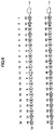
- FIG. 6 shows arrows indicating the congestion degrees extracted in accordance with the vehicle speeds.
- FIG. 6(a) shows the slow-state congestion degree.
- FIG. 6(b) shows the fast-state congestion degree.
- the numbers above each arrow indicate the vehicle speeds, and the numbers within each arrow indicate the congestion degrees extracted in accordance with the vehicle speeds.
- the numbers 1 to 20 at the top indicate the order of acquisition of the vehicle speed.
- Such information about the vehicle speed and congestion degree may be stored in the RAM of the probe ECU 12 or in a part of the map data storing unit 15 as vehicle information.
- the congestion degree is determined based on the vehicle speed at individual points, rather than an average speed.
- traffic information can be generated by distinguishing the influence of a congestion from that of the traffic signal.
- step S2 based on the congestion degrees extracted by the linked-congestion determination unit 12b in step S1, intermittent congestions are replaced by a continuation of a congestion degree.
- the "slow-state congestion degree” refers to the four levels of congestion; i.e., CD's I (extreme congestion), II (heavy congestion), III (intermediate congestion), and IV (light congestion).
- step 2 when a congestion degree equal to or higher than a particular congestion degree reappears within a predetermined distance, the in-between congestion degrees are replaced with the particular congestion degree within the predetermined distance.
- the "fast-state congestion degree” refers to CD VI (absolutely no congestion). In accordance with the present embodiment, if CD VI reappears within a predetermined distance, CD VI is allocated to a relevant interval.
- Such "predetermined distance" in step S2 is registered in the parameter table 16 of FIG. 5 as a "linked-congestion determination distance" for each road type in advance.
- a "linked-congestion determination distance” for each road type is registered in the parameter table 16 of FIG. 5 as a "linked-congestion determination distance" for each road type in advance.
- CD IV light congestion
- CD V no congestion
- CD IV reappears within the linked-congestion determination distance L2 (m)
- the intervening duration of CD V is replaced with CD IV.
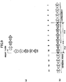
- FIG. 7 illustrates how the congestion degrees are replaced by the linked-congestion determination unit 12b.
- FIG. 7(a) corresponds to the slow-state congestion degree shown in FIG. 6(a) .
- FIG. 7(b) corresponds to the fast-state congestion degree shown in FIG. 6(b) .
- the linked-congestion determination distance L2 corresponds to a travel distance constituted by three arrows. Thus, if an equal or greater congestion degree is detected within three arrows, the preceding (temporary) congestion degree(s) are replaced with an earlier congestion degree.
- CD IV light congestion
- CD V no congestion
- CD I extreme congestion
- CD III intermediate congestion
- CD II medium congestion
- CD I is once again detected.
- the congestion is reduced in the intervals of the 8th to 10th arrows, but it reappears within the linked-congestion determination distance.
- the congestion degrees in the 8th to 10th intervals are replaced with CD I (extreme congestion).
- FIG. 8(a) shows an example of the relationship between travel distance and vehicle speed in a case where the slow-state congestion degree is detected.
- a congestion range in the interval of travel distances between about 300 m and about 1300 m (hereafter referred to as a congestion range).
- low vehicle speeds are intermittently detected.
- the congestion degree generating unit 12a extracts either CD I, II, III, or IV from the congestion range.
- CD VI absolute no congestion
- CD V no congestion
- CD IV light congestion
- CD V no congestion
- the vehicle speed in the 10th arrow is associated with CD VI (absolutely no congestion).
- CD VI absolute no congestion
- CD V no congestion
- CD VI absolute no congestion
- the fast-state congestion degree refers to the state of traffic even lighter than CD V (no congestion).
- any congestion degree that may temporarily exist among CD VI presumably reflects a deceleration to avoid collision with another vehicle in front waiting to turn right, for example, and thus does not indicate the actual congestion degree appropriately.
- the fast-state congestion degree can be accurately detected.
- the vehicle speed of the vehicle is detected at regular intervals of distance (or time). As a result, the vehicle speed at the time of deceleration for a right or left turn is also detected. Consequently, the vehicle speed may be lowered even if there is no congestion. If congestion degrees are linked on the basis of the vehicle speeds at the time of deceleration due to a right or left turn, the congestion degrees before or after the right or left turn may be erroneously replaced. Therefore, in accordance with the present embodiment, the congestion degrees are not linked at the time of a right or left turn.
- FIG. 9(a) shows an example of congestion degrees detected at the time of a right turn.
- the congestion degrees before and after the right turn are regarded as separate groups so that these congestion degrees are not linked by the linked-congestion determination unit 12b even if the aforementioned conditions are met.
- the linked-congestion determination unit 12b may determine that the vehicle made a right turn or a left turn if the angle made by the links before and after the direction change is equal to or greater than a predetermined angle. Upon detection of the right turn or the left turn, the location of the right turn or the left turn is saved in the vehicle information.
- FIG. 9(b) shows an example of congestion degrees in a case where a vehicle travels across a general road and an expressway.
- CD II (heavy congestion) is extracted.
- CD V no congestion is extracted. While CD V (no congestion) needs to be within the linked-congestion determination distance if the arrows are to be linked in accordance with CD II, the road types differ at the boundary between the 8th and 9th arrows in FIG. 9(b) . In this case, in accordance with the present embodiment, the linked-congestion determination distance is adjusted depending on a road type ratio.
- the parameter table 16 indicates that the linked-congestion determination distance for the general road and the expressway associated with CD II is L2 and L4, respectively.
- the linked-congestion determination distance of a section straddling both i.e., the section between the 5th and 10th arrows
- Linked ⁇ congestion determination distance L 2 ⁇ A / A + B + L 4 ⁇ B / A + B
- the thus linked congestion degrees may be stored in the RAM of the probe ECU 12 or a part of the map data storing unit 15 as vehicle information.
- step S3 the congestion degree recognition determination unit 12c considers congestions as a single continuous congestion and discards short congestions from the linked congestion degree.
- step S2 If an isolated congestion appears after the linking process in step S2, such isolated congestion presumably reflects more often a temporary decrease or increase in the vehicle speed than an actual congestion or a high-speed running status. Thus, when the distance in which a congestion degree continues is less than a predetermined distance, the congestion degree at the relevant location is discarded and replaced with CD V (no congestion).
- the congestion degree recognition determination unit 12c when the same congestion degrees continue, considers them as a single continuation of the congestion degree. When congestions of different congestion degrees continue, the congestion degree recognition determination unit 12c handles them as if they were a single continuation in the case of the slow-state congestion degree, even if there is a congestion with a slower vehicle speed among them. For example, when CD I (extreme congestion) appears between CD's IV (light congestion), this is regarded as a continuation of CD IV (light congestion).
- the slow-state congestion degree includes the four levels of CD's IV (light congestion), III (intermediate congestion), II (heavy congestion), and I (extreme congestion)
- this congestion is discarded.
- step 3 In other words, in step 3,
- the fast-state congestion degree refers to the single level of CD VI (absolutely no congestion).
- the "predetermined distance" in step S3 is registered in the parameter table 16 shown in FIG. 5 in advance as a congestion degree recognition determination value for each road type. For example, in the case of the general road associated with CD IV (light congestion), when the congestion degree recognition determination value is less than L3 (m), CD IV is discarded and replaced by CD V (no congestion).
- FIG. 8(b) shows an example of the relationship between travel distance and vehicle speed in a case where the slow-state congestion degree is detected.
- a section b1 includes the heavily congested areas adjacent the two sections b2 of the lightly congested areas, and an area with CD V (no congestion) between the heavily congested areas.
- the heavily congested areas are short (less than the congestion degree recognition determination value) and are therefore invalid.
- the lightly congested areas are equal to or greater than the congestion degree recognition determination value and are therefore invalid.
- FIG. 8(c) shows another example of the relationship between travel distance and vehicle speed in a case where the slow-state congestion degree is detected in a part of CD V (no congestion).
- the speed drop is only present at the position of distance C. Because this vehicle speed decrease is present over such a short distance alone and is less than the congestion degree recognition determination value, none of CD's IV, III, II, and I is recognized. Therefore, the speed decrease is discarded. By such processing, temporary stops made at the signals can be eliminated.
- FIGs. 10(a) and (b) illustrate how the congestion degree recognition determination unit 12c discards a short duration of a congestion degree and considers a series of arrows as a continuation of a certain congestion degree.
- FIG. 10(a) concerns the slow-state congestion degree
- FIG. 10(b) concerns the fast-state congestion degree.
- the congestion degrees illustrated in FIGs. 10(a) and (b) are different from those of FIG. 6 or 7 .
- the congestion degree recognition determination value L3 is set such that a congestion degree that lasts for less than three arrows is discarded.
- CD IV light congestion
- the continuation distance of the congestion degree is less than the congestion degree recognition determination value.
- the 5th vehicle arrow is discarded, and the 1st to 11th arrows are considered to constitute a continuation of CD V (no congestion).
- the 13th to 15th arrows indicate CD I (extreme congestion), and therefore they are considered to be a continuation of CD I.
- the 16th arrow indicates CD II (heavy congestion), and the adjacent 13th to 15th arrows indicate a congestion degree of a lower vehicle speed. Thus, the 13th to 16th arrows are considered to be a continuation of CD II (heavy congestion).
- the 17th arrow indicates CD III (intermediate congestion), and the adjacent 12th to 16th arrows indicate the same congestion degree or lower vehicle speeds. Thus, the 12th to 17th arrows are handled as a continuation of CD III (intermediate congestion).
- the 18th arrow indicates CD IV (light congestion), and the adjacent 12th to 17th arrows indicate congestion degrees of the lower vehicle speeds. Thus, the 12th to 18th arrows are handled as a continuation of CD IV (light congestion).
- a congestion degree considered to be continuous is compared with each congestion degree recognition determination value, and the congestion degrees that are equal to or greater than the congestion degree recognition determination value are finally considered to be continuous. If plural congestion degrees are extracted, heavier congestion degrees are preferentially continued.
- the 13th to 15th arrows are considered to constitute a continuation of CD I (extreme congestion).
- CD VI absolute no congestion
- the 14th to 18th arrows indicate CD VI (absolutely no congestion). Because their continuation distance is equal to or greater than the congestion degree recognition determination value, the 14th to 18th arrows are not discarded and instead regarded as a continuation.
- congestion degrees are not regarded as a continuation at the time of a right or left turn. This is to avoid the false determination of a continuous congestion due to the vehicle speeds at the time of deceleration during a right or left turn, for example.
- the congestion degree recognition determination value is registered on a road type basis, arrangements must be made concerning which congestion degree recognition determination value should be applied when a vehicle travels across roads of different road types.
- the congestion degree recognition determination value is adjusted depending on the road type ratio.
- the congestion degree recognition determination values in the case of the general road and the expressway associated with CD II are L3 and L5, respectively.
- the congestion degrees that are discarded or considered to be continuous may be stored in the RAM of the probe ECU 12 or in a part of the map data storing unit 15 as vehicle information.
- step S4 the link allocating unit 12d allocates the congestion degrees after the congestion degree recognition determination to the links.
- a congestion degree can be detected on a link by link basis.
- the congestion degree of a link may be the same for the single entire link, or a single link may contain several congestion degrees.
- the link allocating unit 12d generates two types of congestion degrees: one is a congestion degree (hereafter referred to as a "representative congestion degree") for the link as a whole; the other is a partial congestion degree that indicates an individual congestion degree within one link.
- the need to generate the partial congestion degree is low; therefore, a partial congestion degree is generated in cases where the link length is equal to or greater than a predetermined distance.
- the congestion degree in the link is uniform, no partial congestion degree is generated.
- the "predetermined distance" in step S4 is registered in the parameter table 16 of FIG. 5 in advance as a partial congestion link length for each road type.
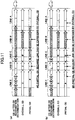
- FIGs. 11(a) and (b) illustrate how the link allocating unit 12d generates the representative congestion degree and the partial congestion degree.
- FIG. 11(a) concerns a case where each link length is greater than the partial congestion link length.
- FIG. 11(b) concerns a case where each link length is smaller than the partial congestion link length. While both FIGs. 11(a) and (b) concern the slow-state congestion degree, the fast-state congestion degree can be processed in the same manner.
- the congestion degrees at the top of FIG. 11(a) correspond to the congestion degrees after the congestion degree recognition determination in step S3, where the congestion degrees are divided by links A to E. Because link A includes CD's I (extreme congestion) and V (no congestion), the link allocating unit 12d generates a representative congestion degree for link A from the two congestion degrees. For the calculation of the representative congestion degree, a variety of statistical processes involving average values, median values, and so on, may be employed. In accordance with the present embodiment, the representative congestion degree is generated based on a harmonic average.
- the harmonic average of link A is CD I (extreme congestion).
- link B has CD V (no congestion) throughout, CD V (no congestion) is given as its representative congestion degree.
- CD V no congestion
- Link C based on a harmonic average of CD's V (no congestion) and III (intermediate congestion), CD IV (light congestion) is given as its representative congestion degree.
- link D the congestion degree is constant at CD I (extreme congestion); thus, CD I is given as its representative congestion degree.
- link E based on a harmonic average of CD's I (extreme congestion), II (heavy congestion), III (intermediate congestion), IV (light congestion), and V (no congestion), CD II (heavy congestion) is given as its representative congestion degree.
- the link allocating unit 12d in principle, generates the partial congestion degrees using the congestion degrees after the congestion degree recognition determination. Upon detection of successive congested states (of either CD I, II, III, or IV), they are considered to constitute a single congestion section, and the partial congestion degree for that section is generated based on a harmonic average.
- CD's I (extreme congestion) and V (no congestion) constitute its partial congestion degrees.
- link B there is no partial congestion degree.
- CD's V (no congestion) and III intermediate congestion
- link D there is no partial congestion degree.
- link E because CD's I, II, III, and IV are detected successively, these congestion degrees are considered to constitute a single congestion section, while CD V (no congestion) constitutes a partial congestion degree.
- the partial congestion degree of the integrated single congestion section is CD II (heavy congestion) based on a harmonic average.
- the representative congestion degrees and the partial congestion degrees allocated to the links may be stored in the RAM of the probe ECU 12 or in a part of the map data storing unit 15 as vehicle information.
- step S5 the congestion location grouping unit 12e and the link end correcting unit 12f generate more accurate traffic information using vehicle information about individual vehicles.
- the congestion location differs depending on the stop position of an individual vehicle.
- vehicle information about plural vehicles is used to correct errors caused by the position of each vehicle.
- each vehicle 2 transmits vehicle information to the vehicle information server 5 so that the vehicle information server 5 can generate traffic information.
- the link end may be corrected by the probe ECU 12 of each vehicle.
- the probe ECU 12 may be configured to transmit and receive inter-vehicle information using any of the known inter-vehicle communications or road-to-vehicle communications technologies.
- step S4 the representative congestion degree is obtained on a link by link basis.
- each of the vehicles When plural vehicles travel along the same link, each of the vehicles generates the representative congestion degree.
- FIG. 12(a) shows the representative congestion degrees for the same link generated by plural vehicles.
- vehicle A detects CD IV (light congestion);
- vehicle B detects CD I (extreme congestion);
- vehicle C detects CD II (heavy congestion);
- vehicle D detects CD V (no congestion); and
- vehicle E detects CD II (heavy congestion).
- the congestion location grouping unit 12e generates the congestion degree for the link by calculating a harmonic average as follows:
- Statistical value Number of samples / 1 / CD IV + 1 / CD I + 1 / CD II + 1 / CD V + 1 / CD II
- the statistical value is CD II (heavy congestion).
- the congestion location grouping unit 12e generates detailed congestion degrees within the link from the vehicle information about the plural vehicles.
- the congestion location grouping unit 12e groups partially congested locations in the link based on a head position and a tail position of each partial congestion of each vehicle.
- FIG. 12(b) shows the partial congestion degrees generated from the vehicle information about the plural vehicles and how they are grouped.
- the congestion location grouping unit 12e superposes the partial congestion degrees of the individual vehicles, and divides the overlapping congestion locations into the same congestion group.
- vehicle A has two partial congestion degree sections A1 and A2 of CD I (extreme congestion).
- Vehicle B has the partial congestion degree section B1 of CD I (extreme congestion).
- Vehicle C has the partial congestion degree section C1 of CD II (heavy congestion).
- Vehicle D has the two partial congestion degree sections D1 and D2 of CD I (extreme congestion).
- the congestion location grouping unit 12e groups the overlapping congestion locations between a front end (A2) and a rear end (D2) into a single partial congestion group.
- partial congestion groups 1 and 2 are obtained.
- FIG. 12(c) shows an example in which, although the vehicles have congestion locations as in the example of FIG. 12(b) , the congestion location C1 of vehicle C has no overlaps with the congestion location of any of the other vehicles.
- the congestion location grouping unit 12e does not group the partial congestion degrees of the plural vehicles. In this way, the grouping of the entire link into a congestion location group due to the linking of the individual congestion locations can be prevented.
- a group with a greater number of samples i.e., the vehicles detected as congestion locations
- a group with a longer congestion location is preferentially adopted.
- the head position, the tail position, and the congestion degree of a congestion are determined as follows:
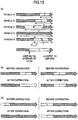
- FIG. 13(a) illustrates how the head position, the tail position, and the congestion degree of a partial congestion group are determined.
- the tail position of the congestion by vehicle A is a (m) from the link terminal end.
- the tail position of the congestion by vehicle B is b (m) from the link terminal end.
- the tail position of the congestion by vehicle C is c (m) from the link terminal end.
- the tail position of the congestion by vehicle E is e (m) from the link terminal end.
- the congestion tail position can be determined from an arithmetic average of a, b, c, and e.
- the "link terminal end" refers to the front end of the arrow.
- the result of the harmonic-averaging is CD I (extreme congestion).
- the link end correcting unit 12f corrects the congestion degree at the link end of the partial congestion degree.
- the representative congestion degree there is no need for correction of the link end because the congestion degree is uniform throughout the link.
- the link end is corrected after the congestion degrees of plural vehicles are grouped.
- the link end may be corrected directly in the partial congestion degree of each vehicle.
- the link end correcting unit 12f substitutes an adjacent congestion degree for a congestion degree located within a predetermined distance of the link terminal end.
- the "predetermined distance" in step S5 is registered in the parameter table 16 of FIG. 5 in advance as a link end correction range.
- the correction of the link end is required in principle for a link that includes a traffic signal.
- the link end correction range is registered with regard to the general road alone.
- CD I extreme congestion
- the congestion degree up to the link terminal end is substituted by CD I.
- the congestion degree up to the link terminal end is substituted by CD I.
- no congestion degree is detected within the link end correction range from the link terminal end.
- no substitution of congestion degree is performed.
- the vehicle speed may be increased because the vehicle, having been waiting for the signal, is not the leading vehicle.
- the congestion more often than not continues up to the link terminal end.
- the link end correcting unit 12f if the head position of the partial congestion is within the predetermined distance of the link beginning end, discards the relevant partial congestion degree.
- CD I extreme congestion
- CD I extreme congestion
- a congestion degree is detected beyond the link end correction range from the link beginning end.
- the congestion degree is not discarded.
- a congestion may often be caused by the low vehicle speed due to the insufficient acceleration of the vehicle that has been waiting for the signal in in the preceding link.
- a false congestion at the link beginning end can be removed.
- the possible congestion position and congestion degree of an individual vehicle can be smoothed, so that accurate traffic information for the relevant link can be generated.
- the influences of the stops made for the traffic signals or the instantaneous vehicle speed changes can be removed.
- accurate traffic information can be generated by taking advantage of the vehicle speed information collected by the probe car.
Landscapes
- Physics & Mathematics (AREA)
- Engineering & Computer Science (AREA)
- General Physics & Mathematics (AREA)
- Theoretical Computer Science (AREA)
- Chemical & Material Sciences (AREA)
- Analytical Chemistry (AREA)
- Radar, Positioning & Navigation (AREA)
- Remote Sensing (AREA)
- Educational Technology (AREA)
- Educational Administration (AREA)
- Business, Economics & Management (AREA)
- Mathematical Physics (AREA)
- Computer Hardware Design (AREA)
- Ecology (AREA)
- Life Sciences & Earth Sciences (AREA)
- General Engineering & Computer Science (AREA)
- Traffic Control Systems (AREA)
- Navigation (AREA)
- Instructional Devices (AREA)
Claims (19)
- Verkehrsinformationserzeugungsverfahren zur Erzeugung von Verkehrsinformation bezüglich einer Straße, auf der sich ein Fahrzeug (2) fortbewegt, wobei das Verfahren umfasst
einen Fahrzeuggeschwindigkeitserfassungsschritt eines Erfassens einer Fahrzeuggeschwindigkeit des Fahrzeugs bei vorbestimmten Distanz- oder Zeitintervallen unter Verwendung eines Fahrzeuggeschwindigkeitssensors (11), und
einen Verstopfungsgraderfassungsschritt einer Verstopfungsgraderfassungseinheit (12a), der einen Verstopfungsgrad erfasst, der mit der Fahrzeuggeschwindigkeit verknüpft ist, durch Bezugnahme auf eine festgelegte Geschwindigkeit und eine festgelegte Distanz, die in Verbindung mit dem Verstopfungsgrad vorbestimmt sind, und eine Verbindungsbestimmungsdistanz, die gemäß einem Straßentyp festgelegt ist. - Verkehrsinformationserzeugungsverfahren nach Anspruch 1, wobei der Verstopfungsgraderfassungsschritt ein Erfassen des Verstopfungsgrads umfasst, der auf eine Verstopfung hinweist, wenn die Fahrzeuggeschwindigkeit für eine Distanz gleich oder größer als die festgelegte Distanz kontinuierlich unter der festgelegten Geschwindigkeit ist,wobei der Verstopfungsgraderfassungsschritt den Verstopfungsgrad erfasst, der auf eine Hochgeschwindigkeitsstraße hinweist, wenn die Fahrzeuggeschwindigkeit für eine Distanz gleich oder größer als die festgelegte Distanz kontinuierlich gleich oder größer als die festgelegte Geschwindigkeit ist.
- Verkehrsinformationserzeugungsverfahren nach Anspruch 1 oder 2, wobei der Verstopfungsgraderfassungsschritt ein Bestimmen umfasst, dass die Fahrzeuggeschwindigkeit zwischen einem ersten Punkt, bei dem die Fahrzeuggeschwindigkeit gleich wie oder größer als die festgelegte Geschwindigkeit wird, und einem zweiten Punkt, der innerhalb der Verbindungsbestimmungsdistanz von dem ersten Punkt liegt, geringer als die festgelegte Geschwindigkeit ist, wenna) die Fahrzeuggeschwindigkeit bei dem zweiten Punkt geringer als die festgelegte Geschwindigkeit ist,
wobei der Verstopfungsgraderfassungsschritt bestimmt, dass die Fahrzeuggeschwindigkeit zwischen einem ersten Punkt, bei dem die Fahrzeuggeschwindigkeit unter die festgelegte Geschwindigkeit fällt, und einem zweiten Punkt, der innerhalb der Verbindungsbestimmungsdistanz von dem ersten Punkt liegt, gleich wie oder größer als die festgelegte Geschwindigkeit ist, wennb) die Fahrzeuggeschwindigkeit an dem zweiten Punkt gleich wie oder größer als die festgelegte Geschwindigkeit ist. - Verkehrsinformationserzeugungsverfahren nach Anspruch 3, wobei der Verstopfungsgraderfassungsschritt ein Bestimmen umfasst, dass die Fahrzeuggeschwindigkeit zwischen dem ersten Punkt und dem zweiten Punkt nicht geringer als die festgelegte Geschwindigkeit ist, wenn die Bedingung a) erfüllt ist, oder dass die Fahrzeuggeschwindigkeit zwischen dem ersten Punkt und dem zweiten Punkt nicht gleich wie oder größer als die festgelegte Geschwindigkeit ist, wenn die Bedingung b) erfüllt ist, in einem Fall, in dem das Fahrzeug (2) eine Rechtswendung oder eine Linkswendung zwischen dem ersten Punkt und dem zweiten Punkt vollführt.
- Verkehrsinformationserzeugungsverfahren nach einem der Ansprüche 1 bis 4,wobei der Verstopfungsgraderfassungsschritt einen Fortsetzungsschritt eines Ungültigmachens des Verstopfungsgrads umfasst, der gemäß der Verbindungsbestimmungsdistanz verbunden ist, wenn der verbundene Verstopfungsgrad nicht für eine Distanz gleich wie oder größer als die festgelegte Distanz fortgesetzt ist.
- Verkehrsinformationserzeugungsverfahren nach einem der Ansprüche 1 bis 5,wobei die festgelegte Distanz und die Verbindungsbestimmungsdistanz gemäß einem Straßentyp festgelegt sind, undwobei die festgelegte Distanz und die Verbindungsbestimmungsdistanz gemäß einem Straßentypverhältnis bei einem Punkt, an dem sich das Fahrzeug (2) von einem Straßentyp zu einem anderen fortbewegt, geändert werden.
- Verkehrsinformationserzeugungsverfahren nach einem der Ansprüche 1 bis 6, ferner mit einem Zuordnungsschritt einer Zuordnungseinheit (12d), der eine Verbindung von einer Straßenkartenspeichereinheit (15) extrahiert, bei der eine Straßenkarte der Straße gespeichert ist, wobei die Zuordnungseinheit (12d) den gemäß der Verbindungsbestimmungsdistanz verbundenen Verstopfungsgrad der Verbindung zuordnet.
- Verkehrsinformationserzeugungsverfahren nach Anspruch 7, ferner mit den Schritten, dassdie Zuordnungseinheit (12d) einen Teilverstopfungsgrad erzeugt, wobei eine Vielzahl der Verstopfungsgrade einem Link zugeordnet werden, der eine Länge gleich wie oder größer als eine bestimmte Teilverstopfungsgraderzeugungsverbindungslänge hat, undeine Verbindungsendenkorrektureinheit (12f) auf einen festgelegten Verbindungskorrekturbereich Bezug nimmt und den Verstopfungsgrad bis zu dem Verbindungsabschlussende oder dem Verbindungsstartende korrigiert, wenn der Teilverstopfungsgrad mehr in Richtung des Verbindungsabschlussendes oder des Verbindungsstartendes als der Verbindungsendenkorrekturbereich zugeordnet ist.
- Verkehrsinformationserzeugungsverfahren nach einem der Ansprüche 1 bis 8,wobei der Verstopfungsgrad mehrere Pegel aufweist, die mit einer Vielzahl der festgelegten Geschwindigkeiten verknüpft sind.
- Verkehrsinformationserzeugungsverfahren nach einem der Ansprüche 1 bis 9 mit einem Erzeugen der Verkehrsinformation unter Verwendung eines fahrzeugseitigen Geräts (10), das an dem Fahrzeug (2) montiert ist.
- Verkehrsinformationserzeugungsverfahren nach Anspruch 8, miteinem Verbinden des Fahrzeugs (2) mit einem Fahrzeuginformationsserver (5) mittels eines Netzwerks (4),einem Übertragen der Fahrzeuginformation von dem Fahrzeug (2) zu dem Fahrzeuginformationsserver (5) mittels des Netzwerks (4), undeinem Erzeugen der Verkehrsinformation unter Verwendung des Verkehrsinformationsservers (5).
- Verkehrsinformationserzeugungsverfahren nach Anspruch 11, mit den durch die Verbindungsendenkorrektureinheit (12f) durchgeführten Schritteneines Empfangens der Fahrzeuginformation von einer Vielzahl von Fahrzeugen,eines Gruppierens der Teilverstopfungsgrade der mehreren Fahrzeuge bezüglich der gleichen Verbindung, undeines Berechnens des Verstopfungsgrads in Form eines statistischen Werts der Teilverstopfungsgrade in jeder Gruppe.
- Verkehrsinformationserzeugungsverfahren nach Anspruch 12, wobei der Teilverstopfungsgrad, an dem eine Anzahl von Fahrzeugen geringer als eine vorbestimmte Anzahl teilhat, nicht gruppiert wird.
- Verkehrsinformationserzeugungsverfahren nach Anspruch 12, wobei, wenn es eine Vielzahl der Gruppen gibt, die Gruppe mit einer größeren Anzahl von Fahrzeugen bevorzugt übernommen wird.
- Verkehrsinformationserzeugungsverfahren nach Anspruch 14, wobei, wenn es zwei oder mehr Gruppen gibt, die die gleiche Anzahl von Fahrzeugen aufweisen, die längste Gruppe bevorzugt übernommen wird.
- Verkehrsinformationserzeugungsverfahren nach einem der Ansprüche 1 bis 15, wobei die Verbindungsbestimmungsdistanz gemäß dem Verstopfungsgrad bei dem Straßentyp eingestellt wird.
- Elektronische Steuereinheit (12), die dazu eingerichtet ist, um Verkehrsinformation bezüglich einer Straße zu erzeugen, auf der sich ein Fahrzeug (2) fortbewegt, miteiner Verstopfungsgraderfassungseinheit (12a), die dazu eingerichtet ist, um einen Verstopfungsgrad gemäß einer durch einen Fahrzeuggeschwindigkeitssensor (11) bei vorbestimmten Distanz- oder Zeitintervallen erfassten Fahrzeuggeschwindigkeit durch Bezugnahme auf eine festgelegte Geschwindigkeit und eine festgelegte Distanz, die gemäß dem Verstopfungsgrad festgelegt sind, und eine Verbindungsbestimmungsdistanz, die gemäß einem Straßentyp festgelegt ist, zu erfassen.
- Verkehrsinformationserzeugungsvorrichtung (10), die dazu eingerichtet ist, um Verkehrsinformation bezüglich einer Straße, auf der sich ein Fahrzeug (2) fortbewegt, zu erzeugen, wobei die Vorrichtung umfassteine elektronische Steuereinheit (12) gemäß Anspruch 17, wobeider Fahrzeuggeschwindigkeitssensor (11) ein fahrzeugseitiger Fahrzeuggeschwindigkeitssensor ist.
- Navigationssystem (100), miteiner Kartendatenspeichereinheit (15), die dazu eingerichtet ist, um eine Straßenkarte einer Straße zu speichern, auf der sich ein Fahrzeug (2) fortbewegt,einer Positionierungseinheit (14), die dazu eingerichtet ist, um eine Position des Fahrzeugs (2) unter Verwendung einer durch einen künstlichen Satelliten ausgestrahlten Radiowelle zu bestimmen,einer elektronischen Steuereinheit (12) gemäß Anspruch 17, undeiner Anzeigeeinheit (17), die dazu eingerichtet ist, um die Verkehrsinformation, die durch die elektronische Steuereinheit (12) erzeugt ist, zusammen mit der Straßenkarte anzuzeigen.
Applications Claiming Priority (2)
| Application Number | Priority Date | Filing Date | Title |
|---|---|---|---|
| JP2006189561A JP4342535B2 (ja) | 2006-07-10 | 2006-07-10 | 渋滞度作成方法、渋滞度作成装置 |
| PCT/JP2007/063725 WO2008007663A1 (fr) | 2006-07-10 | 2007-07-10 | Procédé et dispositif de création d'information de trafic, affichage, système de navigation et unité de commande électronique |
Publications (3)
| Publication Number | Publication Date |
|---|---|
| EP2040236A1 EP2040236A1 (de) | 2009-03-25 |
| EP2040236A4 EP2040236A4 (de) | 2015-01-21 |
| EP2040236B1 true EP2040236B1 (de) | 2017-05-31 |
Family
ID=38923222
Family Applications (1)
| Application Number | Title | Priority Date | Filing Date |
|---|---|---|---|
| EP07790543.8A Not-in-force EP2040236B1 (de) | 2006-07-10 | 2007-07-10 | Verfahren und vorrichtung zur generierung von verkehrsinformationen, anzeige, navigationssystem und elektrische steuereinheit |
Country Status (7)
| Country | Link |
|---|---|
| US (1) | US8744735B2 (de) |
| EP (1) | EP2040236B1 (de) |
| JP (1) | JP4342535B2 (de) |
| KR (1) | KR101031195B1 (de) |
| CN (1) | CN101490730B (de) |
| ES (1) | ES2638142T3 (de) |
| WO (1) | WO2008007663A1 (de) |
Families Citing this family (35)
| Publication number | Priority date | Publication date | Assignee | Title |
|---|---|---|---|---|
| JP4938591B2 (ja) | 2007-08-22 | 2012-05-23 | トヨタ自動車株式会社 | 交通情報作成方法、交通情報作成装置及びナビゲーションシステム |
| JP4957639B2 (ja) * | 2008-04-25 | 2012-06-20 | 株式会社デンソー | 車載装置及びセンター装置 |
| JP2010016559A (ja) * | 2008-07-02 | 2010-01-21 | Denso Corp | 暗号通信システム、受信装置、及び、送信装置 |
| JP5298712B2 (ja) * | 2008-09-04 | 2013-09-25 | 住友電気工業株式会社 | 感知器異常検出システム、方法、感知器異常検出装置及びコンピュータプログラム |
| JP4998504B2 (ja) * | 2009-04-07 | 2012-08-15 | 住友電気工業株式会社 | プローブ情報生成装置及び方法 |
| JP5460869B2 (ja) * | 2010-06-29 | 2014-04-02 | 本田技研工業株式会社 | 渋滞予測装置 |
| JP5555778B2 (ja) * | 2010-12-15 | 2014-07-23 | 本田技研工業株式会社 | 渋滞予測方法 |
| JP5513361B2 (ja) * | 2010-12-24 | 2014-06-04 | 株式会社ゼンリンデータコム | 渋滞情報生成装置、渋滞情報生成方法、及びプログラム |
| US8711005B2 (en) | 2010-12-27 | 2014-04-29 | Nicholas R. Musachio | Variable speed traffic control system |
| JP5386474B2 (ja) * | 2010-12-28 | 2014-01-15 | 三菱重工業株式会社 | 情報処理装置、料金収受システム、及び料金収受方法 |
| CN102571886B (zh) * | 2010-12-31 | 2016-04-20 | 上海博泰悦臻电子设备制造有限公司 | 车载终端的在线状态检测方法及系统 |
| JP5648009B2 (ja) * | 2012-03-21 | 2015-01-07 | アイシン・エィ・ダブリュ株式会社 | 交通情報作成装置、交通情報作成方法及びプログラム |
| JP2012150843A (ja) * | 2012-05-15 | 2012-08-09 | Sumitomo Electric Ind Ltd | プローブ情報生成装置及び方法 |
| JP6063237B2 (ja) * | 2012-12-11 | 2017-01-18 | 株式会社エヌ・ティ・ティ・データ | 渋滞予測装置、渋滞予測システム、渋滞予測方法、及び、プログラム |
| CN104969274B (zh) * | 2013-02-01 | 2017-03-08 | 日立汽车系统株式会社 | 行驶控制装置和行驶控制系统 |
| CN104252778B (zh) * | 2013-06-28 | 2016-08-10 | 中国科学院微电子研究所 | 交通信息的采集、处理、发布方法 |
| US10692370B2 (en) * | 2014-03-03 | 2020-06-23 | Inrix, Inc. | Traffic obstruction detection |
| WO2015145637A1 (ja) * | 2014-03-26 | 2015-10-01 | パイオニア株式会社 | 渋滞判定装置、渋滞判定方法、渋滞判定プログラム、端末装置、渋滞情報表示方法、及び、渋滞情報表示プログラム |
| CN105723242B (zh) * | 2014-08-26 | 2018-07-03 | 微软技术许可有限责任公司 | 测量路网中的交通速度 |
| GB201415731D0 (en) * | 2014-09-05 | 2014-10-22 | Tom Tom Int Bv | Methods and systems for generating flow data |
| CN104482936B (zh) * | 2014-12-23 | 2018-10-26 | 西安三星电子研究有限公司 | 提供路况信息的云端服务器和显示路况信息的装置 |
| CN105551243A (zh) * | 2015-12-04 | 2016-05-04 | 镇江金山交通信息科技有限公司 | 交通信息评估方法 |
| JP6472374B2 (ja) | 2015-12-22 | 2019-02-20 | 本田技研工業株式会社 | ナビサーバおよびナビシステム |
| KR20180039892A (ko) * | 2016-10-11 | 2018-04-19 | 현대자동차주식회사 | 내비게이션 장치, 이를 포함하는 차량 및 차량의 제어방법 |
| US11024166B2 (en) * | 2016-12-21 | 2021-06-01 | Here Global B.V. | Method, apparatus, and computer program product for estimating traffic speed through an intersection |
| JP6661563B2 (ja) * | 2017-03-02 | 2020-03-11 | 株式会社ゼンリンデータコム | 解析装置及び解析方法 |
| US10210755B1 (en) * | 2018-05-07 | 2019-02-19 | International Business Machines Corporation | Cognitive traffic signal cycle timer |
| CN108717793A (zh) * | 2018-06-22 | 2018-10-30 | 泉州创先力智能科技有限公司 | 一种道路堵车监控方法、装置、设备和存储介质 |
| KR20200075122A (ko) * | 2018-12-12 | 2020-06-26 | 현대자동차주식회사 | 능동적 차량 제어 통지 방법 및 시스템 |
| JP2020095565A (ja) * | 2018-12-14 | 2020-06-18 | トヨタ自動車株式会社 | 情報処理システム、プログラム、及び情報処理方法 |
| CN114078327B (zh) * | 2020-08-20 | 2023-01-24 | 浙江宇视科技有限公司 | 道路拥堵状态检测方法、装置、设备和存储介质 |
| JP7812695B2 (ja) * | 2022-03-04 | 2026-02-10 | オムロン株式会社 | 交通状況推定装置、交通状況推定方法、および交通状況推定プログラム |
| CN115938105B (zh) * | 2023-02-21 | 2025-11-11 | 福建理工大学 | 一种基于etc大数据的高速公路区段里程测量方法 |
| CN117315945B (zh) * | 2023-11-30 | 2024-03-01 | 长春汽车工业高等专科学校 | 一种基于大数据的交通碰撞事故车辆救援方法及系统 |
| US20250316160A1 (en) * | 2024-04-04 | 2025-10-09 | Toyota Motor Engineering & Manufacturing North America, Inc. | Methods and systems for estimating lane-level traffic jam using lane change signals of connected vehicles |
Family Cites Families (22)
| Publication number | Priority date | Publication date | Assignee | Title |
|---|---|---|---|---|
| JP2712844B2 (ja) * | 1990-04-27 | 1998-02-16 | 株式会社日立製作所 | 交通流計測装置及び交通流計測制御装置 |
| JP3240505B2 (ja) | 1996-07-05 | 2001-12-17 | 株式会社日立製作所 | 渋滞区間推定方法および渋滞区間推定装置 |
| WO2002007125A1 (de) | 2000-07-19 | 2002-01-24 | Volkswagen Aktiengesellschaft | Verfahren zur ermittlung von verkehrslageinformationen |
| DE10133001A1 (de) | 2000-07-19 | 2002-01-31 | Gedas Telematics Gmbh | Verfahren zur Ermittlung von Verkehrslageinformationen |
| JP2002090165A (ja) | 2000-09-14 | 2002-03-27 | Nissan Motor Co Ltd | 渋滞判定装置 |
| JP4074053B2 (ja) | 2000-09-14 | 2008-04-09 | パイオニア株式会社 | 渋滞状態判別装置、渋滞情報供給装置、渋滞状態判別システム、車載端末及び渋滞状態判別方法 |
| US6650948B1 (en) * | 2000-11-28 | 2003-11-18 | Applied Generics Limited | Traffic flow monitoring |
| JP3803710B2 (ja) * | 2001-05-17 | 2006-08-02 | 国土交通省国土技術政策総合研究所長 | 交通情報処理方法及び交通情報処理システム |
| JP3887558B2 (ja) * | 2001-11-08 | 2007-02-28 | 株式会社ケンウッド | ナビゲーションシステム、渋滞状況表示方法およびプログラム |
| JP3937011B2 (ja) | 2002-03-20 | 2007-06-27 | 国土交通省国土技術政策総合研究所長 | 交通情報処理方法及び交通情報処理システム |
| JP4255007B2 (ja) * | 2003-04-11 | 2009-04-15 | 株式会社ザナヴィ・インフォマティクス | ナビゲーション装置、およびその旅行時間算出方法 |
| US7355528B2 (en) * | 2003-10-16 | 2008-04-08 | Hitachi, Ltd. | Traffic information providing system and car navigation system |
| JP2005259116A (ja) | 2004-02-13 | 2005-09-22 | Matsushita Electric Ind Co Ltd | 交通情報算出装置、交通情報算出方法、交通情報表示方法および交通情報表示装置 |
| JP2005285108A (ja) * | 2004-03-03 | 2005-10-13 | Matsushita Electric Ind Co Ltd | 突発事象検出方法及び突発事象検出装置 |
| US7366606B2 (en) | 2004-04-06 | 2008-04-29 | Honda Motor Co., Ltd. | Method for refining traffic flow data |
| US7680596B2 (en) | 2004-04-06 | 2010-03-16 | Honda Motor Co., Ltd. | Route calculation method for a vehicle navigation system |
| JP2005301643A (ja) | 2004-04-12 | 2005-10-27 | Matsushita Electric Ind Co Ltd | 交通情報生成システム |
| JP2005316739A (ja) * | 2004-04-28 | 2005-11-10 | Sumitomo Electric Ind Ltd | 車両検出位置をリンクに対応付けする方法及び装置、渋滞箇所判定方法、渋滞箇所表示方法並びにプログラム |
| JP2006059058A (ja) * | 2004-08-19 | 2006-03-02 | Matsushita Electric Ind Co Ltd | 走行データ判定装置 |
| JP4444047B2 (ja) * | 2004-09-13 | 2010-03-31 | パナソニック株式会社 | 走行履歴収集システムおよび車載装置 |
| JP4582401B2 (ja) | 2004-11-22 | 2010-11-17 | 株式会社デンソー | 渋滞情報提供システム |
| JP2006189561A (ja) | 2005-01-05 | 2006-07-20 | Konica Minolta Business Technologies Inc | 画像形成装置及びその制御方法 |
-
2006
- 2006-07-10 JP JP2006189561A patent/JP4342535B2/ja not_active Expired - Fee Related
-
2007
- 2007-07-10 EP EP07790543.8A patent/EP2040236B1/de not_active Not-in-force
- 2007-07-10 ES ES07790543.8T patent/ES2638142T3/es active Active
- 2007-07-10 WO PCT/JP2007/063725 patent/WO2008007663A1/ja not_active Ceased
- 2007-07-10 KR KR1020087032077A patent/KR101031195B1/ko not_active Expired - Fee Related
- 2007-07-10 CN CN2007800261550A patent/CN101490730B/zh not_active Expired - Fee Related
- 2007-07-10 US US12/307,968 patent/US8744735B2/en not_active Expired - Fee Related
Also Published As
| Publication number | Publication date |
|---|---|
| KR20090028572A (ko) | 2009-03-18 |
| EP2040236A1 (de) | 2009-03-25 |
| US8744735B2 (en) | 2014-06-03 |
| JP4342535B2 (ja) | 2009-10-14 |
| JP2008020948A (ja) | 2008-01-31 |
| KR101031195B1 (ko) | 2011-04-26 |
| CN101490730A (zh) | 2009-07-22 |
| ES2638142T3 (es) | 2017-10-18 |
| CN101490730B (zh) | 2010-12-08 |
| US20090292456A1 (en) | 2009-11-26 |
| WO2008007663A1 (fr) | 2008-01-17 |
| EP2040236A4 (de) | 2015-01-21 |
Similar Documents
| Publication | Publication Date | Title |
|---|---|---|
| US8744735B2 (en) | Traffic information generating method, traffic information generating apparatus, display, navigation system, and electronic control unit | |
| US8433504B2 (en) | Traffic information generation method, traffic information generation device, and navigation system | |
| JP5024879B2 (ja) | 交通情報作成方法及び交通情報作成装置 | |
| JP4730165B2 (ja) | 交通情報管理システム | |
| EP2377111B1 (de) | Navigationsgerät, verfahren zur übertragung von sondeninformationen, computerlesbares speichermedium mit darauf gespeichertem programm zur übertragung von sondeninformationen sowie vorrichtung zur erzeugung von verkehrsinformationen | |
| US20040249562A1 (en) | Traffic information management system | |
| WO2005078679A1 (ja) | 交通情報算出装置、交通情報算出方法、交通情報表示方法及び交通情報表示装置 | |
| US8296047B2 (en) | Traffic information processing apparatus, traffic information management server, traffic information management system | |
| JP2011022649A (ja) | リンク旅行時間算出装置及びプログラム | |
| JP2003281674A (ja) | 交通情報処理方法及び交通情報処理システム | |
| EP1548405A1 (de) | System, Verfahren und Datastruktur für Mittelung der Navigationsdaten | |
| CN102592446B (zh) | 利用浮动车定位数据计算城际道路旅行时间的方法 | |
| JP5110125B2 (ja) | 情報処理装置及びコンピュータプログラム | |
| EP2287821B1 (de) | Verfahren und Vorrichtung zum Bestimmen von Verkehrsinformationen und System zur Routenberechnung | |
| JP3803710B2 (ja) | 交通情報処理方法及び交通情報処理システム | |
| JP2008158562A (ja) | 交通情報配信センタ、車両用プローブ装置、交通情報システム及び交通情報配信センタの交通情報配信方法 | |
| JP2003344074A (ja) | 情報提供システム | |
| JP2010230521A (ja) | 渋滞度情報送信装置、渋滞度情報送信方法および渋滞度情報送信プログラムならびに渋滞度情報受信装置 | |
| CN100472579C (zh) | 交通信息计算装置、交通信息计算方法、交通信息显示方法及交通信息显示装置 | |
| JP4766319B2 (ja) | ナビゲーション装置、ナビゲーション方法及びナビゲーションプログラム | |
| JP2002208094A (ja) | 交通情報収集・提供システム | |
| JP3851947B2 (ja) | 交通情報処理方法及び交通情報処理システム | |
| KR101060673B1 (ko) | 교통 정보 데이터 프레임 실행방법과 이를 저장하고 컴퓨터로 판독 가능한 기록매체 | |
| JP2011039587A (ja) | プローブ情報生成装置及びコンピュータプログラム | |
| JP2007108943A (ja) | 交通情報処理装置及び交通情報処理方法 |
Legal Events
| Date | Code | Title | Description |
|---|---|---|---|
| PUAI | Public reference made under article 153(3) epc to a published international application that has entered the european phase |
Free format text: ORIGINAL CODE: 0009012 |
|
| 17P | Request for examination filed |
Effective date: 20090108 |
|
| AK | Designated contracting states |
Kind code of ref document: A1 Designated state(s): AT BE BG CH CY CZ DE DK EE ES FI FR GB GR HU IE IS IT LI LT LU LV MC MT NL PL PT RO SE SI SK TR |
|
| AX | Request for extension of the european patent |
Extension state: AL BA HR MK RS |
|
| RBV | Designated contracting states (corrected) |
Designated state(s): DE ES FR GB IT |
|
| DAX | Request for extension of the european patent (deleted) | ||
| RAP1 | Party data changed (applicant data changed or rights of an application transferred) |
Owner name: AISIN AW CO., LTD. Owner name: TOYOTA JIDOSHA KABUSHIKI KAISHA |
|
| A4 | Supplementary search report drawn up and despatched |
Effective date: 20141218 |
|
| RIC1 | Information provided on ipc code assigned before grant |
Ipc: G09B 29/10 20060101ALI20141212BHEP Ipc: G08G 1/01 20060101AFI20141212BHEP Ipc: G09B 29/00 20060101ALI20141212BHEP Ipc: G08G 1/0969 20060101ALI20141212BHEP Ipc: G08G 1/13 20060101ALI20141212BHEP |
|
| 17Q | First examination report despatched |
Effective date: 20160627 |
|
| GRAP | Despatch of communication of intention to grant a patent |
Free format text: ORIGINAL CODE: EPIDOSNIGR1 |
|
| INTG | Intention to grant announced |
Effective date: 20161125 |
|
| GRAS | Grant fee paid |
Free format text: ORIGINAL CODE: EPIDOSNIGR3 |
|
| GRAA | (expected) grant |
Free format text: ORIGINAL CODE: 0009210 |
|
| AK | Designated contracting states |
Kind code of ref document: B1 Designated state(s): DE ES FR GB IT |
|
| REG | Reference to a national code |
Ref country code: GB Ref legal event code: FG4D |
|
| REG | Reference to a national code |
Ref country code: FR Ref legal event code: PLFP Year of fee payment: 11 |
|
| REG | Reference to a national code |
Ref country code: DE Ref legal event code: R096 Ref document number: 602007051173 Country of ref document: DE |
|
| REG | Reference to a national code |
Ref country code: ES Ref legal event code: FG2A Ref document number: 2638142 Country of ref document: ES Kind code of ref document: T3 Effective date: 20171018 |
|
| REG | Reference to a national code |
Ref country code: DE Ref legal event code: R097 Ref document number: 602007051173 Country of ref document: DE |
|
| PLBE | No opposition filed within time limit |
Free format text: ORIGINAL CODE: 0009261 |
|
| STAA | Information on the status of an ep patent application or granted ep patent |
Free format text: STATUS: NO OPPOSITION FILED WITHIN TIME LIMIT |
|
| 26N | No opposition filed |
Effective date: 20180301 |
|
| REG | Reference to a national code |
Ref country code: FR Ref legal event code: PLFP Year of fee payment: 12 |
|
| PGFP | Annual fee paid to national office [announced via postgrant information from national office to epo] |
Ref country code: FR Payment date: 20190619 Year of fee payment: 13 |
|
| PGFP | Annual fee paid to national office [announced via postgrant information from national office to epo] |
Ref country code: ES Payment date: 20190802 Year of fee payment: 13 Ref country code: IT Payment date: 20190719 Year of fee payment: 13 Ref country code: DE Payment date: 20190625 Year of fee payment: 13 |
|
| PGFP | Annual fee paid to national office [announced via postgrant information from national office to epo] |
Ref country code: GB Payment date: 20190710 Year of fee payment: 13 |
|
| REG | Reference to a national code |
Ref country code: DE Ref legal event code: R119 Ref document number: 602007051173 Country of ref document: DE |
|
| GBPC | Gb: european patent ceased through non-payment of renewal fee |
Effective date: 20200710 |
|
| PG25 | Lapsed in a contracting state [announced via postgrant information from national office to epo] |
Ref country code: FR Free format text: LAPSE BECAUSE OF NON-PAYMENT OF DUE FEES Effective date: 20200731 Ref country code: GB Free format text: LAPSE BECAUSE OF NON-PAYMENT OF DUE FEES Effective date: 20200710 |
|
| PG25 | Lapsed in a contracting state [announced via postgrant information from national office to epo] |
Ref country code: DE Free format text: LAPSE BECAUSE OF NON-PAYMENT OF DUE FEES Effective date: 20210202 |
|
| PG25 | Lapsed in a contracting state [announced via postgrant information from national office to epo] |
Ref country code: IT Free format text: LAPSE BECAUSE OF NON-PAYMENT OF DUE FEES Effective date: 20200710 |
|
| REG | Reference to a national code |
Ref country code: ES Ref legal event code: FD2A Effective date: 20211228 |
|
| PG25 | Lapsed in a contracting state [announced via postgrant information from national office to epo] |
Ref country code: ES Free format text: LAPSE BECAUSE OF NON-PAYMENT OF DUE FEES Effective date: 20200711 |