EP2040352B2 - Gaine d'entrefer et son procédé de fabrication - Google Patents
Gaine d'entrefer et son procédé de fabrication Download PDFInfo
- Publication number
- EP2040352B2 EP2040352B2 EP07018589.7A EP07018589A EP2040352B2 EP 2040352 B2 EP2040352 B2 EP 2040352B2 EP 07018589 A EP07018589 A EP 07018589A EP 2040352 B2 EP2040352 B2 EP 2040352B2
- Authority
- EP
- European Patent Office
- Prior art keywords
- plastic
- outer layer
- layer
- fibres
- gap
- Prior art date
- Legal status (The legal status is an assumption and is not a legal conclusion. Google has not performed a legal analysis and makes no representation as to the accuracy of the status listed.)
- Not-in-force
Links
Images


Classifications
-
- H—ELECTRICITY
- H02—GENERATION; CONVERSION OR DISTRIBUTION OF ELECTRIC POWER
- H02K—DYNAMO-ELECTRIC MACHINES
- H02K5/00—Casings; Enclosures; Supports
- H02K5/04—Casings or enclosures characterised by the shape, form or construction thereof
- H02K5/12—Casings or enclosures characterised by the shape, form or construction thereof specially adapted for operating in liquid or gas
- H02K5/128—Casings or enclosures characterised by the shape, form or construction thereof specially adapted for operating in liquid or gas using air-gap sleeves or air-gap discs
-
- B—PERFORMING OPERATIONS; TRANSPORTING
- B29—WORKING OF PLASTICS; WORKING OF SUBSTANCES IN A PLASTIC STATE IN GENERAL
- B29C—SHAPING OR JOINING OF PLASTICS; SHAPING OF MATERIAL IN A PLASTIC STATE, NOT OTHERWISE PROVIDED FOR; AFTER-TREATMENT OF THE SHAPED PRODUCTS, e.g. REPAIRING
- B29C45/00—Injection moulding, i.e. forcing the required volume of moulding material through a nozzle into a closed mould; Apparatus therefor
- B29C45/14—Injection moulding, i.e. forcing the required volume of moulding material through a nozzle into a closed mould; Apparatus therefor incorporating preformed parts or layers, e.g. injection moulding around inserts or for coating articles
- B29C45/1418—Injection moulding, i.e. forcing the required volume of moulding material through a nozzle into a closed mould; Apparatus therefor incorporating preformed parts or layers, e.g. injection moulding around inserts or for coating articles the inserts being deformed or preformed, e.g. by the injection pressure
-
- B—PERFORMING OPERATIONS; TRANSPORTING
- B29—WORKING OF PLASTICS; WORKING OF SUBSTANCES IN A PLASTIC STATE IN GENERAL
- B29C—SHAPING OR JOINING OF PLASTICS; SHAPING OF MATERIAL IN A PLASTIC STATE, NOT OTHERWISE PROVIDED FOR; AFTER-TREATMENT OF THE SHAPED PRODUCTS, e.g. REPAIRING
- B29C45/00—Injection moulding, i.e. forcing the required volume of moulding material through a nozzle into a closed mould; Apparatus therefor
- B29C45/14—Injection moulding, i.e. forcing the required volume of moulding material through a nozzle into a closed mould; Apparatus therefor incorporating preformed parts or layers, e.g. injection moulding around inserts or for coating articles
- B29C45/14598—Coating tubular articles
- B29C45/14622—Lining the inner or outer surface of tubular articles
-
- F—MECHANICAL ENGINEERING; LIGHTING; HEATING; WEAPONS; BLASTING
- F04—POSITIVE - DISPLACEMENT MACHINES FOR LIQUIDS; PUMPS FOR LIQUIDS OR ELASTIC FLUIDS
- F04D—NON-POSITIVE-DISPLACEMENT PUMPS
- F04D13/00—Pumping installations or systems
- F04D13/02—Units comprising pumps and their driving means
- F04D13/06—Units comprising pumps and their driving means the pump being electrically driven
- F04D13/0606—Canned motor pumps
- F04D13/0626—Details of the can
-
- H—ELECTRICITY
- H02—GENERATION; CONVERSION OR DISTRIBUTION OF ELECTRIC POWER
- H02K—DYNAMO-ELECTRIC MACHINES
- H02K5/00—Casings; Enclosures; Supports
- H02K5/04—Casings or enclosures characterised by the shape, form or construction thereof
- H02K5/12—Casings or enclosures characterised by the shape, form or construction thereof specially adapted for operating in liquid or gas
-
- H—ELECTRICITY
- H02—GENERATION; CONVERSION OR DISTRIBUTION OF ELECTRIC POWER
- H02K—DYNAMO-ELECTRIC MACHINES
- H02K5/00—Casings; Enclosures; Supports
- H02K5/04—Casings or enclosures characterised by the shape, form or construction thereof
- H02K5/14—Means for supporting or protecting brushes or brush holders
-
- B—PERFORMING OPERATIONS; TRANSPORTING
- B29—WORKING OF PLASTICS; WORKING OF SUBSTANCES IN A PLASTIC STATE IN GENERAL
- B29C—SHAPING OR JOINING OF PLASTICS; SHAPING OF MATERIAL IN A PLASTIC STATE, NOT OTHERWISE PROVIDED FOR; AFTER-TREATMENT OF THE SHAPED PRODUCTS, e.g. REPAIRING
- B29C45/00—Injection moulding, i.e. forcing the required volume of moulding material through a nozzle into a closed mould; Apparatus therefor
- B29C45/14—Injection moulding, i.e. forcing the required volume of moulding material through a nozzle into a closed mould; Apparatus therefor incorporating preformed parts or layers, e.g. injection moulding around inserts or for coating articles
- B29C45/14631—Coating reinforcements
-
- B—PERFORMING OPERATIONS; TRANSPORTING
- B29—WORKING OF PLASTICS; WORKING OF SUBSTANCES IN A PLASTIC STATE IN GENERAL
- B29L—INDEXING SCHEME ASSOCIATED WITH SUBCLASS B29C, RELATING TO PARTICULAR ARTICLES
- B29L2031/00—Other particular articles
- B29L2031/748—Machines or parts thereof not otherwise provided for
- B29L2031/749—Motors
Definitions
- the invention relates to a can of a drive motor for a pump unit, for example a Schuungsum Anlagenpumpenaggregat and a method for producing such a can.
- the drive motors of such pump units are designed as wet runners, wherein a gap between the stator and rotor space is arranged, which separates the fluid-filled rotor space from the dry stator space.
- Such cans were often made of metal.
- this has the disadvantage that they affect the magnetic field between the stator and rotor.
- electrically non-conductive gap tubes for example, split tubes made of plastic.
- the split tubes made of plastic there is the problem of ensuring the desired pressure resistance at higher pump pressures.
- the split tube must have a certain minimum thickness. With increasing thickness of the can, however, increases the distance between the rotor and stator, whereby the efficiency of the drive motor is deteriorated.
- DE 4 342 649 discloses a magnetic centrifugal pump with a split pot.
- the canned tube according to the invention for a drive motor of a pump unit, in particular a Schuungsumsammlunglzpumpenaggregates is at least partially made of plastic.
- the split tube is substantially completely formed of plastic in order to disturb the magnetic field between the rotor and stator in the engine little.
- individual parts for example, individual layers or layers of the can of metallic materials. This may be desirable, for example, to reinforce the can of plastic or to form a thin fluid-tight metal layer on or in the can.
- the split tube has an outer layer of a prestressed material and an inner layer of a sprayed plastic.
- the prestressed material is a material which is elastically extensible and in the stretched state is connected to the inner layer, so that the material remains in the stretched state. Due to the elastic restoring forces in the material as a bias voltage is generated.
- the sprayed plastic may be a homogeneous material, but may also be a composite material, i. H. a material that is bonded to other materials or contains components of other materials, such as reinforcing fibers, as described below.
- the inner and outer layer together can provide sufficient strength of the can, even with thin wall thicknesses.
- a certain elongation of this outer layer is achieved. Since the outer layer is annular or cylindrical, a circumferential tensile stress and, if appropriate, axial tensile stress are thus generated, which leads to a radially inwardly directed pressure acting on the inner layer.
- a detachment of the layers is prevented from each other. Such detachment could occur, for example, in that the material of the inner layer shrinks on cooling and then dissolves from the outer layer.
- the stretchable design of the outer layer is achieved in the shrinkage, that the stretchable layer can in turn draw a certain amount together and thus remains in firm contact with the inner layer.
- the bias of the outer layer is preferably formed so that there are tensile stresses in the outer layer in the circumferential direction and preferably also in the axial direction. These cause an externally acting on the inner layer compressive stress, d. H. the inner layer is compressed by the outer layer. As a result, cracking in the inner layer can be counteracted, so that a sufficient tightness can be ensured even with thinner design of the can.
- the prestressed material preferably contains a fiber material and in particular a woven fabric, which is preferably embedded in a plastic material.
- the entire outer layer is formed as a fiber and / or fabric structure, which has a prefabricated shape corresponding to the shape of the split tube.
- the fibers or the fabric structure is preferably directed so that it can absorb the pressure forces occurring in the interior of the split tube and in particular can stabilize the split tube in the circumferential direction.
- the outer layer is elastically extensible to a degree which is greater than the amount by which the injected plastic shrinks during its solidification. If the expansion of the outer material corresponds exactly to the shrinkage of the material of the inner layer, it can be achieved that in the solidified state, the two layers rest against each other stress-free. However, it is particularly preferred that the elongation of the outer material during injection of the plastic the inner layer is greater than shrinkage of the material of the inner layer during solidification. In this way it is achieved that in the cold state of the can in the outer layer tensile stresses prevail, while prevail in the inner layer compressive stresses. These stresses hold these layers firmly together. In addition, the tensile stresses of the outer layer counteract a fluid pressure acting from the inside on the can. That is, in the inventive design of the can, the voltages in the outer and inner layers are exactly opposite to each other, as would be the case with a split tube, in which the material of the outer layer is not formed correspondingly stretchable.
- the outer layer has at least one opening through which the plastic is injected from the outside of the outer layer into its interior.
- This favors the production of the can, since the plastic material of the inner layer can be injected from the outside into the interior of the outer layer.
- the opening required for this purpose is arranged centrally in the bottom of the can.
- the bottom of the split tube is the closed part of the pot-shaped gap tube at that axial end, which faces away from a driven impeller of a pump.
- the plastic from which the inner layer of the can is made preferably contains a thermoplastic. This can be z. Polyphenylene sulfide (PPS) or polypropylene (PP) or other suitable polymer.
- the plastic is fiber reinforced.
- the plastic contains fibers which are mixed with the plastic prior to injection into an injection mold and are distributed in the plastic.
- the fibers may be, for example, carbon fibers, glass fibers, metal fibers and / or aramid fibers and other suitable fibers. Also natural fibers, such as Hemp, cotton or silk can be used.
- These fibers in the plastic of the inner layer are preferably oriented in a defined manner.
- the fibers may be aligned at least in individual layers of the inner layer in the circumferential direction in order to absorb tensile forces in this direction and to lead to a defined reinforcement of the can.
- Such orientation can be achieved by a special procedure in the injection molding of the inner layer, as will be described below.
- the inner layer has a plurality of layers in which fibers present in the plastic are differently defined. These layers are superimposed in the radial direction.
- the inner layer may have a radially inner and a radially outer edge zone in which the fibers are axially, i. H. are oriented parallel to the longitudinal axis of the can.
- the fibers are preferably oriented in the circumferential direction with respect to the longitudinal axis of the split tube. It is preferred that this middle layer extends in the radial direction with respect to the longitudinal axis of the split tube over 60% or more of the thickness of the inner layer.
- the biased outer layer material preferably includes thermoplastic fibers, carbon fibers, glass fibers, metal fibers and / or aramid fibers.
- other suitable fibers may be used.
- natural fibers such as hemp, cotton or silk can be used.
- the preferred elastic extensibility can be achieved either by the fibers themselves being correspondingly extensible in their longitudinal direction or by the fibers being processed into a fabric in such a way that the fabric has the desired extensibility, in particular in the circumferential direction of the split tube. without the fibers themselves having such extensibility.
- a bearing or a bearing holder may be cast in the plastic of the inner layer.
- This bearing serves to support the rotor shaft in the split tube and may in particular be a sliding bearing.
- the bearing can be cast directly into the plastic material or in the plastic material, a bearing holder is cast in which later the bearing is fixed.
- the plastic-facing surface of the bearing or bearing holder can be structured, d. H. Recesses, holes and / or projections or projections have, so that a positive connection between the plastic and bearing or bearing surface can be achieved.
- This positive connection is preferably achieved in the axial as well as in the circumferential direction.
- the structuring can be designed as a microstructure, but also as a macrostructure.
- the bearing or the bearing holder may also be conical, wherein the end of larger diameter is then arranged facing away from the interior of the can.
- the outer circumference of the bearing or bearing holder can not be rotationally symmetrical, so that a positive connection in the plastic is achieved in the circumferential direction.
- the invention further relates to a method for producing a split tube of a drive motor for a pump unit, in particular for a heating pump unit.
- the method is for manufacturing a split tube, which is at least partially made of plastic, as described above. According to the invention, the method comprises the essential steps explained below.
- an outer layer of an elastically stretchable material is placed in an injection mold.
- the injection molding tool has at least one inner and one outer mold part, wherein in the closed state a cylindrical, in particular pot-shaped gap between the inner and outer mold part remains, which corresponds to the shape of the split tube to be manufactured.
- the outer layer of stretchable material is inserted into the injection mold in the described gap between the inner and outer mold part.
- liquid plastic is introduced or injected into the gap.
- the liquid plastic is injected into the space between the inner and the outer mold in such a way that the plastic between the outside of the inner mold and the outer layer is introduced. That is, the outer layer is pressed by the introduced plastic against the inner wall of the outer mold part.
- the outer layer By introducing the plastic into the interior of the outer layer, the outer layer is stretched in particular in the circumferential direction, so that in this direction creates a tensile stress. Then, when the plastic solidifies in the injection molding tool, the plastic of the inner layer shrinks and the outer layer may be deformed back due to its elastic extensibility. In this case, however, a certain elongation can be maintained, so that a bias in the outer layer is achieved.
- a bias can be done in other ways to produce permanent tensile stresses in the outer layer. Due to the tensile stresses in the outer layer inwardly directed pressure forces are generated, which hold the two layers of the can together and possibly counteract pressure forces inside the can.
- the outer layer may be formed so that it extends over the entire contour of the can or canned pot. Alternatively, it is also possible that the outer layer only in the region of the cylindrical part of the split tube, d. H. not located in the bottom of the can.
- Preferred stretchable material is a fiber material and in particular a tissue or contains such a fiber material and in particular a tissue.
- the fiber material or the fabric can be previously embedded in a plastic material, or the fabric or fiber material can be impregnated with a plastic material. Also, shaping by heating and pressing is possible.
- the specific embodiment of the fiber material or the fabric of the stretchable material reference is made to the above description with reference to the can.
- the stretchable material is preferably designed so that it is stretched when introducing the plastic, in particular by a measure which is equal to or greater than the amount by which the plastic introduced shrinks during its solidification.
- the inner mold is rotated relative to the outer mold and / or relative to the outer layer about the longitudinal axis of the can to be formed.
- a special orientation of fibers, which are distributed for reinforcement in the plastic of the inner layer can be achieved.
- fibers which are distributed in the liquid plastic initially directed primarily in the flow direction during injection of the plastic material in the injection mold. That is, when the plastic is injected in the axial direction with respect to the longitudinal axis of the can in the injection mold, the fibers are z. B. directed substantially in the axial direction.
- the outer layer of the stretchable material is preferably fixed after insertion into the injection mold relative to the outer mold part, so that the rotation of the inner mold part takes place relative to the outer layer.
- the circumferential orientation of the fibers in the plastic material of the inner layer provides circumferential reinforcement.
- the plastic flows as above described, between the inner mold and outer layer during injection substantially parallel to the longitudinal axis of the can to be formed.
- fibers which are present in the plastic material are initially aligned axially as described. By rotation then the desired other orientation can be achieved.
- the injection of the plastic into the interior of the outer layer, d. H. in the bounded by the outer layer interior, can be done from an axial, closed end face of the gap tube to be molded ago or from an axial open end side of the gap tube to be formed ago.
- the closed axial end face of the split tube is the end face which forms the bottom of the canned pot, which is located on the end facing away from the impeller of the pump end of the can.
- the open end of the can is that which faces the impeller of the pump.
- the injection is preferably carried out centrally in the bottom so that the plastic material flows in the bottom from the center in the radial direction and then from the periphery of the ground in the axial direction through the cylindrical shape region between inner and outer molding flows.
- the plastic is injected into the interior of the outer layer at at least one position between the two axial ends of the can to be formed.
- one or more injection openings can be provided either in the inner or in the outer mold part, through which the plastic flows into the free space between the outer material layer and the surface of the inner mold. Starting from the injection opening, the plastic then flows substantially in the axial direction of the can to the two axial end faces.
- the plastic in the interior of the outer layer ie the space bounded by the outer layer, from the outside, ie from the outer molding of the injection molding
- the plastic in the interior of the outer layer by at least a formed in the outer layer opening is introduced, which is preferably formed at a position centrally on the bottom of the pot-shaped gap tube to be formed.
- the plastic then flows through the one or more openings in the outer layer of extensible material into the free space or gap between the outer material layer and the outer surface of the inner molded part.
- the plastic of the inner layer may be a homogeneous plastic material or else plastic composite material, in which various plastics are connected to one another or else to other materials with the plastic.
- fibers are used for reinforcement. These are preferably aligned defined by rotation of the moldings to each other. These fibers are expediently considerably shorter than the fibers in the outer layer.
- the outer layer is preferably brought into a mold before insertion into the injection mold, which substantially corresponds to the shape of the can to be formed.
- the outer layer is preferably given a certain dimensional stability, so that it can be easily used in the injection molding tool.
- the fibers or the fabric may for example be embedded in a plastic material, which can be done by impregnating or encapsulating the fiber or fabric material. It is important to ensure that the plastic material surrounding the fibers or the tissue has the required elastic extensibility in order to ensure the effects described above due to the elasticity of the outer layer can.
- a bearing or bearing holder can be inserted at a predetermined position into the injection-molding tool before the liquid plastic is introduced.
- a receptacle in the form of a recess into which the bearing or the bearing holder is inserted and held at a defined position. It remains between the outer periphery of the bearing or bearing holder and the inner mold preferably at least partially a gap in which the plastic material can flow.
- the surface of the bearing or bearing holder may be macro- or microstructured in order to achieve a better connection between plastic and bearing or bearing holder.
- the injection molding tool in which the gap tube is formed, has a gap, which is designed to form a radially extending collar at the open end of the can to be manufactured.
- a pressure directed towards the opposite wall of the gap is applied to at least one of the walls of the injection molding tool defining this gap.
- the gap is narrowed in width by moving the walls towards each other.
- the tool preferably has a base plate which lies opposite the outer molded part. This bottom plate is spaced from the outer mold part to define the gap for forming the collar. During solidification, the bottom plate is moved toward the outer mold part, so that the gap is reduced.
- This method is particularly advantageous when the gap has a greater width than the gap between the outer and inner mold part, which defines the peripheral wall of the finished can tube.
- a canned with to produce a very thin peripheral wall, which, however, has a collar of greater material thickness at its open front end.
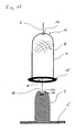
- FIGS. 1 and 2 Based on FIGS. 1 and 2 the basic procedure for the production of the split tube according to the invention is described. First, a prefabricated structure, which forms the outer layer 4 of the split tube according to the invention, is placed on an inner molded part 2.
- the inner mold part 2 is attached to a base plate 6 and has an outer shape which corresponds to the inner shape of the split tube to be formed.
- the outer layer 4 is pot-shaped or hood-shaped essentially prefabricated in the form of the can to be produced.
- the outer layer consists of a braid or fabric of fibers 8, in particular continuous, d. h, very long fibers 8.
- the outer layer is formed open at its one longitudinal end 10 in the direction of the gap tube or pump longitudinal axis Z. This longitudinal end is the open longitudinal end of the can to be manufactured.
- the outer material layer as well as the canned tube to be produced is designed to be closed.
- a curved bottom is provided which closes the otherwise substantially circular cylindrical outer layer 4 at the end 12.
- an opening 14 is formed, which extends from the outside into the interior of the outer layer 4.
- a collar 16 is formed on the outer periphery of the outer layer 4, which extends radially outwards and, when the outer layer 4 is placed on the inner mold part 2, comes to rest on the base plate 6.
- the outer layer 4, as in FIG. 1 is shown, is elastically stretchable, in particular in the radial or circumferential direction with respect to the longitudinal axis Z. As a result, a bias in the outer layer can be generated.
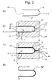
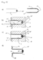
- FIGS. 2a to 2d show the stepwise process of casting the can.
- FIG. 2a shows First, the prefabricated outer layer 4 of an elastic, stretchable material, in particular a stretchable fabric. As based on FIG. 1 described, this outer layer 4 is first placed on the inner mold part 2 of an injection molding tool. Subsequently, the inner mold part 2 is assembled with an outer mold part 18.
- the outer mold part 18 of the injection molding tool has a recess 20 in the interior, which corresponds in its inner contour of the outer contour of the gap tube to be formed.
- the inner contour of the recess 20 is larger than the outer contour of the inner mold part 4, so that between the inner mold part 4 and the outer mold part 18, a gap 22 is formed, which corresponds in its dimension to the wall of the can to be formed. In this gap 22, the prefabricated outer layer 4 is inserted.
- the thickness of the outer layer 4 in the radial direction with respect to the longitudinal axis Z is less than the width of the gap 22.
- the outer layer 4 is initially not everywhere on the inner wall of the recess 20, but is spaced therefrom , This applies in particular to the cylindrical section of the can to be formed.
- the opening 14 on the closed side 12 of the outer layer 4 is opposite to an injection port 24 for injecting the plastic into the injection mold.
- the adjacent to the first longitudinal end 10 region of the outer layer 4 is not quite cylindrical, but widens by an angle ⁇ to the longitudinal end 10 out. This ensures that at the longitudinal end 10, the outer layer 4 is not applied to the outer wall of the inner mold part 2.
- the outer layer bears against the outer mold part 18 with a collar extending radially outwards, whereby it is possible to prevent the injected plastic from flowing around the outer layer 4 at this end and into the region of the gap 22 between the outer layer 4 and the inner wall of the recess 20 passes.
- the outer contour of the inner mold part 2 directly surrounding vent openings 26 are formed in the base plate 6, which are open to the gap 28 formed due to the angle ⁇ between the outer layer 2 and the outer wall of the inner mold part 2.
- the liquid plastic 30 is injected in the direction indicated by arrow 32 Fliescardi through the injection port 24 into the interior of the recess 20 of the outer mold 18.
- the liquid plastic 30 flows through the opening 14 in the outer layer 4 in the gap 28 between the outer layer 4 and the outer wall of the inner mold part 2.
- the outer layer 4 is stretched and pressed to the outside in that it comes to rest against the inside of the recess 20 of the outer molding 18.
- the gap 22 between the outer layer 4 and the outer surface of the inner mold part 2 is completely filled with plastic 30.
- the air previously present in this gap can escape through the vent openings 26.
- the outer layer 4 rests against the inner wall of the recess 20 on the circumference of the opening 14, so that penetration of the plastic 30 into the region between the inner wall of the recess 20 and the outer layer 4 is prevented.
- a gap 33 is provided, which is used to form a collar 34 on the split tube 36.
- the finished can which has been removed from the injection mold, is in Figure 2d shown.
- a pressure is preferably exerted on the base plate 6 in the direction of the outer molding or mold 18, whereby the gap 33 is reduced.
- the delayed solidification and increased shrinkage occurring due to the accumulation of material in the collar 34 can be compensated by moving the base plate 6.
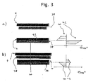
- FIG. 3a First, the situation is shown in which no stretching of the outer layer 4 takes place.
- the outer layer 4 and the inner layer 38 which is formed from the plastic 30, are shown separated from each other. It can be seen that the inner layer 38 has shrunk in reimbursement from the outer layer 4.
- the outer layer 4 and the inner layer 38 are firmly joined together, as in FIG. 3a
- the bonded outer layer 4 and the inner layer 38 tend to separate from each other or to delaminate.
- FIG. 3b now shows the embodiment according to the invention, according to which the outer layer 4 is elastically stretchable.
- the outer layer 4 is so stretchable that it can be stretched to a greater degree than the plastic 30 of the inner layer 38 shrinks during solidification.
- FIG. 3b Above are initially schematically the outer layer 4 and the inner layer 38 in not shown interconnected state.
- FIG. 3b below the two layers 4, 38 are shown in the connected state.
- the outer layer 4 is first stretched elastically. It is stretched more than the plastic shrinks 30 later in the solidification. Now, if the plastic 30 shrinks and solidifies, this leads to the outer layer 4 retains a certain bias.
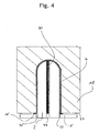
- FIG. 4 shows an injection molding tool with an inner mold part 2 and an outer mold part 18 as shown in FIG Figure 2c with injected plastic 30.
- the plastic 30 is not injected through an opening 14 in the outer layer 4 into the gap 22, but is introduced into the gap 22 through a channel 44 which extends longitudinally through the inner mold part 2.
- the channel 44 extends, starting from the base plate 6 facing the longitudinal end of the inner mold part 2 to the opposite end of the molding 2, which forms the bottom of the can.
- the plastic 30 is thus initially introduced into this bottom region, as in the embodiment according to FIG Figure 2c the case is the case, with the difference that the plastic 30 is injected directly from the inside into the interior of the outer layer 4.
- An opening 14 in the outer layer 4 is therefore not provided in this embodiment.
- FIG. 5 shows a further embodiment of an injection molding tool with an outer mold part 18 and an inner mold part 2 similar to the views in FIG Figure 2c and FIG. 4 , Unlike the ones based on Figure 2c and FIG. 4 shown procedures for injecting the plastic 30 is in the embodiment according to FIG. 5 the plastic 30 is injected from the open end of the can-to-be-molded tube, ie, from the base plate 6 of the inner die 2 into the gap 22.
- injection openings 46 are formed in the base plate 6, which are connected to an annular gap 48 which is formed between the end face of the outer mold part 18 and the base plate 6 and extends normal to the gap 22 and forms a collar 34 on the split tube 36 ,
- the outer layer 4 is formed so as to be slightly shorter than the recess 20 in the outer mold part 18 in the direction of the longitudinal axis Z. That is, the bottom of the outer layer 4 at the first longitudinal end 12 is not in the starting position at the bottom of the recess 20 but is spaced therefrom.
- the outer layer 4 is stretched not only in the radial direction R but also in the axial direction A.
- FIG. 6 shows a section of a section through the inner layer 38 of the can 36, which was formed in the preceding manner.
- a plastic 30 with fibers 50 contained therein is used for reinforcement. These fibers 50 are oriented in the Spaltrohrwandung defined or oriented.
- the inner layer 38 has three layers, namely two edge zones 38a and 38b spaced apart from one another in the radial direction with respect to the longitudinal axis Z and a middle layer 38c arranged therebetween. In the edge zones 38a and 38b, the fibers 50 are aligned in the axial direction, ie parallel to the longitudinal axis Z.
- the fibers 50 are directed in the circumferential direction with respect to the longitudinal axis Z.
- a reinforcement of the material of the inner layer 38 is achieved especially in the circumferential direction. In this direction, the largest loads occur when the interior of the can 36 is pressurized.
- the middle layer 38c makes in the radial direction with respect to the longitudinal axis Z preferably more than 40%, more preferably more than 60% of the wall thickness of the inner layer 38 from.
- FIG. 6 Orientation of the fibers 50 shown is achieved in that during the injection of the plastic 30 into the gap 28 between the outer layer 4 and the outer wall of the inner mold part 2, the inner mold part 2 relative to the outer mold 18 and the outer layer 4 arranged therein is rotated about the longitudinal axis Z. This leads to the circumferential orientation of the fibers 50 in the middle layer 38 c.
- the fibers 50 in the edge zones 38a and 38b are directed in the flow direction of the plastic 30 during injection into the gap. Since, as previously with reference to Figure 2c .
- FIG. 4 and FIG. 5 described the flow direction in the axial direction, ie parallel to the longitudinal axis Z is in the edge zones, the alignment of the fibers 50 in this direction respectively.
- the rotation of the inner mold part 2 relative to the outer mold 18 can in principle be carried out in all the embodiments described above.
- a central fixed region of the inner mold part 2 can be formed, through which the plastic is supplied.
- a rotatable outer part of the inner mold part 2 can be arranged concentrically around this fixed area, which outer outer surface faces the outer mold part 18 and defines the mold gap.
- an additional annular gap 49 may be provided which separates the base plate 6 from the inner mold part 2 so that the inner mold part 2 can be rotated relative to the base plate 6 and the outer mold part 18.
- the base plate 6 also be firmly connected to the inner mold part 2.
- FIGS. 7a, 7b and 8a to 8c Below is the production of the inner layer 4, as it is inserted into the gap 22 between the outer mold part 18 and inner mold part 2 described.
- a section 54 is cut from a long fabric tube 52, as in FIG Figure 7a is shown. This section is then twisted in the middle about its longitudinal axis and then turned inside out, so that a two-layered cup-shaped structure is created, as in FIG. 7b is shown.
- This fabric structure 56 is slipped over a core 58, which has the outer shape, which corresponds to the inner contour of the fabric layer to be formed. Subsequently, this arrangement of the fabric structure 56 on the core 58, as in FIG. 7d shown heated by a heater 59.
- FIG. 8a the tissue structure 56 on the core 58, which is arranged on a base plate 61.
- a mold 60 which has a recess in its interior, which corresponds to the outer contour of the outer layer to be produced 4, placed over the arrangement of the core 58 and fabric structure 56 and so pressed the fabric structure 56 between the core 58 and mold 60 in shape , as in FIG. 8b shown.
- the fabric structure 56, the outer layer 4, which in FIG. 8c is shown.
- a cooling device for cooling the layer 4 is arranged in the mold 60.
- the outer layer 4 takes its shape by heating and compressing a fabric structure 56 of a plastic fabric or plastic fibers, which facilitates insertion into the injection mold. In this case, the outer layer 4 then has the desired defined elastic extensibility. Alternatively or additionally, it is possible to impregnate or impregnate the fabric structure 56 with further plastic material.
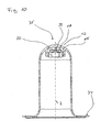
- FIG. 9 shows in a sectional view an example of an inventively designed canned tube 36.
- the outer layer 4 and the inner layer 38 are not shown individually.
- the wall of the can 36 is shown as a homogeneous material.
- two sections 62, 64 are provided in the direction of the longitudinal axis Z, in which the split tube has different wall thicknesses.
- both the diameter of the split tube 36 and the wall thickness is greater than in the section 64. This is achieved in that the gap 22, between the inner mold part 2 and outer mold part 18 is formed correspondingly different widths.
- FIG. 10 shows a sectional view of another embodiment of the split tube 36 according to the invention, also here the wall is simplified without distinction of the inner layer 38 and the outer layer 4 shown.
- Essential in the embodiment according to FIG. 10 is that in the split tube 36, ie in the inner layer 38 at the closed axial end 12, a bearing holder 66 is cast. In the bearing holder 66, a bearing 68 is arranged. The bearing 68 serves to support the rotor shaft of the rotor to be arranged in the can 36. Between the bearing 68 and the bearing holder 66, a free space 70 is formed.
- flow paths 72 are provided, which extend in the axial direction on the circumference of the bearing 68 between the latter and the bearing holder 66. These flow paths 72 and the free space 70 serve to ensure that the fluid in the interior of the can 36 also reaches the bearing and can flow around the bearing.
- FIGS. 1 and 2 will explain how a bearing holder 66 can be poured into the can 36. It should be understood that instead of the bearing holder 66 also directly a bearing 68 could be poured, which would be done accordingly.
- the bearing holder 66 and the bearing 68 is shown only schematically. It should be understood that these elements may be formed as shown in the other figures.
- FIG. 11 It can be seen that on the inner mold part 2 of the injection molding tool at the free end end, which faces the first longitudinal end 12 of the can or the outer layer 4, an end-side recess 74 is formed, in which the bearing holder 66 is inserted.
- means not shown here are provided in the recess 74 to center the bearing holder 66 exactly with respect to the longitudinal axis Z and to fix in a defined position to the inner mold part 2.
- the circumferential inner wall of the recess 74 remains an annular gap 76.
- the bearing 68 and the bearing holder 66 may at its the gap 76 facing surface in be suitably structured so that the plastic 30 can later engage in this structure and can cause a firm connection between the bearing holder 68 and the inner layer 38 in both the circumferential and in the axial direction with respect to the longitudinal axis Z.
- the insertion of the inner layer 4 between the outer mold part 8 and the inner mold part 2 also takes place in the embodiment according to Figures 11 and 12 in the basis of the FIGS. 1 and 2 explained way. That is, after inserting the bearing holder 66 in the inner mold part 2, the outer, prefabricated layer is placed over this inner mold part 2. Subsequently, as in the Figures 12b and 12c is shown, as explained FIGS. 2b and 2c the injection of the plastic 30.
- FIG. 2 directed.
- the plastic 30 flows while, as in FIG. 12c is shown, also in the annular gap 76 and flows around the bearing holder 66. In this case, the plastic with corresponding structuring on the surface of the bearing holder 66 engages. As in FIG. 12d is shown, then the bearing holder 66 is firmly molded into the plastic material of the inner layer 38 and thus fixed in the can 36.
- FIG. 12d It can also be seen that the collar 34 is formed longer in the radial direction than the collar of the outer layer 4. In this way, a flange or collar part 78 is formed, which is molded only from the plastic of the inner layer by injection molding. That is, the radially outer collar portion 78 is not reinforced by the outer layer 4.
- plastic 30 for the inner layer 38 a homogeneous plastic material or a plastic composite material can be used in all the embodiments described above.
- a plastic composite material may contain, in addition to the plastic components of other plastics or materials.
- individual fibers may be added for reinforcement. These can then be oriented in the manner described above in the can.
Landscapes
- Engineering & Computer Science (AREA)
- Power Engineering (AREA)
- Mechanical Engineering (AREA)
- Manufacturing & Machinery (AREA)
- General Engineering & Computer Science (AREA)
- Injection Moulding Of Plastics Or The Like (AREA)
- Structures Of Non-Positive Displacement Pumps (AREA)
Claims (19)
- Gaine d'un moteur d'entraînement pour un groupe motopompe, la gaine (36) étant réalisée au moins partiellement en matière plastique, caractérisée en ce que la gaine (36) présente une couche extérieure (4) en matériau élastiquement précontraint et une couche intérieure (38) constituée d'une matière plastique injectée (30) contenant des fibres (50) de renforcement, la couche extérieure (4) étant extensible élastiquement d'une valeur supérieure au degré de retrait de la matière plastique injectée (30) lors de sa solidification et la couche extérieure (4) opérant, par sa précontrainte, une contrainte de compression agissant de l'extérieur sur la couche intérieure.
- Gaine selon la revendication 1, caractérisée en ce que le matériau précontraint (4) contient un matériau fibreux et, en particulier, un tissu qui est noyé, de préférence, dans une matière plastique.
- Gaine selon l'une des revendications précédentes, caractérisée en ce que la couche extérieure (4) présente au moins une ouverture (14) à travers laquelle la matière plastique est injectée depuis la face externe de la couche extérieure (4) jusqu'à l'intérieur de celle-ci.
- Gaine selon l'une des revendications précédentes, caractérisée en ce que la matière plastique contient un thermoplastique.
- Gaine selon l'une des revendications précédentes, caractérisée en ce que les fibres (50) de renforcement contenues dans la matière plastique sont orientées de manière définie.
- Gaine selon l'une des revendications précédentes, caractérisée en ce que la couche intérieure (38) présente plusieurs strates (38a, 38b, 38c) dans lesquelles des fibres (50) présentes dans la matière plastique ont une orientation définie de manière différente.
- Gaine selon l'une des revendications précédentes, caractérisée en ce que le matériau précontraint (4) comprend des fibres thermoplastiques, fibres de carbone, fibres de verre, fibres métalliques et/ou fibres d'aramide.
- Gaine selon l'une des revendications précédentes, caractérisée en ce qu'un palier (68) ou un support de palier (66) est noyé dans la matière plastique (30) de la couche intérieure (38).
- Procédé de fabrication d'une gaine d'un moteur d'entraînement pour un groupe motopompe, dans lequel la gaine (36) est réalisée au moins partiellement en matière plastique, caractérisé par les étapes suivantes :insertion d'une couche extérieure (4) en matériau extensible élastiquement dans un outil de moulage par injection comportant au moins une partie de moule intérieure (2) et une partie de moule extérieure (18),introduction de matière plastique liquide dans un espace libre (22, 28) entre le moule intérieur (2) et le moule extérieur (18) de telle façon que la matière plastique (30) soit introduite entre le moule intérieur (2) et la couche extérieure (4), le matériau extensible (4) étant étiré d'une valeur supérieure au degré de retrait de la matière plastique (30) introduite lors de sa solidification, etsolidification de la matière plastique dans l'outil de moulage par injection.
- Procédé selon la revendication 9, caractérisé en ce que le matériau extensible (4) est un matériau fibreux et, en particulier, un tissu.
- Procédé selon l'une des revendications 9 à 10, caractérisé en ce que, pendant l'introduction et/ou la solidification de la matière plastique (30), on fait tourner le moule intérieur (2) par rapport au moule extérieur (18) et/ou par rapport à la couche extérieure (4) autour de l'axe longitudinal (Z) de la gaine (36) à former.
- Procédé selon l'une des revendications 9 à 11, caractérisé en ce que la matière plastique (30) entre le moule intérieur (2) et la couche extérieure (4) s'écoule, lors de l'injection, d'une manière sensiblement parallèle à l'axe longitudinal (Z) de la gaine (36) à former.
- Procédé selon l'une des revendications 9 à 12, caractérisé en ce que la matière plastique (30) est injectée à l'intérieur de la couche extérieure (4) à partir d'un côté frontal (12) axial fermé de la gaine (36) à former ou à partir d'un côté frontal (10) axial ouvert de la gaine (36) à former.
- Procédé selon l'une des revendications 9 à 13, caractérisé en ce que la matière plastique (30) est injectée à l'intérieur de la couche extérieure (4) à au moins une position située entre les deux extrémités axiales (10, 12) de la gaine à former.
- Procédé selon l'une des revendications 9 à 14, caractérisé en ce que la matière plastique (30) est introduite à l'intérieur de la couche extérieure (4) à travers une ouverture (14) réalisée dans la couche extérieure, qui est disposée, de préférence, à une position centrale dans le fond (12) de la gaine en forme de pot (36) à former.
- Procédé selon l'une des revendications 9 à 15, caractérisé en ce que des fibres de renforcement sont ajoutées à la matière plastique (30).
- Procédé selon l'une des revendications 9 à 16, caractérisé en ce qu'est donnée à la couche extérieure (4), avant insertion dans l'outil de moulage, une forme qui correspond sensiblement à la forme de la gaine (36) à former.
- Procédé selon l'une des revendications 9 à 17, caractérisé en ce qu'un palier (68) ou un support de palier (66) est inséré à une position prédéterminée dans l'outil de moulage par injection avant introduction de la matière plastique (30) liquide.
- Procédé selon l'une des revendications 10 à 18, caractérisé en ce que l'outil de moulage par injection présente un entrefer (33) configuré pour former une collerette (34) s'étendant radialement au niveau de l'extrémité ouverte de la gaine (36) à réaliser, une pression étant appliquée, pendant la solidification de la matière plastique (30), sur au moins l'une des parois de l'outil de moulage par injection définissant l'entrefer (33), pression dirigée vers la paroi opposée.
Priority Applications (3)
| Application Number | Priority Date | Filing Date | Title |
|---|---|---|---|
| EP07018589.7A EP2040352B2 (fr) | 2007-09-21 | 2007-09-21 | Gaine d'entrefer et son procédé de fabrication |
| AT07018589T ATE509417T1 (de) | 2007-09-21 | 2007-09-21 | Spaltrohr sowie verfahren zum herstellen eines spaltrohres |
| PCT/EP2008/006996 WO2009039932A1 (fr) | 2007-09-21 | 2008-08-27 | Gaine et procédé de fabrication de gaine |
Applications Claiming Priority (1)
| Application Number | Priority Date | Filing Date | Title |
|---|---|---|---|
| EP07018589.7A EP2040352B2 (fr) | 2007-09-21 | 2007-09-21 | Gaine d'entrefer et son procédé de fabrication |
Publications (3)
| Publication Number | Publication Date |
|---|---|
| EP2040352A1 EP2040352A1 (fr) | 2009-03-25 |
| EP2040352B1 EP2040352B1 (fr) | 2011-05-11 |
| EP2040352B2 true EP2040352B2 (fr) | 2014-11-19 |
Family
ID=39170057
Family Applications (1)
| Application Number | Title | Priority Date | Filing Date |
|---|---|---|---|
| EP07018589.7A Not-in-force EP2040352B2 (fr) | 2007-09-21 | 2007-09-21 | Gaine d'entrefer et son procédé de fabrication |
Country Status (3)
| Country | Link |
|---|---|
| EP (1) | EP2040352B2 (fr) |
| AT (1) | ATE509417T1 (fr) |
| WO (1) | WO2009039932A1 (fr) |
Families Citing this family (6)
| Publication number | Priority date | Publication date | Assignee | Title |
|---|---|---|---|---|
| EP2293417B1 (fr) * | 2009-09-05 | 2016-07-06 | Grundfos Management A/S | Pale de rotor |
| DE102010054577A1 (de) * | 2010-12-15 | 2012-06-21 | Wilo Se | Kunststoffspalttopf für Kreiselpumpen |
| GB2518208B (en) * | 2013-09-13 | 2016-06-01 | Yasa Motors Ltd | Stator-plate Overmoulding |
| GB2518209B (en) * | 2013-09-13 | 2016-08-03 | Yasa Motors Ltd | Pole-piece Bonding |
| DE102014202284A1 (de) * | 2014-02-07 | 2015-08-13 | Bühler Motor GmbH | Spaltrohrmotor für eine Ölpumpe |
| WO2022248598A1 (fr) * | 2021-05-27 | 2022-12-01 | KSB SE & Co. KGaA | Procédé de production d'un tube fendu ou d'une coupe à tube fendu pour une pompe à rotor humide, et pompe à rotor humide comprenant un tube fendu ou une coupe à tube fendu |
Citations (11)
| Publication number | Priority date | Publication date | Assignee | Title |
|---|---|---|---|---|
| JPS61189913A (ja) † | 1985-02-19 | 1986-08-23 | Riken Corp | 合成樹脂製の管継手製造法 |
| EP0290824A2 (fr) † | 1987-05-09 | 1988-11-17 | Franz Klaus Union Armaturen Pumpen GmbH & Co. | Actionnement magnétique pour pompes |
| EP0466947A1 (fr) † | 1988-08-25 | 1992-01-22 | PepsiCo, Inc. | Procédé pour mouler une structure à couche multiple et récipient obtenu |
| DE4404235C1 (de) † | 1994-02-10 | 1995-01-05 | Urenco Deutschland Gmbh | Verfahren zum Herstellen eines Spalttopfes aus Faserverbundwerkstoff |
| EP0268085B1 (fr) † | 1986-10-25 | 1995-01-25 | Richter Chemie-Technik GmbH | Pompe de circulation magnétique |
| DE19747021A1 (de) † | 1997-10-24 | 1999-04-29 | Ver Foerderung Inst Kunststoff | Verfahren zum Spritzgießen endlosfaserverstärkter Hohlkörper |
| DE19912614A1 (de) † | 1999-03-22 | 2000-09-28 | Wilo Gmbh | Spalttopf für Kreiselpumpe |
| EP1059722B1 (fr) † | 1999-06-10 | 2002-09-18 | WILO GmbH | Manchon d'entrefer en matière plastique renforcée de fibres |
| EP1584452A2 (fr) † | 2004-04-08 | 2005-10-12 | Grundfos a/s | Procédé pour le formage d'un élément creux de forme stable pourvu d'un fond et utilisation d'un tel élément |
| EP1649999A2 (fr) † | 2004-10-21 | 2006-04-26 | Christian Fuchs | Procédé pour produire un objet structurellement stable avec une structure textile plane, en particulier avec une surface de recouvrement en structure composite renforcée par des fibres |
| EP1703135A2 (fr) † | 2005-02-25 | 2006-09-20 | Wilo Ag | Chemise d'entrefer pour une motopompe centrifuge |
Family Cites Families (3)
| Publication number | Priority date | Publication date | Assignee | Title |
|---|---|---|---|---|
| DE4342649C1 (de) * | 1993-12-14 | 1995-02-16 | Munsch Kunststoff Schweistechn | Magnetkreiselpumpe für aggressive Medien |
| EP0934809A1 (fr) * | 1998-02-05 | 1999-08-11 | H. Weidmann AG | Bouclier thermique pour un véhicule automobile |
| DE102005039124B4 (de) * | 2005-08-15 | 2009-11-26 | Faurecia Innenraum Systeme Gmbh | Verfahren zur Herstellung eines zweischichtigen Verbundteils |
-
2007
- 2007-09-21 EP EP07018589.7A patent/EP2040352B2/fr not_active Not-in-force
- 2007-09-21 AT AT07018589T patent/ATE509417T1/de active
-
2008
- 2008-08-27 WO PCT/EP2008/006996 patent/WO2009039932A1/fr not_active Ceased
Patent Citations (11)
| Publication number | Priority date | Publication date | Assignee | Title |
|---|---|---|---|---|
| JPS61189913A (ja) † | 1985-02-19 | 1986-08-23 | Riken Corp | 合成樹脂製の管継手製造法 |
| EP0268085B1 (fr) † | 1986-10-25 | 1995-01-25 | Richter Chemie-Technik GmbH | Pompe de circulation magnétique |
| EP0290824A2 (fr) † | 1987-05-09 | 1988-11-17 | Franz Klaus Union Armaturen Pumpen GmbH & Co. | Actionnement magnétique pour pompes |
| EP0466947A1 (fr) † | 1988-08-25 | 1992-01-22 | PepsiCo, Inc. | Procédé pour mouler une structure à couche multiple et récipient obtenu |
| DE4404235C1 (de) † | 1994-02-10 | 1995-01-05 | Urenco Deutschland Gmbh | Verfahren zum Herstellen eines Spalttopfes aus Faserverbundwerkstoff |
| DE19747021A1 (de) † | 1997-10-24 | 1999-04-29 | Ver Foerderung Inst Kunststoff | Verfahren zum Spritzgießen endlosfaserverstärkter Hohlkörper |
| DE19912614A1 (de) † | 1999-03-22 | 2000-09-28 | Wilo Gmbh | Spalttopf für Kreiselpumpe |
| EP1059722B1 (fr) † | 1999-06-10 | 2002-09-18 | WILO GmbH | Manchon d'entrefer en matière plastique renforcée de fibres |
| EP1584452A2 (fr) † | 2004-04-08 | 2005-10-12 | Grundfos a/s | Procédé pour le formage d'un élément creux de forme stable pourvu d'un fond et utilisation d'un tel élément |
| EP1649999A2 (fr) † | 2004-10-21 | 2006-04-26 | Christian Fuchs | Procédé pour produire un objet structurellement stable avec une structure textile plane, en particulier avec une surface de recouvrement en structure composite renforcée par des fibres |
| EP1703135A2 (fr) † | 2005-02-25 | 2006-09-20 | Wilo Ag | Chemise d'entrefer pour une motopompe centrifuge |
Non-Patent Citations (3)
| Title |
|---|
| A. MEDDAD ET AL.: "Weldline Strength in Glass Fiber Reinforced Polyamide 66", POLYMER ENGINEERING AND SCIENCE, vol. 35, no. 11, 1995, pages 893 - 901 † |
| DR.-ING. F. JOHANNABER ET AL.: "Handbuch Spritzgießen", vol. 2, 2004, CARL HANSER VERLAG, MÜNCHEN, pages: 386 - 389 † |
| M. WALTER ET AL.: "Endlosverstärkte Teile durch Umspritzen", PLASVERARBEITER, vol. 49, no. 1, January 1998 (1998-01-01), pages 37 - 39 † |
Also Published As
| Publication number | Publication date |
|---|---|
| EP2040352B1 (fr) | 2011-05-11 |
| EP2040352A1 (fr) | 2009-03-25 |
| WO2009039932A1 (fr) | 2009-04-02 |
| ATE509417T1 (de) | 2011-05-15 |
Similar Documents
| Publication | Publication Date | Title |
|---|---|---|
| EP2040354B2 (fr) | Gaine d'un moteur de commande pour un agrégat de pompe | |
| EP1777439B1 (fr) | Procédé de fabrication d'une roue dentée | |
| DE69632358T2 (de) | Herstellung von grossen Verbundstrukturen | |
| DE69415715T2 (de) | Verfahren und Vorrichtung zum Herstellen von Isolatoren | |
| DE102011078951B4 (de) | Verfahren zum Herstellen eines Rotorblatts für eine Windenergieanlage, Sandwich-Preform und Rotorblatt für eine Windenergieanlage | |
| EP2040352B2 (fr) | Gaine d'entrefer et son procédé de fabrication | |
| EP2666615B1 (fr) | Procédé de fabrication d'une demi-coque pour pale de rotor d'éolienne ou d'une pale de rotor d'éolienne et moule de fabrication à cette fin | |
| EP3018342B2 (fr) | Procede de fabrication d'une pale de rotor d'eolienne | |
| EP1916091A1 (fr) | Procédé de fabrication d'éléments composites en fibre | |
| DE102014107584A1 (de) | Vorrichtung und Verfahren zur Herstellung von Faserverbundbauteilen sowie Faserverbundbauteil | |
| DE4120133C2 (de) | Bauteil und Verfahren zur Herstellung eines solchen | |
| DE102014206870A1 (de) | Lageranordnung und Verfahren zu ihrer Herstellung | |
| EP1527867A1 (fr) | Procédé de fabrication d'une roue ventilateur et roue ventilateur selon ce procédé | |
| DE102011009506B4 (de) | Vorrichtung zur Herstellung hohler Formbauteile aus einem Faserverbundwerkstoff | |
| DE102021103943A1 (de) | Verfahren zum Herstellen eines faserverstärkten Harzformartikels und Herstellungsvorrichtung desselben | |
| DE102012210469A1 (de) | Rad aus Faserverbundwerkstoff und Verfahren zu seiner Herstellung | |
| DE102012013538B4 (de) | Verfahren zur Herstellung von Sandwichelementen | |
| DE102008029518A1 (de) | Verfahren zur Herstellung von Faserverbundbauteilen und Faserverbundbauteile | |
| EP3521631B1 (fr) | Roue mobile de pompage, procédé de fabrication d'une roue mobile de pompage et pompe dotée de la roue mobile de pompage | |
| DE2359216A1 (de) | Treibriemen und verfahren zur herstellung eines derartigen treibriemens | |
| EP1584452B1 (fr) | Procédé pour le formage d'un élément creux de forme stable pourvu d'un fond et utilisation d'un tel élément | |
| DE102007061526A1 (de) | Kunststoff-Laugenbehälter für eine Waschmaschine oder einen Waschtrockner und Verfahren zur Herstellung des Laugenbehälters | |
| DE102017222615A1 (de) | Rotor sowie Verfahren zum Herstellen eines Rotors | |
| DE102014017809B4 (de) | Verfahren zur Herstellung eines Strukturbauteils | |
| DE102015119401A1 (de) | Verfahren zur Herstellung eines Sandwichbauteils |
Legal Events
| Date | Code | Title | Description |
|---|---|---|---|
| PUAI | Public reference made under article 153(3) epc to a published international application that has entered the european phase |
Free format text: ORIGINAL CODE: 0009012 |
|
| AK | Designated contracting states |
Kind code of ref document: A1 Designated state(s): AT BE BG CH CY CZ DE DK EE ES FI FR GB GR HU IE IS IT LI LT LU LV MC MT NL PL PT RO SE SI SK TR |
|
| AX | Request for extension of the european patent |
Extension state: AL BA HR MK RS |
|
| 17P | Request for examination filed |
Effective date: 20090310 |
|
| AKX | Designation fees paid |
Designated state(s): AT BE BG CH CY CZ DE DK EE ES FI FR GB GR HU IE IS IT LI LT LU LV MC MT NL PL PT RO SE SI SK TR |
|
| GRAP | Despatch of communication of intention to grant a patent |
Free format text: ORIGINAL CODE: EPIDOSNIGR1 |
|
| GRAS | Grant fee paid |
Free format text: ORIGINAL CODE: EPIDOSNIGR3 |
|
| GRAA | (expected) grant |
Free format text: ORIGINAL CODE: 0009210 |
|
| AK | Designated contracting states |
Kind code of ref document: B1 Designated state(s): AT BE BG CH CY CZ DE DK EE ES FI FR GB GR HU IE IS IT LI LT LU LV MC MT NL PL PT RO SE SI SK TR |
|
| REG | Reference to a national code |
Ref country code: GB Ref legal event code: FG4D Free format text: NOT ENGLISH |
|
| REG | Reference to a national code |
Ref country code: CH Ref legal event code: EP |
|
| REG | Reference to a national code |
Ref country code: IE Ref legal event code: FG4D |
|
| REG | Reference to a national code |
Ref country code: DE Ref legal event code: R096 Ref document number: 502007007187 Country of ref document: DE Effective date: 20110622 |
|
| REG | Reference to a national code |
Ref country code: NL Ref legal event code: VDEP Effective date: 20110511 |
|
| PG25 | Lapsed in a contracting state [announced via postgrant information from national office to epo] |
Ref country code: LT Free format text: LAPSE BECAUSE OF FAILURE TO SUBMIT A TRANSLATION OF THE DESCRIPTION OR TO PAY THE FEE WITHIN THE PRESCRIBED TIME-LIMIT Effective date: 20110511 Ref country code: SE Free format text: LAPSE BECAUSE OF FAILURE TO SUBMIT A TRANSLATION OF THE DESCRIPTION OR TO PAY THE FEE WITHIN THE PRESCRIBED TIME-LIMIT Effective date: 20110511 Ref country code: PT Free format text: LAPSE BECAUSE OF FAILURE TO SUBMIT A TRANSLATION OF THE DESCRIPTION OR TO PAY THE FEE WITHIN THE PRESCRIBED TIME-LIMIT Effective date: 20110912 |
|
| PG25 | Lapsed in a contracting state [announced via postgrant information from national office to epo] |
Ref country code: FI Free format text: LAPSE BECAUSE OF FAILURE TO SUBMIT A TRANSLATION OF THE DESCRIPTION OR TO PAY THE FEE WITHIN THE PRESCRIBED TIME-LIMIT Effective date: 20110511 Ref country code: CY Free format text: LAPSE BECAUSE OF FAILURE TO SUBMIT A TRANSLATION OF THE DESCRIPTION OR TO PAY THE FEE WITHIN THE PRESCRIBED TIME-LIMIT Effective date: 20110511 Ref country code: LV Free format text: LAPSE BECAUSE OF FAILURE TO SUBMIT A TRANSLATION OF THE DESCRIPTION OR TO PAY THE FEE WITHIN THE PRESCRIBED TIME-LIMIT Effective date: 20110511 Ref country code: IS Free format text: LAPSE BECAUSE OF FAILURE TO SUBMIT A TRANSLATION OF THE DESCRIPTION OR TO PAY THE FEE WITHIN THE PRESCRIBED TIME-LIMIT Effective date: 20110911 Ref country code: SI Free format text: LAPSE BECAUSE OF FAILURE TO SUBMIT A TRANSLATION OF THE DESCRIPTION OR TO PAY THE FEE WITHIN THE PRESCRIBED TIME-LIMIT Effective date: 20110511 Ref country code: GR Free format text: LAPSE BECAUSE OF FAILURE TO SUBMIT A TRANSLATION OF THE DESCRIPTION OR TO PAY THE FEE WITHIN THE PRESCRIBED TIME-LIMIT Effective date: 20110812 Ref country code: ES Free format text: LAPSE BECAUSE OF FAILURE TO SUBMIT A TRANSLATION OF THE DESCRIPTION OR TO PAY THE FEE WITHIN THE PRESCRIBED TIME-LIMIT Effective date: 20110822 |
|
| REG | Reference to a national code |
Ref country code: IE Ref legal event code: FD4D |
|
| PG25 | Lapsed in a contracting state [announced via postgrant information from national office to epo] |
Ref country code: NL Free format text: LAPSE BECAUSE OF FAILURE TO SUBMIT A TRANSLATION OF THE DESCRIPTION OR TO PAY THE FEE WITHIN THE PRESCRIBED TIME-LIMIT Effective date: 20110511 |
|
| PG25 | Lapsed in a contracting state [announced via postgrant information from national office to epo] |
Ref country code: EE Free format text: LAPSE BECAUSE OF FAILURE TO SUBMIT A TRANSLATION OF THE DESCRIPTION OR TO PAY THE FEE WITHIN THE PRESCRIBED TIME-LIMIT Effective date: 20110511 Ref country code: IE Free format text: LAPSE BECAUSE OF FAILURE TO SUBMIT A TRANSLATION OF THE DESCRIPTION OR TO PAY THE FEE WITHIN THE PRESCRIBED TIME-LIMIT Effective date: 20110511 Ref country code: CZ Free format text: LAPSE BECAUSE OF FAILURE TO SUBMIT A TRANSLATION OF THE DESCRIPTION OR TO PAY THE FEE WITHIN THE PRESCRIBED TIME-LIMIT Effective date: 20110511 |
|
| PLBI | Opposition filed |
Free format text: ORIGINAL CODE: 0009260 |
|
| PG25 | Lapsed in a contracting state [announced via postgrant information from national office to epo] |
Ref country code: DK Free format text: LAPSE BECAUSE OF FAILURE TO SUBMIT A TRANSLATION OF THE DESCRIPTION OR TO PAY THE FEE WITHIN THE PRESCRIBED TIME-LIMIT Effective date: 20110511 Ref country code: RO Free format text: LAPSE BECAUSE OF FAILURE TO SUBMIT A TRANSLATION OF THE DESCRIPTION OR TO PAY THE FEE WITHIN THE PRESCRIBED TIME-LIMIT Effective date: 20110511 Ref country code: SK Free format text: LAPSE BECAUSE OF FAILURE TO SUBMIT A TRANSLATION OF THE DESCRIPTION OR TO PAY THE FEE WITHIN THE PRESCRIBED TIME-LIMIT Effective date: 20110511 Ref country code: PL Free format text: LAPSE BECAUSE OF FAILURE TO SUBMIT A TRANSLATION OF THE DESCRIPTION OR TO PAY THE FEE WITHIN THE PRESCRIBED TIME-LIMIT Effective date: 20110511 |
|
| PLAX | Notice of opposition and request to file observation + time limit sent |
Free format text: ORIGINAL CODE: EPIDOSNOBS2 |
|
| 26 | Opposition filed |
Opponent name: WILO SE Effective date: 20120211 |
|
| BERE | Be: lapsed |
Owner name: GRUNDFOS MANAGEMENT A/S Effective date: 20110930 |
|
| PG25 | Lapsed in a contracting state [announced via postgrant information from national office to epo] |
Ref country code: MC Free format text: LAPSE BECAUSE OF NON-PAYMENT OF DUE FEES Effective date: 20110930 |
|
| REG | Reference to a national code |
Ref country code: CH Ref legal event code: PL |
|
| REG | Reference to a national code |
Ref country code: DE Ref legal event code: R026 Ref document number: 502007007187 Country of ref document: DE Effective date: 20120211 |
|
| PG25 | Lapsed in a contracting state [announced via postgrant information from national office to epo] |
Ref country code: BE Free format text: LAPSE BECAUSE OF NON-PAYMENT OF DUE FEES Effective date: 20110930 |
|
| PLBB | Reply of patent proprietor to notice(s) of opposition received |
Free format text: ORIGINAL CODE: EPIDOSNOBS3 |
|
| PG25 | Lapsed in a contracting state [announced via postgrant information from national office to epo] |
Ref country code: CH Free format text: LAPSE BECAUSE OF NON-PAYMENT OF DUE FEES Effective date: 20110930 Ref country code: LI Free format text: LAPSE BECAUSE OF NON-PAYMENT OF DUE FEES Effective date: 20110930 |
|
| PG25 | Lapsed in a contracting state [announced via postgrant information from national office to epo] |
Ref country code: MT Free format text: LAPSE BECAUSE OF FAILURE TO SUBMIT A TRANSLATION OF THE DESCRIPTION OR TO PAY THE FEE WITHIN THE PRESCRIBED TIME-LIMIT Effective date: 20110511 |
|
| PG25 | Lapsed in a contracting state [announced via postgrant information from national office to epo] |
Ref country code: LU Free format text: LAPSE BECAUSE OF NON-PAYMENT OF DUE FEES Effective date: 20110921 |
|
| PG25 | Lapsed in a contracting state [announced via postgrant information from national office to epo] |
Ref country code: BG Free format text: LAPSE BECAUSE OF FAILURE TO SUBMIT A TRANSLATION OF THE DESCRIPTION OR TO PAY THE FEE WITHIN THE PRESCRIBED TIME-LIMIT Effective date: 20110811 |
|
| PG25 | Lapsed in a contracting state [announced via postgrant information from national office to epo] |
Ref country code: TR Free format text: LAPSE BECAUSE OF FAILURE TO SUBMIT A TRANSLATION OF THE DESCRIPTION OR TO PAY THE FEE WITHIN THE PRESCRIBED TIME-LIMIT Effective date: 20110511 |
|
| PG25 | Lapsed in a contracting state [announced via postgrant information from national office to epo] |
Ref country code: HU Free format text: LAPSE BECAUSE OF FAILURE TO SUBMIT A TRANSLATION OF THE DESCRIPTION OR TO PAY THE FEE WITHIN THE PRESCRIBED TIME-LIMIT Effective date: 20110511 |
|
| REG | Reference to a national code |
Ref country code: AT Ref legal event code: MM01 Ref document number: 509417 Country of ref document: AT Kind code of ref document: T Effective date: 20120921 |
|
| PG25 | Lapsed in a contracting state [announced via postgrant information from national office to epo] |
Ref country code: AT Free format text: LAPSE BECAUSE OF NON-PAYMENT OF DUE FEES Effective date: 20120921 |
|
| PUAH | Patent maintained in amended form |
Free format text: ORIGINAL CODE: 0009272 |
|
| STAA | Information on the status of an ep patent application or granted ep patent |
Free format text: STATUS: PATENT MAINTAINED AS AMENDED |
|
| 27A | Patent maintained in amended form |
Effective date: 20141119 |
|
| AK | Designated contracting states |
Kind code of ref document: B2 Designated state(s): AT BE BG CH CY CZ DE DK EE ES FI FR GB GR HU IE IS IT LI LT LU LV MC MT NL PL PT RO SE SI SK TR |
|
| REG | Reference to a national code |
Ref country code: DE Ref legal event code: R102 Ref document number: 502007007187 Country of ref document: DE |
|
| REG | Reference to a national code |
Ref country code: DE Ref legal event code: R102 Ref document number: 502007007187 Country of ref document: DE Effective date: 20141119 |
|
| PG25 | Lapsed in a contracting state [announced via postgrant information from national office to epo] |
Ref country code: LV Free format text: LAPSE BECAUSE OF FAILURE TO SUBMIT A TRANSLATION OF THE DESCRIPTION OR TO PAY THE FEE WITHIN THE PRESCRIBED TIME-LIMIT Effective date: 20141119 |
|
| REG | Reference to a national code |
Ref country code: FR Ref legal event code: PLFP Year of fee payment: 10 |
|
| REG | Reference to a national code |
Ref country code: FR Ref legal event code: PLFP Year of fee payment: 11 |
|
| REG | Reference to a national code |
Ref country code: FR Ref legal event code: PLFP Year of fee payment: 12 |
|
| PGFP | Annual fee paid to national office [announced via postgrant information from national office to epo] |
Ref country code: IT Payment date: 20210930 Year of fee payment: 15 Ref country code: FR Payment date: 20210927 Year of fee payment: 15 |
|
| PGFP | Annual fee paid to national office [announced via postgrant information from national office to epo] |
Ref country code: DE Payment date: 20210923 Year of fee payment: 15 Ref country code: GB Payment date: 20210923 Year of fee payment: 15 |
|
| REG | Reference to a national code |
Ref country code: DE Ref legal event code: R119 Ref document number: 502007007187 Country of ref document: DE |
|
| GBPC | Gb: european patent ceased through non-payment of renewal fee |
Effective date: 20220921 |
|
| PG25 | Lapsed in a contracting state [announced via postgrant information from national office to epo] |
Ref country code: FR Free format text: LAPSE BECAUSE OF NON-PAYMENT OF DUE FEES Effective date: 20220930 Ref country code: DE Free format text: LAPSE BECAUSE OF NON-PAYMENT OF DUE FEES Effective date: 20230401 |
|
| PG25 | Lapsed in a contracting state [announced via postgrant information from national office to epo] |
Ref country code: IT Free format text: LAPSE BECAUSE OF NON-PAYMENT OF DUE FEES Effective date: 20220921 Ref country code: GB Free format text: LAPSE BECAUSE OF NON-PAYMENT OF DUE FEES Effective date: 20220921 |