EP2040361A1 - Dispositif d'alimentation - Google Patents
Dispositif d'alimentation Download PDFInfo
- Publication number
- EP2040361A1 EP2040361A1 EP07767586A EP07767586A EP2040361A1 EP 2040361 A1 EP2040361 A1 EP 2040361A1 EP 07767586 A EP07767586 A EP 07767586A EP 07767586 A EP07767586 A EP 07767586A EP 2040361 A1 EP2040361 A1 EP 2040361A1
- Authority
- EP
- European Patent Office
- Prior art keywords
- voltage
- converter
- auxiliary device
- electricity storage
- storage device
- Prior art date
- Legal status (The legal status is an assumption and is not a legal conclusion. Google has not performed a legal analysis and makes no representation as to the accuracy of the status listed.)
- Withdrawn
Links
Images



Classifications
-
- H—ELECTRICITY
- H02—GENERATION; CONVERSION OR DISTRIBUTION OF ELECTRIC POWER
- H02J—ELECTRIC POWER NETWORKS; CIRCUIT ARRANGEMENTS OR SYSTEMS FOR SUPPLYING OR DISTRIBUTING ELECTRIC POWER; SYSTEMS FOR STORING ELECTRIC ENERGY
- H02J7/00—Circuit arrangements for charging or discharging batteries or for supplying loads from batteries
- H02J7/34—Parallel operation in networks using both storage and other DC sources, e.g. providing buffering
-
- H—ELECTRICITY
- H02—GENERATION; CONVERSION OR DISTRIBUTION OF ELECTRIC POWER
- H02J—ELECTRIC POWER NETWORKS; CIRCUIT ARRANGEMENTS OR SYSTEMS FOR SUPPLYING OR DISTRIBUTING ELECTRIC POWER; SYSTEMS FOR STORING ELECTRIC ENERGY
- H02J7/00—Circuit arrangements for charging or discharging batteries or for supplying loads from batteries
- H02J7/865—Battery or charger load switching, e.g. concurrent charging and load supply
-
- H—ELECTRICITY
- H02—GENERATION; CONVERSION OR DISTRIBUTION OF ELECTRIC POWER
- H02J—ELECTRIC POWER NETWORKS; CIRCUIT ARRANGEMENTS OR SYSTEMS FOR SUPPLYING OR DISTRIBUTING ELECTRIC POWER; SYSTEMS FOR STORING ELECTRIC ENERGY
- H02J2207/00—Details of circuit arrangements for charging or discharging batteries or supplying loads from batteries
- H02J2207/20—Charging or discharging characterised by the power electronics converter
-
- H—ELECTRICITY
- H02—GENERATION; CONVERSION OR DISTRIBUTION OF ELECTRIC POWER
- H02M—APPARATUS FOR CONVERSION BETWEEN AC AND AC, BETWEEN AC AND DC, OR BETWEEN DC AND DC, AND FOR USE WITH MAINS OR SIMILAR POWER SUPPLY SYSTEMS; CONVERSION OF DC OR AC INPUT POWER INTO SURGE OUTPUT POWER; CONTROL OR REGULATION THEREOF
- H02M1/00—Details of apparatus for conversion
- H02M1/0067—Converter structures employing plural converter units, other than for parallel operation of the units on a single load
- H02M1/007—Plural converter units in cascade
-
- H—ELECTRICITY
- H02—GENERATION; CONVERSION OR DISTRIBUTION OF ELECTRIC POWER
- H02M—APPARATUS FOR CONVERSION BETWEEN AC AND AC, BETWEEN AC AND DC, OR BETWEEN DC AND DC, AND FOR USE WITH MAINS OR SIMILAR POWER SUPPLY SYSTEMS; CONVERSION OF DC OR AC INPUT POWER INTO SURGE OUTPUT POWER; CONTROL OR REGULATION THEREOF
- H02M1/00—Details of apparatus for conversion
- H02M1/0083—Converters characterised by their input or output configuration
- H02M1/0093—Converters characterised by their input or output configuration wherein the output is created by adding a regulated voltage to or subtracting it from an unregulated input
Definitions
- the present invention relates to a power supply device that compensates for decrease in voltage of a DC voltage source.
- auxiliaries In other vehicles with no function of stop-idling, on-vehicle electric equipment as auxiliaries is making progress from hydraulic control to electric control for increasing gas mileage. For example, vehicles having assist equipment, such as electric power steering and electric brake control, are becoming available.
- the electric-driven auxiliaries are generally actuated on an as-needed basis, which brings about a state of large-current load of a pulse shape. Like the starter, this can also be a cause of decreasing battery voltage.
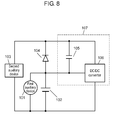
- FIG. 8 schematically shows the block diagram of the power supply device.
- First auxiliary device 101 is, for example, a starter that consumes instantaneous large current.
- DC voltage source 102 formed of a battery supplies first auxiliary device 101 with electric power.
- Second auxiliary device 103 is a device with a narrow permissible-range in input-voltage change, for example, an audio system, a navigation system, or an ECU (electronic control unit). Second auxiliary device 103 is fed from DC voltage source 102 via rectifier 104.
- Voltage compensation section 107 compensates for voltage drop when power is fed from DC voltage source 102 to second auxiliary device 103.
- Voltage compensation section 107 has energy storing source 105 and DC/DC converter 106.
- Energy storing source 105 is formed of an electricity storage device (for example, a capacitor) connected parallel with rectifier 104.
- DC voltage source 102 is the input source for DC/DC converter 106.
- Energy storing source 105 is connected to an output terminal of DC/DC converter 106.
- DC voltage source 102 maintains stability of voltage at around 12V since a large current does not flow into first auxiliary device 101. That is, electric power is fed with stability from DC voltage source 102 via rectifier 104 to second auxiliary device 103.
- a large current flows into first auxiliary device 101. This decreases output voltage of DC voltage source 102 to around 7V while first auxiliary device 101 is operating. The level of the voltage at this moment is far below a lower limit (e.g. 11V) of permissible range of voltage for second auxiliary device 103.
- voltage compensation section 107 starts to work. Specifically, when the voltage of DC voltage source 102 decreases below a predetermined value, DC/DC converter 106 starts charging operation on energy storing source 105 that has in-series connections with DC voltage source 102. As a result of the charging, the increase in voltage of energy storing source 105 compensates for the decrease in voltage of DC voltage source 102 and an increased amount of voltage is applied to second auxiliary device 103. The compensation allows second auxiliary device 103 to have stabilized voltage while first auxiliary device 101 is operating. The power supply device thus compensates for decrease in voltage of DC voltage source 102.
- the conventional power supply device has an improvement in that voltage compensation section 107 compensates for decrease in voltage of DC voltage source 102 so as to maintain stability of power supply to second auxiliary device 103.
- voltage compensation section 107 compensates for decrease in voltage of DC voltage source 102 so as to maintain stability of power supply to second auxiliary device 103.
- a large-capacity device i.e., energy storing source 105 here
- the current supply has to be provided from DC/DC converter 106 as a power supplier. That is, the rated current of DC/DC converter 106 has to be larger than the current consumed by second auxiliary device 103.
- the voltage of DC voltage source 102 decreases as a large current is flown into first auxiliary device 101 from DC voltage source 102.
- DC voltage source 102 supplies DC/DC converter 106 with current for stabilizing voltage of second auxiliary device 103. This causes a momentary increase in burden of electricity on DC voltage source 102.
- the voltage to be applied to first auxiliary device 101 including a starter has lost stability even though the voltage to be applied to second auxiliary device 103 can be stabilized.
- Patent document 1 Japanese Unexamined Patent Application Publication No. 2005-204421
- the power supply device of the present invention has a DC voltage source; a first auxiliary device connected parallel to the DC voltage source; a first rectifier connected to the DC voltage source; a second auxiliary device that receives electric power via the first rectifier; a first DC/DC converter that uses the DC voltage source as an input source; a large-capacity electricity storage device connected to an output terminal of the first DC/DC converter; and second DC/DC converter having an output terminal connected to the first rectifier, which uses the electricity storage device as an input source.
- the DC voltage source carries voltage higher than a predetermined value under the condition where the generator connected to the DC voltage source is in operation led by engine start-up. That is, in the condition of high voltage, the DC voltage source supplies the second auxiliary device with electric power via the first rectifier, and at the same time, first DC/DC converter puts the electricity storage device on charge with the use of the DC voltage source as an input source.
- second DC/DC converter uses the electricity storage device as an input source-that has been charged by the first DC/DC converter in advance-and then outputs voltage to both ends of the first rectifier for compensation of a decreased amount of battery voltage.
- the power supply device has a DC voltage source; a wide voltage-range auxiliary device connected in parallel to the DC voltage source; a parallel circuit, which is formed of an electricity storage device and a first rectifier, connected in series to the DC voltage source; a high voltage auxiliary device that is connected in parallel to an in-series circuit of the DC voltage source and the electricity storage device and requires voltage higher than that of the DC voltage source; a second rectifier connected to the DC voltage source; a narrow voltage-range auxiliary device connected in parallel to the DC voltage source via the second rectifier; and a bidirectional DC/DC converter of which a first input/output terminal is connected to the narrow voltage-range auxiliary device and a second input/output terminal is connected to the parallel circuit of the electricity storage device and the first rectifier.
- the bidirectional DC/DC converter puts the electricity storage device on charge.
- a total value of voltage of the DC voltage source and voltage of the electricity storage device is applied to the high voltage auxiliary device.
- the bidirectional DC/DC converter receives power from the electricity storage device and outputs it to the narrow voltage-range auxiliary device, thereby compensating for decrease in voltage to be applied to the narrow voltage-range auxiliary device. In this way, using the power charged in the electricity storage device, the structure, too, compensates for decrease in voltage.
- the power supply device has a DC voltage source; a high voltage auxiliary device connected in parallel to the DC voltage source; a generator connected in parallel to the DC voltage source; a wide voltage-range auxiliary device connected in parallel to the DC voltage source; a parallel circuit, which is formed of a rectifier and a switch element, connected at one end of the circuit in series to the DC voltage source; a narrow voltage-range auxiliary device connected to the other end of the parallel circuit of the rectifier and the electricity storage device; and bidirectional DC/DC converter of which a first input/output terminal is connected to the narrow voltage-range auxiliary device; and an electricity storage device connected to a second input/output terminal of the bidirectional DC/DC converter.
- the bidirectional DC/DC converter puts the electricity storage device on charge with the use of electric power generated by the generator mainly in the braking operation of the vehicle.
- the bidirectional DC/DC converter discharges the electric power stored in the electricity storage device to the auxiliary device, by which the auxiliary device has electric power supply. In this way, using the power charged in the electricity storage device, the structure, too, compensates for decrease in voltage.
- maintaining the switch element OFF allows the circuit to prevent reverse connection. If the DC voltage source is connected reverse in polarity, the rectifier prevents current that flows in an opposite direction.
- the high voltage auxiliary device has a large current beyond the supply current from the bidirectional DC/DC converter. At that time, at least maintaining the switch element OFF compensates for decrease in voltage of the DC voltage source caused by the large-current-flow into the high voltage auxiliary device, and accordingly, compensates for decrease in voltage to be applied to the narrow voltage-range auxiliary device.
- the switch element When the electricity storage device is in the process of charging, or when the electricity storage device supplies the narrow voltage-range auxiliary device with electric power while the high voltage auxiliary device as a large-current consumer is not working, the switch element is maintained ON.
- the switching control decreases power loss caused by current flown into the rectifier.
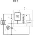
- Fig. 1 schematically shows a block diagram of the power supply device in accordance with the first exemplary embodiment of the present invention.
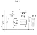
- Fig. 2 shows a detailed block diagram of the second DC/DC converter in accordance with the embodiment.
- Fig. 3 schematically shows a block diagram of another structure of the power supply device in accordance with the embodiment.
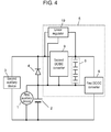
- Fig. 4 schematically shows a block diagram of a structure having a linear regulator of the power supply device in accordance with the embodiment.
- the description will be given on a vehicle having a stop-idling function.
- first auxiliary device 1 is connected in parallel to DC voltage source 2.
- Devices employed for first auxiliary device 1 are the ones that carry a large current, such as a starter and a generator, or the ones that have a wide permissible-voltage-range or the ones that are insusceptible to a momentary stop of operations.
- DC voltage source 2 an electricity storage device with high power density, a lead battery is generally employed.
- Second auxiliary device 3 is connected to DC voltage source 2 via first rectifier 4.
- Devices employed for second auxiliary device 3 are the ones that have a narrow permissible-voltage-range, for example, a car audio system, a navigation system, and various types of electronic control unit (ECU).
- ECU electronice control unit
- first DC/DC converter 6 uses DC voltage source 2 as an input source.
- first DC/DC converter 6 for example, a non-isolated booster circuit or an isolated circuit is employed.
- An output terminal of first DC/DC converter 6 is connected to electricity storage device 8 that is formed of, for example, a plurality of electrical double-layer capacitors.
- electricity storage device 8 is formed of, for example, a plurality of electrical double-layer capacitors.
- an electrical-double-layer capacitor is preferably employed for an energy storage source in terms of its large capacitance and high reliability in charging and discharging repeatedly carried out, it is not limited thereto.
- a secondary battery or different types of capacitor can be employed for electricity storage device 8.
- Electricity storage device 8 is also connected to an input terminal of second DC/DC converter 9.
- First rectifier 4 is connected to an output terminal of second DC/DC converter 9.
- first switch element 10 and second switch element 11 are connected in series to the input terminal to which electricity storage device 8 is connected.
- Inductance element 12 and smoothing capacitor 13 are connected in series so as to be parallel to first switch element 10.
- Smoothing capacitor 13 is disposed at the output terminal of second DC/DC converter and is connected to first rectifier 4.
- Control circuit 14 effects alternate ON/OFF control of first switch element 10 and second switch element 11.
- Control circuit 14 determines an ON/OFF ratio according to output voltage.
- Smoothing capacitor 15 is disposed at the input terminal of second DC/DC converter 9 and is connected to electricity storage device 8.
- Second DC/DC converter 9 is preferably formed of a step-down circuit that changes the ratio of output current to input current according to the step-down ratio of voltage.
- the structure decreases the current flown into electricity storage device 8, contributing to high-speed response and downsized electricity storage device 8.
- second DC/DC converter 9 More preferably employed for second DC/DC converter 9 is a bidirectional converter circuit having a step-down synchronous rectification circuit from the following reasons. As starter current flows with the shape of pulse, DC voltage source 2 has abrupt decrease and increase in voltage. To cope with the decrease, second DC/DC converter 9 increases output. On the other hand, to cope with the abrupt increase, bidirectional connection of the converter allows electric power to return to electricity storage device 8. This provides voltage with stability at a high speed of response.
- the voltage drop can cause malfunction or abnormal stop of a device with a narrow permissible-voltage-range. That is, it becomes necessary to apply input voltage that compensates for the voltage drop.
- DC voltage source 2 while DC voltage source 2 is working with no voltage drop, i.e., under the condition where the output voltage is kept higher than a predetermined value (for example, 7V as described above), DC voltage source 2 supplies second auxiliary device 3 with electric power.
- first DC/DC converter puts electricity storage device 8 on charge so as to compensate for one-time voltage drop at engine restart after stop-idling. Electricity storage device 8 undergoes charging during a charging period other than the engine-restart period, and the charging period is clearly longer than the engine-restart period. This contributes to decreased power-charging rate. Therefore, it becomes possible to make first DC/DC converter 6 smaller in size.
- Electricity storage device 8 is put on charge so as to have a voltage value higher than the total of the maximum amount of decrease in voltage of DC voltage source 2 and the maximum amount of decrease in voltage of electricity storage device 8 that is calculated by multiplying the internal resistance value by maximum current of electricity storage device 8.
- the voltage value calculated above is adequately large for compensation for decrease in voltage of DC voltage source 2.
- first DC/DC converter 6 stops working. First DC/DC converter 6 remains OFF except when electricity storage device 8 is put on charge. The operation control not only reduces loss of first DC/DC converter 6 but also lightens the load on DC voltage source 2. Detecting the charging state of electricity storage device 8, the power supply device effects ON/OFF control of first DC/DC converter 6.
- the energy-storing source as a power supplier is electricity storage device 8, which serves as the input source of second DC/DC converter 9.
- the structure of the embodiment offers a higher response.
- the output current of second DC/DC converter 9 is almost equivalent to the application voltage to second auxiliary device 3, decreasing the amount of electricity that the second DC/DC converter 9 carries.
- the amount of electric power W2 is almost covered by the electric power stored in electricity storage device 8.
- second DC/DC converter 9 may start working upon receiving an external signal, for example, from the side of the vehicle. Receiving a signal earlier than the engine-restart operation allows second DC/DC converter 9 to have a quick start-up, providing output with stability.
- the power supply device with the structure and workings above lightens the load on DC voltage source 2 and electricity storage device 8, increasing the response speed and providing second auxiliary device 3 with a stabilized voltage.
- Fig. 3 schematically shows a block diagram of another structure of the power supply device, which is an improvement over the structure of Fig. 1 .
- the structure of Fig. 3 differs from that of Fig. 1 in that second rectifier 17 is disposed at the input terminal of first DC/DC converter 6.
- Second rectifier 17 protects the circuit from damage caused by the current flow when DC voltage source 2 is connected reverse in polarity.
- disposing second rectifier 17 between electricity storage device 8 and the input terminal of first DC/DC converter 6 prevents the current flow in reverse connection, thereby enhancing reliability of the structure.
- a switch element may be disposed in parallel to second rectifier 17 in Fig. 3 .
- a vehicle-side ECU (not shown) remains the switch element ON at least during the charging operation on electricity storage device 8 by first DC/DC converter 6, the loss caused by the current flown into second rectifier 17 is decreased.
- Fig. 4 schematically shows a block diagram of still another structure of the power supply device, which is an improvement over the structure of Fig. 1 .
- linear regulator 19 is added to the structure of Fig. 1 so as to have input and output shared with second DC/DC converter 9.
- the input of linear regulator 19 is connected to the input of second DC/DC converter 9 and the output of linear regulator 19 is connected to the output of second DC/DC converter 9.
- the response speed of linear regulator 19 is higher than that of a DC/DC converter.
- a response delay can cause a decrease in voltage.
- adding linear regulator 19 to the structure above prevents the voltage decrease corresponding to the response delay, enhancing stability of application voltage to second auxiliary device 3.
- linear regulator 19 has a value slightly lower than that of second DC/DC converter 9.
- linear regulator 19 has no output automatically when the output of second DC/DC converter 9 comes up properly, which minimizes the loss of linear regulator 19 and lightens the load on electricity storage device 8.
- the power supply device of the embodiment provides a stabilized voltage, with a high-speed response, to an auxiliary device, without increasing the load on the DC voltage source and the electricity storage device.
- Fig. 5 schematically shows a block diagram of the power supply device in accordance with the second exemplary embodiment of the present invention.
- Fig. 6 schematically shows a block diagram of another structure of the power supply device of the embodiment.
- the same references are used as in Fig. 1 for similar parts.
- the structure of the embodiment forms a compensation circuit for voltage decrease in a power supply device system for vehicle employing an electrically operated auxiliary device.
- electricity storage device 8 and first rectifier 4 form a parallel circuit, which is connected in series to DC voltage source 2.
- High voltage auxiliary device 22 is connected in parallel to the in-series circuit of DC voltage source 2 and the parallel circuit of electricity storage device 8 and first rectifier 4.
- Mainly employed for high voltage auxiliary device 22 are motor-driven devices, for example, electric power steering, electric brakes, an electric air-conditioner, and electric turbos. Applying voltage higher than that of DC voltage source 2 to these devices allows the motor to have higher torque, increasing in performance.
- a device that exhibits pulse-shaped consumption of electricity may be employed for high voltage auxiliary device 22.
- Wide voltage-range auxiliary device 20 is connected in parallel to DC voltage source 2.
- the wording of "wide voltage-range” auxiliary device above represents an auxiliary device with a wide permissible-voltage range, which capable of operating normally even if the output voltage of DC voltage source 2 decreases to around 7V under the influence of high voltage auxiliary device 22 that consumes a large current in the form of pulse, such as a starter, or which has no ill effect on itself if the device unintentionally comes to a stop.
- narrow voltage-range auxiliary device 24 is connected in parallel to DC voltage source 2 via second rectifier 23.
- narrow voltage-range auxiliary device 24 includes a device with a narrow permissible-voltage-range, such as a car audio system, a navigation system, and a vehicle-side ECU. In these devices, coming to a stop in the middle of operation due to the voltage drop should never be allowed.
- Narrow voltage-range auxiliary device 24 is connected to first input/output terminal 26a of bidirectional DC/DC converter 26.
- the parallel circuit of electricity storage device 8 and first rectifier 4 is connected to second input/output terminal 26b.
- first rectifier 4 prevents the application of the reverse voltage to electricity storage device 8. That is, when electricity storage device 8 is not charged sufficiently at the first start-up, the starter current flows through first rectifier 4.
- a generator (not shown) connected to DC voltage source 2 generates electric power so as to put DC voltage source 2 on charge and provide wide voltage-range auxiliary device 20 and narrow voltage-range auxiliary device 24 with electric power.
- bidirectional DC/DC converter 26 starts charging operation on electricity storage device 8.
- Electricity storage device 8 has to be charged to a voltage higher than the decreased voltage of DC voltage source 2 caused by a large current-flow into high voltage auxiliary device 22, or has to be a high-voltage state required for high voltage auxiliary device 22. This allows narrow voltage-range auxiliary device 24 to maintain compensation voltage higher than a predetermined value (for example, 11V) required for normal operation.
- Electricity storage device 8 is, as described earlier, formed of an electrical double-layer capacitor, which allows the charging voltage to be set to a desired value.
- the charging voltage can be controlled by bidirectional DC/DC converter 26. Furthermore, the total voltage of DC voltage source 2 and electricity storage device 8 can be controlled. In this case, high voltage auxiliary device 22 undergoes application of stabilized voltage with no dependence on change in voltage caused by a charging status or deterioration condition of DC voltage source 2.
- DC voltage source 2 has a battery voltage of 12V and an internal resistance value of 10 m ⁇ .
- output voltage Vb of DC voltage source 2 measures approx. 7V that is lower than a predetermined value of 11V.
- bidirectional DC/DC converter 26 works as follows.
- bidirectional DC/DC converter 26 First, the operating state of bidirectional DC/DC converter 26 is changed before the starter start-up so as to have electricity storage device 8 as input and narrow voltage-range auxiliary device 24 as output. Besides, bidirectional DC/DC converter 26 maintains application voltage Vc at a level before engine-restart. With the control above, bidirectional DC/DC converter 26 can cope with the decrease in voltage Vb of DC voltage source 2 caused by the large-current flow at starter start-up and compensate for the voltage drop for applying voltage Vc to narrow voltage-range auxiliary device 24. Specifically, through the compensation, application voltage Vc to narrow voltage-range auxiliary device 24 is maintained at a predetermined value of 11V.
- the charged voltage of electricity storage device 8 is in a low state due to the current consumption by high voltage auxiliary device 22 and voltage compensation for narrow voltage-range auxiliary device 24. After that, i.e., when the normal operating conditions come back, electricity storage device 8 becomes recharged to a predetermined value by bidirectional DC/DC converter 26. Electricity storage device 8 has a similar voltage drop by high voltage auxiliary device 22 other than the starter. In this case, too, electricity storage device 8 undergoes a similar recharging operation.
- An electric auxiliary device using a motor generally consumes electric power as a large current-flow in a short period.
- electricity storage device 8 supplies electric power consumed in the short period, and the decreased amount of electric power can be covered by charging operation in other periods. This contributes to electric-power averaging, thereby downsizing bidirectional DC/DC converter 26.
- bidirectional DC/DC converter 26 allows the structure to reduce in size and cost.
- Fig. 6 schematically shows a block diagram of still another structure of the power supply device, which is an improvement over the structure of Fig. 5 .
- the structure of Fig. 6 differs from that of Fig. 5 in using isolated bidirectional DC/DC converter 28, instead of a (non-isolated) bidirectional DC/DC converter.
- the output voltage of a non-isolated bidirectional DC/DC converter is calculated as a total of the voltage of DC voltage source 2 and the charged voltage of electricity storage device 8.
- isolated bidirectional DC/DC converter 28 has an output the same as the charged voltage of electricity storage device 8, contributing to a decreased output power.
- the ignition switch On completion of driving, if the ignition switch is turned OFF with the voltage of electricity storage device 8 maintained as high as rated voltage, deterioration of the electrical double-layer capacitor will be accelerated. Discharging electricity storage device 8 at the end of driving can prevent the deterioration.
- the charged voltage of electricity storage device 8 is discharged to a predetermined voltage to improve energy efficiency through the following process.
- dark current a slight amount of current flows through the structure.
- the dark current exerts an influence on the battery life and the engine-start operation after a long period of no-use.
- residual power of electricity storage device 8 is effectively used for the dark current.
- isolated bidirectional DC/DC converter 28 when detecting the engine-stop condition of the vehicle from an ignition-key signal, isolated bidirectional DC/DC converter 28 has electricity storage device 8 as input and narrow voltage-range auxiliary device 24 as output.
- narrow voltage-range auxiliary device 24 When the output voltage of DC/DC converter 28 reaches a level higher than that of DC voltage source 2 but within the range of rated voltage of narrow voltage-range auxiliary device 24, isolated bidirectional DC/DC converter 28 stops working.
- narrow voltage-range auxiliary device 24 carries dark current only, so that the voltage applied to narrow voltage-range auxiliary device 24 gradually decreases from the output voltage of isolated bidirectional DC/DC converter 28 down to around voltage Vb of DC voltage source 2.
- the restart timing of isolated bidirectional DC/DC converter 28 may be set at the moment when voltage Vb is detected, or the moment on lapse of a timer-set suspended time. In this way, isolated bidirectional DC/DC converter 28 outputs the voltage of electricity storage device 8 in the engine-stop period so as to control it to be higher than that of DC voltage source 2. By virtue of the output control of converter 28, there is no dark-current flow from DC voltage source 2 as long as electricity storage device 8 maintains residual power. This lightens the load on DC voltage source 2, and at the same time, the residual power of electricity storage device 8 is effectively used for the dark current. Besides, the intermittent operation of isolated bidirectional DC/DC converter 28 allows electricity storage device 8 to supply narrow voltage-range auxiliary device 24 with dark current on a continual basis. As a result, the operation loss of isolated bidirectional DC/DC converter 28 is decreased. Through the operation above, the charged voltage of electricity storage device 8 is repeatedly discharged to a level that has no ill effect on its reliability (i.e., to a predetermined voltage).
- bidirectional DC/DC converter 26 As is shown in the structure of Fig. 5 .
- DC voltage source 2 is included in the input of bidirectional DC/DC converter 26, by which an extra energy loss is increased at bidirectional DC/DC converter 26.
- isolated bidirectional DC/DC converter 28 has input voltage from electricity storage device 8 only, decreasing energy loss. That is, the structure of Fig. 6 is more preferable than that of Fig. 5 in terms of effective use of energy.
- a switch element for example, formed of an FET may be additionally disposed to each structure of Fig. 5 and Fig. 6 .
- the switch element is connected in parallel with second rectifier 23 and is controlled by a vehicle-side ECU (not shown).
- the ECU effects control of the switch element in a manner so as to maintain OFF when bidirectional DC/DC converter 26 allows electricity storage device 8 to supply narrow voltage-range auxiliary device 24 with electric power and high voltage auxiliary device 22 is in operation.
- the aforementioned control is for compensation for voltage decrease of DC voltage source 24 affected by operating high voltage auxiliary device 22, thereby stabilizing power supply to narrow voltage-range auxiliary device 24, such as an audio system, a navigation system, and various types of ECU.
- narrow voltage-range auxiliary device 24 such as an audio system, a navigation system, and various types of ECU.
- bidirectional DC/DC converter 26 allows electricity storage device 8 to supply narrow voltage-range auxiliary device 24 with electric power
- second rectifier 23 effectively prevents current from flowing to DC voltage source 2 and wide voltage-range auxiliary device 20 from electricity storage device 8, so that narrow voltage-range auxiliary device 24 keeps operating with stability.
- the switch element of FET that maintains OFF, too, in the out-of-use period of the vehicle, can be employed for the circuit that protects reverse connection of DC voltage source 2.
- electricity storage device 8 is charged by electric power of DC voltage source 2
- the switch element is turned ON. This is another advantage of reducing loss caused by current that flows into second rectifier 23.
- the power supply device above When the power supply device above is employed for a vehicle having a regenerating function (that regenerates kinetic energy in the braking process as electric energy by a generator), the following effect is expected.
- the generator In the regenerating process, the generator generates a large current more than 100A in a short period. However, the capacity of the battery as DC voltage source 2 is too small to have the whole amount of the current.
- putting electricity storage device 8 on charge by bidirectional DC/DC converter 26 increases the regeneration amount.
- second rectifier 23 has a voltage drop of about 1V, which develops a large electric-power loss in the form of heat. This arises a problem that second rectifier 23 has a radiator increased in size and weight.
- the structure having the switch element addresses the problem above. Maintaining the switch ON at least during the regenerating process allows the large current to flow in the switch element, reducing electric-power loss at second rectifier 23.
- first input/output terminal 26a outputs electric power not only to narrow voltage-range auxiliary device 24 but also to DC voltage source 2. Therefore, when the power supply device employed for a vehicle having a regenerating function offers a preferable effect-the regeneration allows DC voltage source 2 to put on charge with the electric power stored in electricity storage device 8.
- the structure of the embodiment provides a power supply device capable of stabilizing voltage with a high-speed response, but without placing a heavy load on the DC voltage source and the electricity storage device, and supplying the voltage to a predetermined auxiliary device.
- Fig. 7 schematically shows a block diagram of the power supply device in accordance with the third exemplary embodiment of the present invention.
- the same references are used as in Figs. 1 and 5 for similar parts and in-detail description thereof will be omitted.
- the structure of the embodiment forms a vehicle power supply device having a regenerating function described in the previous embodiment.
- high voltage auxiliary device 22 and wide voltage-range auxiliary device 20 are connected in parallel circuit relation with DC voltage source 2.
- generator 30 for generating electric power by the engine is connected in parallel with the DC voltage source.
- a parallel circuit formed of rectifier 31 and switch element 32 is connected in series to DC voltage source 2.
- Switch element 32 is controlled by vehicle-side ECU 33.
- an FET is employed, like in the first and second exemplary embodiments, for the parallel circuit of rectifier 31 and switch element 32, it is not limited thereto. A similar effect is obtained from a structure where rectifier 31 is disposed independent from switch element 32 having a relay, for example.
- Bidirectional DC/DC converter 26 makes connections to narrow voltage-range auxiliary device 24 at first input/output terminal 26a, and makes connections to electricity storage device 8 at second input/output terminal 26b.
- Generator 30 starts to generate electric power, which is used for charging DC voltage source 2 and supplying to wide voltage-range auxiliary device 20 and narrow voltage-range auxiliary device 24.
- Bidirectional DC/DC converter 26 starts pre-charge operation on electricity storage device 8, having first input/output terminal 26a as input and second input/output terminal 26b as output.
- the start-up of the charging operation on electricity storage device 8 may be set before the engine start-up in response to, for example, a signal of a courtesy switch (not shown).
- vehicle-side ECU 33 When electricity storage device 8 is put on charge by DC voltage source 2 or generator 30, vehicle-side ECU 33 turns ON switch element 32. Maintaining switch element 32 ON allows the charging current to mainly flow in the switch element, thereby reducing power loss at rectifier 31.
- vehicle-side ECU 33 turns ON switch element 32 and effects control of bidirectional DC/DC converter 26 in a manner so as to output electric power to electricity storage device 8.
- the electric power generated by generator 30 is charged to DC voltage source 2, and the power is also charged to electricity storage device 8 via bidirectional DC/DC converter 26.
- the amount of electric power generated in a short time in the braking period is beyond the capacity of DC voltage source 2 that is formed of a lead battery. Therefore, most of the generated power is supplied to electricity storage device 8.
- bidirectional DC/DC converter 26, which has already been in operation quickly puts electricity storage device 8 on charge.
- switch element 32 kept in the ON status reduces heavy loss in electric power at rectifier 31, as is described in the second embodiment.
- the engine restart needs power supply from DC voltage source 2 to high voltage auxiliary device 22 (i.e., the starter). Due to the large current-flow in a short period, the voltage of DC voltage source 2 is plunged into a low level (around 7V) where narrow voltage-range auxiliary device 24 cannot keep working.
- vehicle-side ECU 33 operates as follows.
- vehicle-side ECU 33 turns OFF switch element 32 and effects control of bidirectional DC/DC converter 26 in a manner so as to have second input/output terminal 26b as input and first input/output terminal 26a as output.
- This allows the electric power stored in electricity storage device 8 to be stabilized by bidirectional DC/DC converter 26 and to be applied to narrow voltage-range auxiliary device 24.
- vehicle-side ECU 33 starts up the starter and restarts the engine.
- voltage Vb of DC voltage source 2 decreases to around 7V at that time, bidirectional DC/DC converter 26 maintains voltage Vc of the output terminal at adequate levels (more than 11V) for keep operating narrow voltage-range auxiliary device 24.
- the anode-side voltage i.e., voltage Vb
- the cathode-side voltage i.e., voltage Vc
- switch element 32 is maintained OFF, and accordingly, rectifier 31 is out of operation.
- the electric power of electricity storage device 8 is supplied with stability to narrow voltage-range auxiliary device 24, without being supplied toward DC voltage source 2.
- generator 30 starts up and DC voltage source 2 regains the normal level in voltage and works under normal operating conditions.
- vehicle-side ECU 33 turns ON switch element 32, so that DC voltage source 2 supplies narrow voltage-range auxiliary device 24 with electric power with a small loss in electric power at rectifier 31.
- electricity storage device 8 may supply the auxiliary device with electric power; in the meantime, generator 30 may be brought into a temporary rest.
- the charged voltage of electricity storage device 8 is in a low level because of discharging for voltage compensation for narrow voltage-range auxiliary device 24. After that, i.e., when the normal operating conditions come back, or in the regenerating process, electricity storage device 8 becomes recharged to a predetermined value by bidirectional DC/DC converter 26. Electricity storage device 8 has a similar voltage decrease by high voltage auxiliary device 22 other than the starter. In this case, too, electricity storage device 8 undergoes a similar recharging operation.
- Vehicle-side ECU 33 effects ON/OFF control of switch element 32 as follows:
- switch element 32 may be maintained ON when bidirectional DC/DC converter 26 allows electricity storage device 8 to supply narrow voltage-range auxiliary device 24 with electric power and high voltage auxiliary device 22 is not operating. This allows the electric power fed from first input/output terminal 26a to be supplied not only to narrow voltage-range auxiliary device 24 but also to DC voltage source 2. That is, the electric power, which is stored in electricity storage device 8 by the regeneration process, is also used for charging DC voltage source 2.
- the structure of the embodiment provides a power supply device capable of voltage compensation, with a high-speed response, for narrow voltage-range auxiliary device 24; at the same time, capable of reducing power loss caused by the current flown into rectifier 31.
- the power supply device of the present invention compensates for the voltage drop so as to supply an auxiliary device with stabilized voltage. It is therefore effectively employed for a power supply device for a vehicle with the stop-idling function that consumes a large current.
Landscapes
- Engineering & Computer Science (AREA)
- Power Engineering (AREA)
- Charge And Discharge Circuits For Batteries Or The Like (AREA)
- Control Of Charge By Means Of Generators (AREA)
- Continuous-Control Power Sources That Use Transistors (AREA)
- Dc-Dc Converters (AREA)
Applications Claiming Priority (2)
| Application Number | Priority Date | Filing Date | Title |
|---|---|---|---|
| JP2006188880 | 2006-07-10 | ||
| PCT/JP2007/062780 WO2008007540A1 (fr) | 2006-07-10 | 2007-06-26 | Dispositif d'alimentation |
Publications (1)
| Publication Number | Publication Date |
|---|---|
| EP2040361A1 true EP2040361A1 (fr) | 2009-03-25 |
Family
ID=38923105
Family Applications (1)
| Application Number | Title | Priority Date | Filing Date |
|---|---|---|---|
| EP07767586A Withdrawn EP2040361A1 (fr) | 2006-07-10 | 2007-06-26 | Dispositif d'alimentation |
Country Status (4)
| Country | Link |
|---|---|
| US (1) | US20100231178A1 (fr) |
| EP (1) | EP2040361A1 (fr) |
| JP (1) | JP4835690B2 (fr) |
| WO (1) | WO2008007540A1 (fr) |
Cited By (3)
| Publication number | Priority date | Publication date | Assignee | Title |
|---|---|---|---|---|
| WO2010126654A1 (fr) * | 2009-04-30 | 2010-11-04 | Ge Aviation Systems Llc | Système et procédé pour transférer l'énergie entre un système d'alimentation pour avion et des dispositifs de stockage d'énergie |
| WO2020012005A1 (fr) * | 2018-07-12 | 2020-01-16 | Continental Automotive France | Unité de contrôle embarquée dans un véhicule automobile à élévateur de tension auxiliaire |
| DE102009008255B4 (de) | 2009-02-10 | 2021-12-23 | Bayerische Motoren Werke Aktiengesellschaft | Verfahren und Vorrichtung zum Betrieb eines Energiebordnetzes |
Families Citing this family (32)
| Publication number | Priority date | Publication date | Assignee | Title |
|---|---|---|---|---|
| DE102007056956B4 (de) * | 2007-11-27 | 2009-10-29 | Moosbauer, Peter, Dipl.-Ing.(FH) | Schaltung zur Regelung der Stromversorgung eines Verbrauchers und Verfahren zum Betrieb einer Schaltung |
| DE102008021875A1 (de) * | 2008-03-17 | 2009-10-08 | Fraunhofer-Gesellschaft zur Förderung der angewandten Forschung e.V. | Vorrichtung und Verfahren zum Wandeln eines Potentials |
| JP2010207043A (ja) * | 2009-03-05 | 2010-09-16 | Kito Corp | 電動巻上下装置用電源装置 |
| DE102009028147A1 (de) * | 2009-07-31 | 2011-02-03 | Robert Bosch Gmbh | Schaltungsanordnung für ein Bordnetz |
| JP2011155791A (ja) * | 2010-01-28 | 2011-08-11 | Panasonic Corp | 車両用電源装置 |
| CN101976871B (zh) * | 2010-10-22 | 2013-03-06 | 艾默生网络能源有限公司 | 一种ups电源控制电路和ups电源 |
| US9306465B2 (en) | 2011-06-10 | 2016-04-05 | Lear Corporation | Method for controlling a converter having variable frequency control and system for powering a vehicle load using same |
| DE102012200804A1 (de) * | 2012-01-20 | 2013-07-25 | Continental Automotive Gmbh | Bordnetz und Verfahren zum Betreiben eines Bordnetzes |
| FR2986120B1 (fr) * | 2012-01-23 | 2015-08-21 | Commissariat Energie Atomique | Gestion combinee de deux sources de tension |
| JP5998755B2 (ja) * | 2012-08-30 | 2016-09-28 | マツダ株式会社 | 車両用電源制御装置および方法 |
| US20170155274A1 (en) * | 2014-03-03 | 2017-06-01 | Robert Bosch Gmbh | Topology and control strategy for hybrid storage systems |
| WO2015132631A1 (fr) * | 2014-03-06 | 2015-09-11 | Robert Bosch (Sea) Pte. Ltd. | Système de stockage hybride amélioré |
| JP6173241B2 (ja) * | 2014-03-14 | 2017-08-02 | オムロンオートモーティブエレクトロニクス株式会社 | 電力供給装置 |
| JP2015209058A (ja) | 2014-04-25 | 2015-11-24 | オムロンオートモーティブエレクトロニクス株式会社 | 電源装置 |
| JP2015217919A (ja) * | 2014-05-21 | 2015-12-07 | オムロンオートモーティブエレクトロニクス株式会社 | 車両用電源装置、車両用回生システム |
| JP2015217920A (ja) * | 2014-05-21 | 2015-12-07 | オムロンオートモーティブエレクトロニクス株式会社 | 車両用電源装置、車両用回生システム |
| JP5975068B2 (ja) * | 2014-06-17 | 2016-08-23 | 株式会社豊田自動織機 | 車両の電源装置 |
| JP6242012B2 (ja) * | 2014-10-09 | 2017-12-06 | オムロンオートモーティブエレクトロニクス株式会社 | 電源装置 |
| JP6284496B2 (ja) | 2015-02-20 | 2018-02-28 | オムロンオートモーティブエレクトロニクス株式会社 | 電圧変換装置 |
| US9966840B2 (en) * | 2015-05-01 | 2018-05-08 | Champion Microelectronic Corporation | Switching power supply and improvements thereof |
| JP6541414B2 (ja) * | 2015-05-08 | 2019-07-10 | オムロン株式会社 | 電源供給装置 |
| JP2016213969A (ja) * | 2015-05-08 | 2016-12-15 | オムロンオートモーティブエレクトロニクス株式会社 | 電源供給装置 |
| KR101766040B1 (ko) * | 2015-09-18 | 2017-08-07 | 현대자동차주식회사 | 차량용 배터리 충전 제어 시스템 및 방법 |
| DE112016002218T5 (de) | 2015-11-18 | 2018-04-19 | Next-E Solutions Inc. | Steuervorrichtung, elektrische Speichervorrichtung und elektrisches Speichersystem |
| US10833594B2 (en) * | 2017-05-19 | 2020-11-10 | Infineon Technologies Austria Ag | System and method of controlling a power converter having an LC tank coupled between a switching network and a transformer winding |
| JP6928347B2 (ja) * | 2017-08-02 | 2021-09-01 | NExT−e Solutions株式会社 | 管理装置、蓄電装置、蓄電システム、及び、電気機器 |
| JP6955972B2 (ja) * | 2017-11-13 | 2021-10-27 | NExT−e Solutions株式会社 | 制御装置、制御システム、蓄電装置及びプログラム |
| JP7073865B2 (ja) * | 2018-04-09 | 2022-05-24 | トヨタ自動車株式会社 | 冗長電源システム |
| JP7168912B2 (ja) * | 2019-02-05 | 2022-11-10 | マツダ株式会社 | 車両電源システム |
| US11569681B2 (en) * | 2020-12-04 | 2023-01-31 | Infineon Technologies Austria Ag | Bidirectional battery charge-discharge control |
| US11876439B2 (en) * | 2021-01-14 | 2024-01-16 | Apple Inc. | Mitigation of battery output voltage ripple under pulse load |
| CN114285275B (zh) * | 2021-12-27 | 2023-10-31 | 阳光电源股份有限公司 | 一种电源变换系统及供电系统 |
Family Cites Families (8)
| Publication number | Priority date | Publication date | Assignee | Title |
|---|---|---|---|---|
| JPH04334907A (ja) * | 1991-05-08 | 1992-11-24 | Honda Motor Co Ltd | 電気自動車用充電装置 |
| JP3113159B2 (ja) * | 1994-11-14 | 2000-11-27 | 富士通株式会社 | 電源装置 |
| DE19846319C1 (de) * | 1998-10-08 | 2000-02-17 | Daimler Chrysler Ag | Energieversorgungsschaltung für ein Kraftfahrzeugbordnetz mit zwei Spannungsversorgungszweigen |
| JP3874344B2 (ja) * | 2002-01-17 | 2007-01-31 | 株式会社小松製作所 | ハイブリッド電源システム |
| JP3536070B2 (ja) * | 2002-02-04 | 2004-06-07 | 株式会社ルネサステクノロジ | 半導体装置の製造方法 |
| JP2003237501A (ja) * | 2002-02-19 | 2003-08-27 | Denso Corp | 自動車用電源装置 |
| JP4468708B2 (ja) * | 2004-01-16 | 2010-05-26 | 三菱電機株式会社 | 電源装置 |
| JP4474939B2 (ja) * | 2004-02-20 | 2010-06-09 | トヨタ自動車株式会社 | 車両用電源装置 |
-
2007
- 2007-06-26 WO PCT/JP2007/062780 patent/WO2008007540A1/fr not_active Ceased
- 2007-06-26 EP EP07767586A patent/EP2040361A1/fr not_active Withdrawn
- 2007-06-26 JP JP2008524748A patent/JP4835690B2/ja not_active Expired - Fee Related
- 2007-06-26 US US12/305,959 patent/US20100231178A1/en not_active Abandoned
Non-Patent Citations (1)
| Title |
|---|
| See references of WO2008007540A1 * |
Cited By (7)
| Publication number | Priority date | Publication date | Assignee | Title |
|---|---|---|---|---|
| DE102009008255B4 (de) | 2009-02-10 | 2021-12-23 | Bayerische Motoren Werke Aktiengesellschaft | Verfahren und Vorrichtung zum Betrieb eines Energiebordnetzes |
| WO2010126654A1 (fr) * | 2009-04-30 | 2010-11-04 | Ge Aviation Systems Llc | Système et procédé pour transférer l'énergie entre un système d'alimentation pour avion et des dispositifs de stockage d'énergie |
| US8058749B2 (en) | 2009-04-30 | 2011-11-15 | Ge Aviation Systems, Llc | System and method for transferring power between an aircraft power system and energy storage devices |
| CN102414949A (zh) * | 2009-04-30 | 2012-04-11 | 通用电气航空系统有限责任公司 | 用于在飞行器电力系统与储能装置之间传递功率的系统和方法 |
| CN104993507A (zh) * | 2009-04-30 | 2015-10-21 | 通用电气航空系统有限责任公司 | 用于在飞行器电力系统与储能装置之间传递功率的系统和方法 |
| WO2020012005A1 (fr) * | 2018-07-12 | 2020-01-16 | Continental Automotive France | Unité de contrôle embarquée dans un véhicule automobile à élévateur de tension auxiliaire |
| FR3083927A1 (fr) * | 2018-07-12 | 2020-01-17 | Continental Automotive France | Unite de controle embarquee dans un vehicule automobile a elevateur de tension auxiliaire |
Also Published As
| Publication number | Publication date |
|---|---|
| JPWO2008007540A1 (ja) | 2009-12-10 |
| US20100231178A1 (en) | 2010-09-16 |
| WO2008007540A1 (fr) | 2008-01-17 |
| JP4835690B2 (ja) | 2011-12-14 |
Similar Documents
| Publication | Publication Date | Title |
|---|---|---|
| EP2040361A1 (fr) | Dispositif d'alimentation | |
| JP4862823B2 (ja) | 電源安定化装置およびそれを用いた車両 | |
| CN102470810B (zh) | 用于车载电网的线路装置以及运行方法 | |
| US7568537B2 (en) | Vehicle propulsion system | |
| JP3676184B2 (ja) | 車両用電源装置 | |
| CN101175917B (zh) | 发动机起动装置 | |
| JP4893368B2 (ja) | 電源装置 | |
| US20090229898A1 (en) | Controller for Electric Storage Device and Vehicle with Controller for Electric Storage Device | |
| US20060145536A1 (en) | Device for supplying power to a two-voltage vehicle electric system | |
| US20090250999A1 (en) | Micro-hybrid device for motor vehicle | |
| JP2006515242A (ja) | 車両電装システム用電源回路 | |
| CN109747420B (zh) | 车辆用电源系统 | |
| CN109747437B (zh) | 车辆用电源系统 | |
| US9475456B2 (en) | Battery system for micro-hybrid vehicles comprising high-efficiency consumers | |
| WO2017154778A1 (fr) | Dispositif de commande de véhicule hybride | |
| JP4876773B2 (ja) | 電源装置 | |
| JP2009225530A (ja) | 車両用電源装置及びこれに用いる制御装置 | |
| KR20140068556A (ko) | 전기자동차용 직류 변환장치의 제어방법 | |
| JP5915390B2 (ja) | 車両用電源制御方法及び装置 | |
| CN101689766B (zh) | 电力供应系统 | |
| JP4166753B2 (ja) | 内燃機関を有する自動車の電力供給のためのシステム | |
| JP2007300693A (ja) | 車両用マルチ電圧対応電源システム | |
| JP5076918B2 (ja) | 蓄電装置 | |
| JP2014171309A (ja) | 平滑コンデンサ放電制御装置 | |
| KR102030179B1 (ko) | 마이크로 하이브리드 시스템용 전력관리장치 |
Legal Events
| Date | Code | Title | Description |
|---|---|---|---|
| PUAI | Public reference made under article 153(3) epc to a published international application that has entered the european phase |
Free format text: ORIGINAL CODE: 0009012 |
|
| 17P | Request for examination filed |
Effective date: 20081217 |
|
| AK | Designated contracting states |
Kind code of ref document: A1 Designated state(s): AT BE BG CH CY CZ DE DK EE ES FI FR GB GR HU IE IS IT LI LT LU LV MC MT NL PL PT RO SE SI SK TR |
|
| AX | Request for extension of the european patent |
Extension state: AL BA HR MK RS |
|
| STAA | Information on the status of an ep patent application or granted ep patent |
Free format text: STATUS: THE APPLICATION HAS BEEN WITHDRAWN |
|
| 18W | Application withdrawn |
Effective date: 20090429 |