EP2040366A1 - Elektrostatischer motor - Google Patents
Elektrostatischer motor Download PDFInfo
- Publication number
- EP2040366A1 EP2040366A1 EP07744875A EP07744875A EP2040366A1 EP 2040366 A1 EP2040366 A1 EP 2040366A1 EP 07744875 A EP07744875 A EP 07744875A EP 07744875 A EP07744875 A EP 07744875A EP 2040366 A1 EP2040366 A1 EP 2040366A1
- Authority
- EP
- European Patent Office
- Prior art keywords
- electrodes
- stator
- electrostatic motor
- rotor
- motor according
- Prior art date
- Legal status (The legal status is an assumption and is not a legal conclusion. Google has not performed a legal analysis and makes no representation as to the accuracy of the status listed.)
- Granted
Links
Images


Classifications
-
- H—ELECTRICITY
- H02—GENERATION; CONVERSION OR DISTRIBUTION OF ELECTRIC POWER
- H02N—ELECTRIC MACHINES NOT OTHERWISE PROVIDED FOR
- H02N1/00—Electrostatic generators or motors using a solid moving electrostatic charge carrier
- H02N1/002—Electrostatic motors
- H02N1/004—Electrostatic motors in which a body is moved along a path due to interaction with an electric field travelling along the path
Definitions
- the present invention relates to an electrostatic motor that rotationally drives using electrostatic force, and in particular to an electrostatic motor that rotationally drives by generating a high electric field in a vacuum.
- Electrostatic motors that rotationally drive using electrostatic force are also known (e.g., Japanese Patent Application Laid-Open No. 8-88984 , and Study of Servo System using Electrostatic Motors written by Akio Yamamoto et al., www.intellect.pe.u-tokyo.ac.jp/japanese/dissertation_j/yamamoto.html)
- an object of this invention is to provide an electrostatic motor that generates a strong electric field in a vacuum so that it can rotationally drive with sufficient driving force.
- Another object of the present invention is to provide an electrostatic motor designed so as to prevent dielectric breakdown, creeping discharge, spark discharge, and the like to operate in a strong electric field, and also to be lightweight.
- an electrostatic motor according the present invention has the characteristics described below.
- a first aspect of the invention is an electrostatic motor characterized in that a disc-shaped stator and a disc-shaped rotor are disposed opposite each other in a vacuum container such that the stator is fixed to the main body of the vacuum container and the rotor is pivotally supported on the main body of the vacuum container so as to freely rotate via a rotating shaft;
- the stator has first electrodes and second electrodes electrically insulated by an insulator and attached to electrode supports so as to alternate along the circumferences of the electrode supports;
- the rotor has first electrodes and second electrodes electrically insulated by an insulator and attached to electrode supports so as to alternate along the circumferences of the electrode supports;
- the first and second electrodes on the stator side are each arranged at a spacing of two or more rows at a predetermined distance from the center of the rotating shaft;
- the first and second electrodes on the rotor side are each arranged at a predetermined distance from the center of the rotating shaft, and intermediate between the rows of the first and second electrodes on the
- a second aspect of the invention is the electrostatic motor of the first aspect described above, characterized in that the first and second electrodes on the stator side and the first and second electrodes on the rotor side are each pin-shaped and are each arranged parallel to the axial direction of the rotating shaft.
- a third aspect of the invention is the electrostatic motor of the first or second aspect described above, characterized in that the electrode supports of the first and second electrodes on the stator side, and the electrode supports of the first and second electrodes on the rotor side are insulatively supported by the insulators respectively so as to allow sufficient creepage distance.
- a fourth aspect of the invention is the electrostatic motor of any one of the first to third aspects described above, characterized in that the insulators on the stator side and the rotor side each have one or a plurality of grooves formed thereon.
- a fifth aspect of the invention is the electrostatic motor of any one of the first to fourth aspects described above, characterized in that the ends of the first and second electrodes on the stator side and the ends of the first and second electrodes on the rotor side are round in shape.
- a sixth aspect of the invention is the electrostatic motor of any one of the first to fifth aspects described above, characterized in that stainless steel is used for metallic components disposed in the vacuum container and inorganic insulator is used as insulating components.
- a seventh aspect of the invention is the electrostatic motor of any one of the first to sixth aspects described above, characterized in that a nonmagnetic material is used as the metallic components disposed in the vacuum container.
- An eighth aspect of the invention is the electrostatic motor of any one of the first to seventh aspects described above, comprising an encoder including a slit plate and a sensor that detect the relative position between the first and second electrodes on the stator side and the first and second electrodes on the rotor side.
- a ninth aspect of the invention is the electrostatic motor of any one of the first to eighth aspects described above, characterized in that a gas-absorbing material is deposited on components disposed in the vacuum container.
- the present invention adopts the foregoing configuration in which the first and second electrodes attached to the electrode supports of the stator and the rotor are located within the vacuum. Accordingly, unlike a conventional electrostatic motor in which groups of electrodes are supported by an insulator or insulators, the present invention prevents dielectric breakdown even if there is a strong electric field between the electrodes. This results in output as high as or higher than that obtained by an electromagnetic motor. Accordingly, an electrostatic motor that generates a strong electric field in the vacuum such that it can rotationally drive with sufficient driving force can be provided. An electrostatic motor that can drive in a high, clean vacuum is applicable, for example, in semiconductor manufacturing apparatuses. In addition, the electrostatic motor is free from windage loss, thus offering improved efficiency. Moreover, an electrostatic motor that drives in a strong electric field generated between the electrodes allows practical applications including small or large motors, and achieves high output and weight reduction.
- the electrode supports are insulatively supported and grooves are formed in the insulator, allowing sufficient distance for creepage. Accordingly, an electrostatic motor effectively prevents dielectric breakdown, creeping discharge, spark discharge, and other concerns, and generates a strong electric field.
- the electrostatic motor in the electrostatic motor according to the present invention, a stainless steel etc. or an inorganic insulator that produce less residual gas, such as porcelain or glass, are used as components. Therefore, the electrostatic motor can be used in the clean vacuum. Further, using a nonmagnetic material as a metallic components results in a nonmagnetic motor, which can be used in a strong magnetic field.
- the electrostatic motor according to the present invention uses no heavy magnetic materials as metallic components and is therefore lighter in weight than conventional ones.
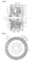
- FIG. 1 shows a vertical section of an electrostatic motor according to the first embodiment of the present invention.
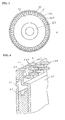
- FIG 2 is a plan view of a stator in the first embodiment
- FIG. 3 is a plan view of a rotor in the first embodiment.
- FIG 4 is a partially-detailed schematic view of the first and second electrodes of the stator in the first embodiment.
- disc-shaped stator S and disc-shaped rotor R are disposed opposite to each other in vacuum container 11, and stator S is fixed to the main body of the vacuum container 11.
- the electrostatic motor in the first embodiment is operable in the vacuum of 3Pa or less.
- first electrodes 34A are fixed to electrode supports 31 on the stator S side.
- the first electrodes 34A are arranged in two rows at a predetermined distance from the center of rotating shaft 1 (i.e., the center of motor base 10).
- second electrodes 34B are fixed to other electrode supports 32 on the stator S side.
- the first electrodes 34A and the second electrodes 34B are arranged so as to alternate.
- the first and second electrodes 34A, 34B are disposed along the circumferences of the electrode substrates 31, 32 respectively at regular intervals parallel to the rotating shaft 1 such that the first and second electrodes 34A, 34B are radially fixed in two rows.
- the electrode supports 31, 32 with the first and second electrodes 34A, 34B respectively are fixed on an insulator 33, which is mounted on the motor base 10 (i.e., the main body of the vacuum container 11).
- the insulator 33 provides sufficient insulating thickness and creepage distance, and has a plurality of grooves formed to prevent creeping discharge.
- sufficient insulating thickness should be equal to or greater than the breakdown voltage of the insulator, and sufficient creepage distance is several times or more larger than this thickness.
- the number of grooves, groove shape, groove depth, and other characteristics, may be set as needed according to the size and application of the electrostatic motor.
- a first electrode 44A is fixed to each electrode supports 41 on the rotor R side. These first electrodes 44A are arranged in one row at a predetermined distance from the center of the rotating shaft 1. Also, disposed on each of the other electrode supports 42, on the rotor R side is a second electrode 44B. As shown in FIG. 3 , the first electrodes 44A and the second electrodes 44B are arranged so as to alternate like those on the stator S side. The first and second electrodes 44A, 44B are disposed along the circumferences of the electrode supports 41, 42 respectively at regular intervals parallel to the rotating shaft 1 such that the first and second electrodes 44A, 44B are radially fixed in one row.
- the electrode supports 41, 42 with the first and second electrodes 44A, 44B respectively are fixed on an insulator 43, which is mounted on the rotating shaft 1.
- the insulator 43 provides sufficient insulating thickness and creepage distance, and has a plurality of grooves formed to prevent creeping discharge.
- the number of grooves, groove shape, groove depth, and other characteristics may be set as needed according to the size and application of the electrostatic motor.
- the first and second electrodes 44A, 44B on the rotor R side are fixed on the supports 41, 42 respectively at regular intervals parallel to the rotating shaft 1, like the first and second electrodes 34A, 34B on the stator S side.
- the positions of the first and second electrodes 44A, 44B on the rotor R side from the center of the rotating shaft 1 are in the middle of the rows of the first and second electrodes 34A and 34B on the stator S side so that the rotor R is rotationally drivable.
- the first electrode 34A, second electrode 34B, first electrode 44A and second electrode 44B are pin-shaped. It is preferable that the ends of the electrodes are round in order to prevent discharge between them. The shape of these electrodes, however, is not limited to pin-shape.
- Power is supplied to the electrodes 44A, 44B on the rotor R side through slip rings 51, 52 and brushes 61, 62.
- An encoder is composed by adopting an optical system (i.e., a slit plate 7 and a sensor 8) or a magnetic system (i.e., a magnetic disc and a sensor). In this embodiment, the former is used.
- the timing of the supply of power to the first and second electrodes 44A, 44B on the rotor R side is detected by the sensor 8, and the detected result is subjected to signal processing by a drive circuit (not shown).
- a high voltage (approximately 1 to 100kV) is outputted and supplied to the first and second electrodes 44A, 44B.
- a vacuum seal 9 is attached to the motor base 10 in order to maintain the vacuum within the electrostatic motor.
- the present invention uses an electrostatic motor that operates in the vacuum.
- the present invention needless to say, functions as an electrostatic motor even in insulation gas such as SF6 gas.
- first and second electrodes 34A and 34b respectively on the stator S side are arranged in two rows, whereas the first and second electrodes 44A and 44b respectively on the rotor R side are arranged in one row.
- the number of rows is not limited to only one, as two or more rows may also be set.
- stainless steel or the like that produce less residual gas may be used as metallic components that are placed in the vacuum container 11 (e.g., the first and second electrodes 34A, 34B, electrode supports 31, 32, first and second electrodes 44A, 44B, and electrode supports 41, 42).
- an inorganic insulator such as porcelain or glass, which produces less residual gas, may be used as an insulating components. The usability of the electrostatic motor in the clean vacuum can thereby be ensured. It is also effective to deposit a gas absorbing material (i.e., gettering substance), such as titanium, vanadium, tantalum, or zirconium, on components used in the vacuum container 11.
- using a nonmagnetic material as the metallic components used in the vacuum container 11 enables a nonmagnetic motor that can be used in a strong magnetic field. Additionally, no heavy magnetic material is used as the metallic components, thus contributing to weight reduction as well.
- the electrostatic motor is configured so that the first and second electrodes 44A, 44B on the rotor R side freely move along the circumference between the first and second electrodes 34A, 34B on the stator S side, the first and second electrodes 44B, 44A are positively and negatively charged respectively by applying a high positive voltage (1 to 100kV or so) to the electrode supports 42.
- a high positive voltage (1 to 100kV or so)
- the direction of thrust i.e., rotating force
- the magnitude and time of the voltage greatly affect the magnitude of the thrust (rotating force).
- FIG 6 illustrates the principle of the action of the electrostatic motor by showing only the first and second electrodes 34A, 34B on the stator S side and the first and second electrodes 44A, 44B on the rotor R side.
- a location i.e., location X1
- a positive potential is applied to the second electrode 44B.
- each of the second electrodes 44B switches to a location (i.e., location X2) that is immediately before first electrodes 34A.
- Second electrode 44B repeats this switching operation each time the positional timing of the second electrode 44B is detected by the signal of the encoder sensor 8.
- FIG. 7 shows the voltage waveforms of the first and second electrodes 44A, 44B on the rotor R side (wherein T0 represents the time at location X0, and T1 and T2 represent times at locations X1 and X2 respectively).
- FIG. 8 shows a vertical section of an electrostatic motor according to the second embodiment.
- elements identical to those in the illustrations of the first embodiment are labeled with the same symbols and duplicate explanation of these elements is avoided.
- first electrodes 34A and three rows of second electrodes 34B are disposed along the circumferences of electrode supports 31, 32 respectively, on the stator S side.
- two rows of first electrodes 44A and two rows of second electrodes 44B are disposed along the circumferences of electrode supports 41, 42 respectively.
- an electrostatic motor with a high output is produced by increasing the number of electrodes.
- FIG 9 shows a vertical section of the electrostatic motor according to the third embodiment.
- elements identical to those in the illustrations of the first embodiment are labeled with the same symbols and duplicate explanation of these elements is avoided.
- the encoder, the slip rings, and the brushes are not shown.
- first electrodes 44A are extended from both sides of each of electrode supports 41 on the rotor R side
- second electrodes 44B are also extended from both sides of each of electrode supports 42 on the rotor R side. This allows an output that is twice as high as that of an electrostatic motor with cantilever structured electrodes in the first embodiment.
- first and second electrodes 34A, 34B may be extended from both sides of the electrode supports 31 and 32, respectively, on the stator S side, and the rotors R and stators S may be stacked in more than one stage in an axial direction.
- FIG. 10 shows a vertical section of the electrostatic motor according to the fourth embodiment, in which first and second electrodes on the stator side and first and second electrodes on the rotor side are radially arranged with respect to the center of the rotating shaft.
- FIGS. 11,12 show vertical section of the stator and rotor, respectively, according to the fourth embodiment. Also in FIGS. 10 to 12 , elements identical to those in illustrations of the first embodiment are labeled with the same symbols and duplicate explanation of these elements is avoided. The encoder, the slip rings, and the brushes are not shown.
- the positional relations between the electrode supports 31, 32, insulator 33, first and second electrodes 34A, 34B on the stator S side, and the electrode supports 41, 42, insulator 43, and first and second electrodes 44A, 44B on the rotor R side differ from those in the first to third embodiments.
- first electrodes 44A are passed through the comparatively large holes of a pipe-like electrode support 41, then firmly inserted, toward the axis, into the pipe-like electrode support 42 with many holes, and thus fixed in position.
- Second electrodes 44B are fixed to the electrode support 41.
- first and second electrodes 34A, 34B are fixed to the electrode supports 31, 32, respectively, along the axis.
- the electrode supports 31, 32 are fixed to a motor base 10 or the body of a vacuum container 11 via the insulator 33.
- the electrode supports 41, 42 are connected to a rotating body 12 and a rotating shaft 1 via an insulator 43.
- the configuration in the fourth embodiment ensures effects as excellent as those in the first to third embodiments.
Landscapes
- Permanent Magnet Type Synchronous Machine (AREA)
- Micromachines (AREA)
- Ignition Installations For Internal Combustion Engines (AREA)
Applications Claiming Priority (2)
| Application Number | Priority Date | Filing Date | Title |
|---|---|---|---|
| JP2006167247A JP4837449B2 (ja) | 2006-06-16 | 2006-06-16 | 静電モータ |
| PCT/JP2007/061546 WO2007145131A1 (ja) | 2006-06-16 | 2007-06-07 | 静電モータ |
Publications (3)
| Publication Number | Publication Date |
|---|---|
| EP2040366A1 true EP2040366A1 (de) | 2009-03-25 |
| EP2040366A4 EP2040366A4 (de) | 2012-07-04 |
| EP2040366B1 EP2040366B1 (de) | 2017-11-08 |
Family
ID=38831646
Family Applications (1)
| Application Number | Title | Priority Date | Filing Date |
|---|---|---|---|
| EP07744875.1A Not-in-force EP2040366B1 (de) | 2006-06-16 | 2007-06-07 | Elektrostatischer motor |
Country Status (6)
| Country | Link |
|---|---|
| US (2) | US8278797B2 (de) |
| EP (1) | EP2040366B1 (de) |
| JP (1) | JP4837449B2 (de) |
| CA (1) | CA2656897C (de) |
| RU (1) | RU2430269C2 (de) |
| WO (1) | WO2007145131A1 (de) |
Cited By (4)
| Publication number | Priority date | Publication date | Assignee | Title |
|---|---|---|---|---|
| WO2009115646A1 (en) * | 2008-03-19 | 2009-09-24 | Lightway | Device and method for generating force and/or movement |
| EP2845291A4 (de) * | 2012-05-04 | 2016-01-20 | Weston Johnson | Elektrostatische maschine |
| US9899937B2 (en) | 2015-01-16 | 2018-02-20 | Wisconsin Alumni Research Foundation | Peg-style electrostatic rotating machine |
| US10243485B2 (en) | 2015-05-18 | 2019-03-26 | Wisconsin Alumni Research Foundation | Peg-style electrostatic rotating machine employing dielectric sleeves |
Families Citing this family (32)
| Publication number | Priority date | Publication date | Assignee | Title |
|---|---|---|---|---|
| JP5154303B2 (ja) * | 2008-05-20 | 2013-02-27 | 株式会社新生工業 | 静電モータ用駆動回路 |
| JP2011223745A (ja) * | 2010-04-09 | 2011-11-04 | Shinsei Kogyo:Kk | 静電モータ |
| JP5661321B2 (ja) * | 2010-04-09 | 2015-01-28 | 株式会社新生工業 | 静電モータ |
| JP5505365B2 (ja) * | 2011-04-28 | 2014-05-28 | 信越半導体株式会社 | 誘導加熱コイルにおける放電防止用絶縁部材及びこれを用いた単結晶製造装置並びに単結晶製造方法 |
| JP5945102B2 (ja) * | 2011-09-01 | 2016-07-05 | 学校法人 関西大学 | 発電装置 |
| JPWO2013153913A1 (ja) * | 2012-04-13 | 2015-12-17 | 株式会社根本杏林堂 | 薬液注入装置 |
| MD650Z (ro) * | 2012-10-29 | 2014-01-31 | Институт Прикладной Физики Академии Наук Молдовы | Motor electrostatic |
| JP5611311B2 (ja) * | 2012-12-04 | 2014-10-22 | 株式会社新生工業 | 静電モータ用駆動回路、静電モータ、及び駆動方法 |
| US9270203B2 (en) * | 2013-03-12 | 2016-02-23 | Lawrence Livermore National Security, Llc | Electrode geometry for electrostatic generators and motors |
| US9866148B2 (en) | 2014-10-05 | 2018-01-09 | C-Motive Technologies Inc. | Electrostatic machine system and method of operation |
| US9806639B2 (en) | 2015-04-29 | 2017-10-31 | General Electric Company | Dielectric fluids for linear switched capacitive devices |
| US10504656B2 (en) | 2015-04-29 | 2019-12-10 | General Electric Company | Electrodes for linear switched capacitive devices |
| US20170033712A1 (en) * | 2015-07-31 | 2017-02-02 | Nathanial Henry Lewis | Motor powered by electrostatic forces |
| US9748867B2 (en) | 2015-08-03 | 2017-08-29 | General Electric Company | Control system for linear switched capacitive devices |
| US10122301B2 (en) | 2015-08-19 | 2018-11-06 | Lawrence Livermore National Security, Llc | Pulsed start-up system for electrostatic generators |
| US10882053B2 (en) | 2016-06-14 | 2021-01-05 | Agentis Air Llc | Electrostatic air filter |
| US20170354980A1 (en) | 2016-06-14 | 2017-12-14 | Pacific Air Filtration Holdings, LLC | Collecting electrode |
| US11121604B2 (en) | 2016-07-05 | 2021-09-14 | Lawrence Livermore National Security, Llc | Electrostatic generator electrode-centering and seismic-isolation system for flywheel-based energy storage modules |
| US10541586B2 (en) | 2016-07-05 | 2020-01-21 | Lawrence Livermore National Security, Llc | Electrostatic generator electrode-centering and seismic-isolation system for flywheel-based energy storage modules |
| US10828646B2 (en) | 2016-07-18 | 2020-11-10 | Agentis Air Llc | Electrostatic air filter |
| JP7083351B2 (ja) | 2016-11-08 | 2022-06-10 | シー-モーティヴ テクノロジーズ インコーポレイテッド | 静電機械システムおよび動作方法 |
| WO2019051292A2 (en) * | 2017-09-11 | 2019-03-14 | TransVolt International Energy Corporation | ELECTRIC MACHINE WITH ELECTRODES HAVING MODIFIED SHAPES |
| US10958191B2 (en) | 2018-02-15 | 2021-03-23 | The Charles Stark Draper Laboratory, Inc. | Electrostatic motor |
| US12113460B2 (en) | 2018-11-13 | 2024-10-08 | C-Motive Technologies, Inc. | Electrostatic machine system and method of operation |
| US10875034B2 (en) | 2018-12-13 | 2020-12-29 | Agentis Air Llc | Electrostatic precipitator |
| US10792673B2 (en) | 2018-12-13 | 2020-10-06 | Agentis Air Llc | Electrostatic air cleaner |
| RU2703256C1 (ru) * | 2018-12-29 | 2019-10-16 | Николай Иванович Кузин | Электростатический двигатель |
| CN109441851B (zh) * | 2019-01-16 | 2024-07-12 | 北京航空航天大学 | 一种基于静电驱动的扇叶及其混合驱动方法 |
| EP4082097A4 (de) * | 2019-12-28 | 2024-02-07 | Lawrence Livermore National Security, LLC | System zur elektrodenzentrierung und zur seismischen isolierung eines elektrostatischen generators |
| EP4085521A4 (de) | 2020-01-03 | 2024-03-06 | C-Motive Technologies Inc. | Elektrostatischer motor mit flüssigkeitsmanagement-eigenschaften |
| US20240195328A1 (en) * | 2022-12-07 | 2024-06-13 | Ion Power Group, Llc | Electrostatic Motor |
| JP2025012052A (ja) * | 2023-07-12 | 2025-01-24 | 株式会社デンソー | 静電モータ、および静電モータの製造方法 |
Family Cites Families (17)
| Publication number | Priority date | Publication date | Assignee | Title |
|---|---|---|---|---|
| DE1112570B (de) | 1953-07-21 | 1961-08-10 | Georg A Holzapfel | Elektrostatischer Drehfeldmotor |
| US2843767A (en) * | 1956-03-19 | 1958-07-15 | Heckethorn Mfg & Supply Co | Electrostatic generator |
| US3094653A (en) * | 1961-05-22 | 1963-06-18 | Tylan Corp | Electrostatic generator |
| NL6605612A (de) * | 1966-04-27 | 1967-10-30 | ||
| NL6605934A (de) * | 1966-05-03 | 1967-11-06 | ||
| JPS6387181A (ja) | 1986-09-27 | 1988-04-18 | Kanichiro Sugano | 静電4相電界回転装置 |
| FR2658960A1 (fr) | 1990-02-23 | 1991-08-30 | Asulab Sa | Micromoteur electrostatique a champ radial realise par microfabrication photolithographique et procede de realisation d'un tel micromoteur. |
| JP3471380B2 (ja) | 1992-12-28 | 2003-12-02 | 松下電器産業株式会社 | 静電モータ |
| JPH0866058A (ja) | 1994-08-11 | 1996-03-08 | Kanichiro Sugano | 静電4相電界回転機並びに電界相制御装置 |
| JP3452739B2 (ja) | 1996-11-25 | 2003-09-29 | アスモ株式会社 | 静電アクチュエータ |
| US6163098A (en) * | 1999-01-14 | 2000-12-19 | Sharper Image Corporation | Electro-kinetic air refreshener-conditioner with optional night light |
| JP2001016874A (ja) | 1999-06-29 | 2001-01-19 | Asmo Co Ltd | 静電アクチュエータ |
| CA2284188C (en) * | 1999-09-15 | 2002-01-29 | Daniel Gendron | High efficiency alternating and direct current electrostatic motor |
| DE60326962D1 (de) * | 2002-08-06 | 2009-05-14 | Ricoh Kk | Durch ein halbleiterherstellungsverfahren gebildetes elektrostatisches stellglied |
| JP3886494B2 (ja) | 2004-01-23 | 2007-02-28 | ファナック株式会社 | 固定子用及び移動子用のフィルム型電極及び静電モータ |
| JP4384012B2 (ja) * | 2004-11-08 | 2009-12-16 | 株式会社東芝 | 静電アクチュエータ及びその駆動方法 |
| JP2007143299A (ja) * | 2005-11-18 | 2007-06-07 | Alps Electric Co Ltd | 静電モータ |
-
2006
- 2006-06-16 JP JP2006167247A patent/JP4837449B2/ja not_active Expired - Fee Related
-
2007
- 2007-06-07 CA CA2656897A patent/CA2656897C/en active Active
- 2007-06-07 EP EP07744875.1A patent/EP2040366B1/de not_active Not-in-force
- 2007-06-07 US US12/308,366 patent/US8278797B2/en active Active
- 2007-06-07 WO PCT/JP2007/061546 patent/WO2007145131A1/ja not_active Ceased
- 2007-06-07 RU RU2008152022/06A patent/RU2430269C2/ru active
-
2012
- 2012-06-25 US US13/531,864 patent/US8779647B2/en not_active Expired - Fee Related
Cited By (4)
| Publication number | Priority date | Publication date | Assignee | Title |
|---|---|---|---|---|
| WO2009115646A1 (en) * | 2008-03-19 | 2009-09-24 | Lightway | Device and method for generating force and/or movement |
| EP2845291A4 (de) * | 2012-05-04 | 2016-01-20 | Weston Johnson | Elektrostatische maschine |
| US9899937B2 (en) | 2015-01-16 | 2018-02-20 | Wisconsin Alumni Research Foundation | Peg-style electrostatic rotating machine |
| US10243485B2 (en) | 2015-05-18 | 2019-03-26 | Wisconsin Alumni Research Foundation | Peg-style electrostatic rotating machine employing dielectric sleeves |
Also Published As
| Publication number | Publication date |
|---|---|
| US20100164322A1 (en) | 2010-07-01 |
| US8278797B2 (en) | 2012-10-02 |
| US8779647B2 (en) | 2014-07-15 |
| US20120274177A1 (en) | 2012-11-01 |
| RU2008152022A (ru) | 2010-08-10 |
| JP4837449B2 (ja) | 2011-12-14 |
| EP2040366A4 (de) | 2012-07-04 |
| CA2656897A1 (en) | 2007-12-21 |
| JP2007336735A (ja) | 2007-12-27 |
| RU2430269C2 (ru) | 2011-09-27 |
| CA2656897C (en) | 2016-06-21 |
| WO2007145131A1 (ja) | 2007-12-21 |
| EP2040366B1 (de) | 2017-11-08 |
Similar Documents
| Publication | Publication Date | Title |
|---|---|---|
| US8278797B2 (en) | Electrostatic motor | |
| US8643249B2 (en) | Electrostatic generator/motor configurations | |
| EP0271108B1 (de) | Elektrostatischer Motor | |
| US9184676B2 (en) | Varying capacitance rotating electrical machine | |
| US4760302A (en) | Electric field machine | |
| US9899937B2 (en) | Peg-style electrostatic rotating machine | |
| US20050006980A1 (en) | Electrostatic actuator with fault tolerant electrode structure | |
| US4642504A (en) | Electric field machine | |
| US9614462B2 (en) | Rippled disc electrostatic generator/motor configurations utilizing magnetic insulation | |
| JP5661321B2 (ja) | 静電モータ | |
| JP5154303B2 (ja) | 静電モータ用駆動回路 | |
| JP5611311B2 (ja) | 静電モータ用駆動回路、静電モータ、及び駆動方法 | |
| JP2011223745A (ja) | 静電モータ | |
| EP1368888B1 (de) | Hocheffizienter elektrostatischer motor für wechsel- und gleichstrom | |
| JP7282365B2 (ja) | 静電誘導型発電素子に使用される電極基板 | |
| JP6221420B2 (ja) | 静電電動機 | |
| WO2009037455A2 (en) | Commutators | |
| KR100353454B1 (ko) | 압전형스텝모터 | |
| JP2003047226A (ja) | コイルレスマグネット発電機 | |
| SU1431014A1 (ru) | Ударный генератор | |
| JPH04305260A (ja) | 電気集じん機用パルス電源 | |
| US20090033171A1 (en) | Continuous direct current generator | |
| KR19990036170A (ko) | 압전형 스텝 모터 | |
| JPH06315280A (ja) | 静電アクチュエータ | |
| JPH08237964A (ja) | 静電アクチュエータ |
Legal Events
| Date | Code | Title | Description |
|---|---|---|---|
| PUAI | Public reference made under article 153(3) epc to a published international application that has entered the european phase |
Free format text: ORIGINAL CODE: 0009012 |
|
| 17P | Request for examination filed |
Effective date: 20081229 |
|
| AK | Designated contracting states |
Kind code of ref document: A1 Designated state(s): AT BE BG CH CY CZ DE DK EE ES FI FR GB GR HU IE IS IT LI LT LU LV MC MT NL PL PT RO SE SI SK TR |
|
| AX | Request for extension of the european patent |
Extension state: AL BA HR MK RS |
|
| A4 | Supplementary search report drawn up and despatched |
Effective date: 20120604 |
|
| RIC1 | Information provided on ipc code assigned before grant |
Ipc: H02N 1/00 20060101AFI20120529BHEP |
|
| DAX | Request for extension of the european patent (deleted) | ||
| 17Q | First examination report despatched |
Effective date: 20130130 |
|
| GRAP | Despatch of communication of intention to grant a patent |
Free format text: ORIGINAL CODE: EPIDOSNIGR1 |
|
| STAA | Information on the status of an ep patent application or granted ep patent |
Free format text: STATUS: GRANT OF PATENT IS INTENDED |
|
| INTG | Intention to grant announced |
Effective date: 20170421 |
|
| GRAS | Grant fee paid |
Free format text: ORIGINAL CODE: EPIDOSNIGR3 |
|
| GRAJ | Information related to disapproval of communication of intention to grant by the applicant or resumption of examination proceedings by the epo deleted |
Free format text: ORIGINAL CODE: EPIDOSDIGR1 |
|
| GRAL | Information related to payment of fee for publishing/printing deleted |
Free format text: ORIGINAL CODE: EPIDOSDIGR3 |
|
| STAA | Information on the status of an ep patent application or granted ep patent |
Free format text: STATUS: EXAMINATION IS IN PROGRESS |
|
| RIN1 | Information on inventor provided before grant (corrected) |
Inventor name: SASHIDA, TOSHIKU |
|
| GRAR | Information related to intention to grant a patent recorded |
Free format text: ORIGINAL CODE: EPIDOSNIGR71 |
|
| STAA | Information on the status of an ep patent application or granted ep patent |
Free format text: STATUS: GRANT OF PATENT IS INTENDED |
|
| GRAA | (expected) grant |
Free format text: ORIGINAL CODE: 0009210 |
|
| STAA | Information on the status of an ep patent application or granted ep patent |
Free format text: STATUS: THE PATENT HAS BEEN GRANTED |
|
| INTC | Intention to grant announced (deleted) | ||
| INTG | Intention to grant announced |
Effective date: 20170928 |
|
| AK | Designated contracting states |
Kind code of ref document: B1 Designated state(s): AT BE BG CH CY CZ DE DK EE ES FI FR GB GR HU IE IS IT LI LT LU LV MC MT NL PL PT RO SE SI SK TR |
|
| REG | Reference to a national code |
Ref country code: GB Ref legal event code: FG4D |
|
| REG | Reference to a national code |
Ref country code: CH Ref legal event code: EP Ref country code: AT Ref legal event code: REF Ref document number: 945072 Country of ref document: AT Kind code of ref document: T Effective date: 20171115 |
|
| REG | Reference to a national code |
Ref country code: IE Ref legal event code: FG4D |
|
| REG | Reference to a national code |
Ref country code: DE Ref legal event code: R096 Ref document number: 602007052964 Country of ref document: DE |
|
| REG | Reference to a national code |
Ref country code: NL Ref legal event code: MP Effective date: 20171108 |
|
| REG | Reference to a national code |
Ref country code: LT Ref legal event code: MG4D |
|
| REG | Reference to a national code |
Ref country code: AT Ref legal event code: MK05 Ref document number: 945072 Country of ref document: AT Kind code of ref document: T Effective date: 20171108 |
|
| PG25 | Lapsed in a contracting state [announced via postgrant information from national office to epo] |
Ref country code: NL Free format text: LAPSE BECAUSE OF FAILURE TO SUBMIT A TRANSLATION OF THE DESCRIPTION OR TO PAY THE FEE WITHIN THE PRESCRIBED TIME-LIMIT Effective date: 20171108 Ref country code: ES Free format text: LAPSE BECAUSE OF FAILURE TO SUBMIT A TRANSLATION OF THE DESCRIPTION OR TO PAY THE FEE WITHIN THE PRESCRIBED TIME-LIMIT Effective date: 20171108 Ref country code: SE Free format text: LAPSE BECAUSE OF FAILURE TO SUBMIT A TRANSLATION OF THE DESCRIPTION OR TO PAY THE FEE WITHIN THE PRESCRIBED TIME-LIMIT Effective date: 20171108 Ref country code: FI Free format text: LAPSE BECAUSE OF FAILURE TO SUBMIT A TRANSLATION OF THE DESCRIPTION OR TO PAY THE FEE WITHIN THE PRESCRIBED TIME-LIMIT Effective date: 20171108 Ref country code: LT Free format text: LAPSE BECAUSE OF FAILURE TO SUBMIT A TRANSLATION OF THE DESCRIPTION OR TO PAY THE FEE WITHIN THE PRESCRIBED TIME-LIMIT Effective date: 20171108 |
|
| PG25 | Lapsed in a contracting state [announced via postgrant information from national office to epo] |
Ref country code: LV Free format text: LAPSE BECAUSE OF FAILURE TO SUBMIT A TRANSLATION OF THE DESCRIPTION OR TO PAY THE FEE WITHIN THE PRESCRIBED TIME-LIMIT Effective date: 20171108 Ref country code: BG Free format text: LAPSE BECAUSE OF FAILURE TO SUBMIT A TRANSLATION OF THE DESCRIPTION OR TO PAY THE FEE WITHIN THE PRESCRIBED TIME-LIMIT Effective date: 20180208 Ref country code: AT Free format text: LAPSE BECAUSE OF FAILURE TO SUBMIT A TRANSLATION OF THE DESCRIPTION OR TO PAY THE FEE WITHIN THE PRESCRIBED TIME-LIMIT Effective date: 20171108 Ref country code: GR Free format text: LAPSE BECAUSE OF FAILURE TO SUBMIT A TRANSLATION OF THE DESCRIPTION OR TO PAY THE FEE WITHIN THE PRESCRIBED TIME-LIMIT Effective date: 20180209 Ref country code: IS Free format text: LAPSE BECAUSE OF FAILURE TO SUBMIT A TRANSLATION OF THE DESCRIPTION OR TO PAY THE FEE WITHIN THE PRESCRIBED TIME-LIMIT Effective date: 20180308 |
|
| REG | Reference to a national code |
Ref country code: FR Ref legal event code: PLFP Year of fee payment: 12 |
|
| PG25 | Lapsed in a contracting state [announced via postgrant information from national office to epo] |
Ref country code: CZ Free format text: LAPSE BECAUSE OF FAILURE TO SUBMIT A TRANSLATION OF THE DESCRIPTION OR TO PAY THE FEE WITHIN THE PRESCRIBED TIME-LIMIT Effective date: 20171108 Ref country code: SK Free format text: LAPSE BECAUSE OF FAILURE TO SUBMIT A TRANSLATION OF THE DESCRIPTION OR TO PAY THE FEE WITHIN THE PRESCRIBED TIME-LIMIT Effective date: 20171108 Ref country code: CY Free format text: LAPSE BECAUSE OF FAILURE TO SUBMIT A TRANSLATION OF THE DESCRIPTION OR TO PAY THE FEE WITHIN THE PRESCRIBED TIME-LIMIT Effective date: 20171108 Ref country code: DK Free format text: LAPSE BECAUSE OF FAILURE TO SUBMIT A TRANSLATION OF THE DESCRIPTION OR TO PAY THE FEE WITHIN THE PRESCRIBED TIME-LIMIT Effective date: 20171108 Ref country code: EE Free format text: LAPSE BECAUSE OF FAILURE TO SUBMIT A TRANSLATION OF THE DESCRIPTION OR TO PAY THE FEE WITHIN THE PRESCRIBED TIME-LIMIT Effective date: 20171108 |
|
| REG | Reference to a national code |
Ref country code: DE Ref legal event code: R097 Ref document number: 602007052964 Country of ref document: DE |
|
| PG25 | Lapsed in a contracting state [announced via postgrant information from national office to epo] |
Ref country code: IT Free format text: LAPSE BECAUSE OF FAILURE TO SUBMIT A TRANSLATION OF THE DESCRIPTION OR TO PAY THE FEE WITHIN THE PRESCRIBED TIME-LIMIT Effective date: 20171108 Ref country code: RO Free format text: LAPSE BECAUSE OF FAILURE TO SUBMIT A TRANSLATION OF THE DESCRIPTION OR TO PAY THE FEE WITHIN THE PRESCRIBED TIME-LIMIT Effective date: 20171108 Ref country code: PL Free format text: LAPSE BECAUSE OF FAILURE TO SUBMIT A TRANSLATION OF THE DESCRIPTION OR TO PAY THE FEE WITHIN THE PRESCRIBED TIME-LIMIT Effective date: 20171108 |
|
| PLBE | No opposition filed within time limit |
Free format text: ORIGINAL CODE: 0009261 |
|
| STAA | Information on the status of an ep patent application or granted ep patent |
Free format text: STATUS: NO OPPOSITION FILED WITHIN TIME LIMIT |
|
| 26N | No opposition filed |
Effective date: 20180809 |
|
| PG25 | Lapsed in a contracting state [announced via postgrant information from national office to epo] |
Ref country code: SI Free format text: LAPSE BECAUSE OF FAILURE TO SUBMIT A TRANSLATION OF THE DESCRIPTION OR TO PAY THE FEE WITHIN THE PRESCRIBED TIME-LIMIT Effective date: 20171108 |
|
| REG | Reference to a national code |
Ref country code: CH Ref legal event code: PL |
|
| REG | Reference to a national code |
Ref country code: BE Ref legal event code: MM Effective date: 20180630 |
|
| REG | Reference to a national code |
Ref country code: IE Ref legal event code: MM4A |
|
| PG25 | Lapsed in a contracting state [announced via postgrant information from national office to epo] |
Ref country code: LU Free format text: LAPSE BECAUSE OF NON-PAYMENT OF DUE FEES Effective date: 20180607 Ref country code: MC Free format text: LAPSE BECAUSE OF FAILURE TO SUBMIT A TRANSLATION OF THE DESCRIPTION OR TO PAY THE FEE WITHIN THE PRESCRIBED TIME-LIMIT Effective date: 20171108 |
|
| PG25 | Lapsed in a contracting state [announced via postgrant information from national office to epo] |
Ref country code: LI Free format text: LAPSE BECAUSE OF NON-PAYMENT OF DUE FEES Effective date: 20180630 Ref country code: IE Free format text: LAPSE BECAUSE OF NON-PAYMENT OF DUE FEES Effective date: 20180607 Ref country code: CH Free format text: LAPSE BECAUSE OF NON-PAYMENT OF DUE FEES Effective date: 20180630 |
|
| PG25 | Lapsed in a contracting state [announced via postgrant information from national office to epo] |
Ref country code: BE Free format text: LAPSE BECAUSE OF NON-PAYMENT OF DUE FEES Effective date: 20180630 |
|
| PG25 | Lapsed in a contracting state [announced via postgrant information from national office to epo] |
Ref country code: MT Free format text: LAPSE BECAUSE OF NON-PAYMENT OF DUE FEES Effective date: 20180607 |
|
| PG25 | Lapsed in a contracting state [announced via postgrant information from national office to epo] |
Ref country code: TR Free format text: LAPSE BECAUSE OF FAILURE TO SUBMIT A TRANSLATION OF THE DESCRIPTION OR TO PAY THE FEE WITHIN THE PRESCRIBED TIME-LIMIT Effective date: 20171108 |
|
| PG25 | Lapsed in a contracting state [announced via postgrant information from national office to epo] |
Ref country code: PT Free format text: LAPSE BECAUSE OF FAILURE TO SUBMIT A TRANSLATION OF THE DESCRIPTION OR TO PAY THE FEE WITHIN THE PRESCRIBED TIME-LIMIT Effective date: 20171108 Ref country code: HU Free format text: LAPSE BECAUSE OF FAILURE TO SUBMIT A TRANSLATION OF THE DESCRIPTION OR TO PAY THE FEE WITHIN THE PRESCRIBED TIME-LIMIT; INVALID AB INITIO Effective date: 20070607 |
|
| PGFP | Annual fee paid to national office [announced via postgrant information from national office to epo] |
Ref country code: GB Payment date: 20240619 Year of fee payment: 18 |
|
| PGFP | Annual fee paid to national office [announced via postgrant information from national office to epo] |
Ref country code: DE Payment date: 20240612 Year of fee payment: 18 |
|
| PGFP | Annual fee paid to national office [announced via postgrant information from national office to epo] |
Ref country code: FR Payment date: 20240618 Year of fee payment: 18 |
|
| REG | Reference to a national code |
Ref country code: DE Ref legal event code: R119 Ref document number: 602007052964 Country of ref document: DE |
|
| GBPC | Gb: european patent ceased through non-payment of renewal fee |
Effective date: 20250607 |
|
| PG25 | Lapsed in a contracting state [announced via postgrant information from national office to epo] |
Ref country code: GB Free format text: LAPSE BECAUSE OF NON-PAYMENT OF DUE FEES Effective date: 20250607 |
|
| PG25 | Lapsed in a contracting state [announced via postgrant information from national office to epo] |
Ref country code: DE Free format text: LAPSE BECAUSE OF NON-PAYMENT OF DUE FEES Effective date: 20260101 |
|
| PG25 | Lapsed in a contracting state [announced via postgrant information from national office to epo] |
Ref country code: FR Free format text: LAPSE BECAUSE OF NON-PAYMENT OF DUE FEES Effective date: 20250630 |