EP2040834B2 - Catalyseur scr structuré pour la réduction d'oxydes d'azote dans les gaz d'échappement de moteurs à mélange pauvre utilisant l'ammoniac en tant qu'agent de réduction - Google Patents
Catalyseur scr structuré pour la réduction d'oxydes d'azote dans les gaz d'échappement de moteurs à mélange pauvre utilisant l'ammoniac en tant qu'agent de réduction Download PDFInfo
- Publication number
- EP2040834B2 EP2040834B2 EP07764577.8A EP07764577A EP2040834B2 EP 2040834 B2 EP2040834 B2 EP 2040834B2 EP 07764577 A EP07764577 A EP 07764577A EP 2040834 B2 EP2040834 B2 EP 2040834B2
- Authority
- EP
- European Patent Office
- Prior art keywords
- exhaust gas
- ammonia
- contacted
- catalyst
- scr catalyst
- Prior art date
- Legal status (The legal status is an assumption and is not a legal conclusion. Google has not performed a legal analysis and makes no representation as to the accuracy of the status listed.)
- Active
Links
Images


Classifications
-
- F—MECHANICAL ENGINEERING; LIGHTING; HEATING; WEAPONS; BLASTING
- F01—MACHINES OR ENGINES IN GENERAL; ENGINE PLANTS IN GENERAL; STEAM ENGINES
- F01N—GAS-FLOW SILENCERS OR EXHAUST APPARATUS FOR MACHINES OR ENGINES IN GENERAL; GAS-FLOW SILENCERS OR EXHAUST APPARATUS FOR INTERNAL-COMBUSTION ENGINES
- F01N3/00—Exhaust or silencing apparatus having means for purifying, rendering innocuous, or otherwise treating exhaust
- F01N3/08—Exhaust or silencing apparatus having means for purifying, rendering innocuous, or otherwise treating exhaust for rendering innocuous
- F01N3/10—Exhaust or silencing apparatus having means for purifying, rendering innocuous, or otherwise treating exhaust for rendering innocuous by thermal or catalytic conversion of noxious components of exhaust
- F01N3/18—Exhaust or silencing apparatus having means for purifying, rendering innocuous, or otherwise treating exhaust for rendering innocuous by thermal or catalytic conversion of noxious components of exhaust characterised by methods of operation; Control
- F01N3/20—Exhaust or silencing apparatus having means for purifying, rendering innocuous, or otherwise treating exhaust for rendering innocuous by thermal or catalytic conversion of noxious components of exhaust characterised by methods of operation; Control specially adapted for catalytic conversion
- F01N3/206—Adding periodically or continuously substances to exhaust gases for promoting purification, e.g. catalytic material in liquid form, NOx reducing agents
- F01N3/2066—Selective catalytic reduction [SCR]
-
- B—PERFORMING OPERATIONS; TRANSPORTING
- B01—PHYSICAL OR CHEMICAL PROCESSES OR APPARATUS IN GENERAL
- B01J—CHEMICAL OR PHYSICAL PROCESSES, e.g. CATALYSIS OR COLLOID CHEMISTRY; THEIR RELEVANT APPARATUS
- B01J23/00—Catalysts comprising metals or metal oxides or hydroxides, not provided for in group B01J21/00
- B01J23/38—Catalysts comprising metals or metal oxides or hydroxides, not provided for in group B01J21/00 of noble metals
-
- B—PERFORMING OPERATIONS; TRANSPORTING
- B01—PHYSICAL OR CHEMICAL PROCESSES OR APPARATUS IN GENERAL
- B01D—SEPARATION
- B01D53/00—Separation of gases or vapours; Recovering vapours of volatile solvents from gases; Chemical or biological purification of waste gases, e.g. engine exhaust gases, smoke, fumes, flue gases, aerosols
- B01D53/34—Chemical or biological purification of waste gases
- B01D53/92—Chemical or biological purification of waste gases of engine exhaust gases
- B01D53/94—Chemical or biological purification of waste gases of engine exhaust gases by catalytic processes
- B01D53/9404—Removing only nitrogen compounds
- B01D53/9409—Nitrogen oxides
- B01D53/9413—Processes characterised by a specific catalyst
- B01D53/9418—Processes characterised by a specific catalyst for removing nitrogen oxides by selective catalytic reduction [SCR] using a reducing agent in a lean exhaust gas
-
- B—PERFORMING OPERATIONS; TRANSPORTING
- B01—PHYSICAL OR CHEMICAL PROCESSES OR APPARATUS IN GENERAL
- B01J—CHEMICAL OR PHYSICAL PROCESSES, e.g. CATALYSIS OR COLLOID CHEMISTRY; THEIR RELEVANT APPARATUS
- B01J23/00—Catalysts comprising metals or metal oxides or hydroxides, not provided for in group B01J21/00
- B01J23/16—Catalysts comprising metals or metal oxides or hydroxides, not provided for in group B01J21/00 of arsenic, antimony, bismuth, vanadium, niobium, tantalum, polonium, chromium, molybdenum, tungsten, manganese, technetium or rhenium
- B01J23/20—Vanadium, niobium or tantalum
- B01J23/22—Vanadium
-
- B—PERFORMING OPERATIONS; TRANSPORTING
- B01—PHYSICAL OR CHEMICAL PROCESSES OR APPARATUS IN GENERAL
- B01J—CHEMICAL OR PHYSICAL PROCESSES, e.g. CATALYSIS OR COLLOID CHEMISTRY; THEIR RELEVANT APPARATUS
- B01J23/00—Catalysts comprising metals or metal oxides or hydroxides, not provided for in group B01J21/00
- B01J23/70—Catalysts comprising metals or metal oxides or hydroxides, not provided for in group B01J21/00 of the iron group metals or copper
- B01J23/72—Copper
-
- B—PERFORMING OPERATIONS; TRANSPORTING
- B01—PHYSICAL OR CHEMICAL PROCESSES OR APPARATUS IN GENERAL
- B01J—CHEMICAL OR PHYSICAL PROCESSES, e.g. CATALYSIS OR COLLOID CHEMISTRY; THEIR RELEVANT APPARATUS
- B01J29/00—Catalysts comprising molecular sieves
-
- B—PERFORMING OPERATIONS; TRANSPORTING
- B01—PHYSICAL OR CHEMICAL PROCESSES OR APPARATUS IN GENERAL
- B01J—CHEMICAL OR PHYSICAL PROCESSES, e.g. CATALYSIS OR COLLOID CHEMISTRY; THEIR RELEVANT APPARATUS
- B01J29/00—Catalysts comprising molecular sieves
- B01J29/04—Catalysts comprising molecular sieves having base-exchange properties, e.g. crystalline zeolites
- B01J29/06—Crystalline aluminosilicate zeolites; Isomorphous compounds thereof
- B01J29/064—Crystalline aluminosilicate zeolites; Isomorphous compounds thereof containing iron group metals, noble metals or copper
- B01J29/072—Iron group metals or copper
-
- B—PERFORMING OPERATIONS; TRANSPORTING
- B01—PHYSICAL OR CHEMICAL PROCESSES OR APPARATUS IN GENERAL
- B01J—CHEMICAL OR PHYSICAL PROCESSES, e.g. CATALYSIS OR COLLOID CHEMISTRY; THEIR RELEVANT APPARATUS
- B01J35/00—Catalysts, in general, characterised by their form or physical properties
- B01J35/19—Catalysts containing parts with different compositions
-
- B—PERFORMING OPERATIONS; TRANSPORTING
- B01—PHYSICAL OR CHEMICAL PROCESSES OR APPARATUS IN GENERAL
- B01J—CHEMICAL OR PHYSICAL PROCESSES, e.g. CATALYSIS OR COLLOID CHEMISTRY; THEIR RELEVANT APPARATUS
- B01J37/00—Processes, in general, for preparing catalysts; Processes, in general, for activation of catalysts
- B01J37/02—Impregnation, coating or precipitation
- B01J37/024—Multiple impregnation or coating
- B01J37/0246—Coatings comprising a zeolite
-
- B—PERFORMING OPERATIONS; TRANSPORTING
- B01—PHYSICAL OR CHEMICAL PROCESSES OR APPARATUS IN GENERAL
- B01D—SEPARATION
- B01D2251/00—Reactants
- B01D2251/20—Reductants
- B01D2251/206—Ammonium compounds
- B01D2251/2062—Ammonia
-
- B—PERFORMING OPERATIONS; TRANSPORTING
- B01—PHYSICAL OR CHEMICAL PROCESSES OR APPARATUS IN GENERAL
- B01D—SEPARATION
- B01D2255/00—Catalysts
- B01D2255/10—Noble metals or compounds thereof
- B01D2255/102—Platinum group metals
-
- B—PERFORMING OPERATIONS; TRANSPORTING
- B01—PHYSICAL OR CHEMICAL PROCESSES OR APPARATUS IN GENERAL
- B01D—SEPARATION
- B01D2255/00—Catalysts
- B01D2255/20—Metals or compounds thereof
- B01D2255/207—Transition metals
- B01D2255/20707—Titanium
-
- B—PERFORMING OPERATIONS; TRANSPORTING
- B01—PHYSICAL OR CHEMICAL PROCESSES OR APPARATUS IN GENERAL
- B01D—SEPARATION
- B01D2255/00—Catalysts
- B01D2255/20—Metals or compounds thereof
- B01D2255/207—Transition metals
- B01D2255/20723—Vanadium
-
- B—PERFORMING OPERATIONS; TRANSPORTING
- B01—PHYSICAL OR CHEMICAL PROCESSES OR APPARATUS IN GENERAL
- B01D—SEPARATION
- B01D2255/00—Catalysts
- B01D2255/20—Metals or compounds thereof
- B01D2255/207—Transition metals
- B01D2255/20738—Iron
-
- B—PERFORMING OPERATIONS; TRANSPORTING
- B01—PHYSICAL OR CHEMICAL PROCESSES OR APPARATUS IN GENERAL
- B01D—SEPARATION
- B01D2255/00—Catalysts
- B01D2255/20—Metals or compounds thereof
- B01D2255/207—Transition metals
- B01D2255/20761—Copper
-
- B—PERFORMING OPERATIONS; TRANSPORTING
- B01—PHYSICAL OR CHEMICAL PROCESSES OR APPARATUS IN GENERAL
- B01D—SEPARATION
- B01D2255/00—Catalysts
- B01D2255/20—Metals or compounds thereof
- B01D2255/207—Transition metals
- B01D2255/20776—Tungsten
-
- B—PERFORMING OPERATIONS; TRANSPORTING
- B01—PHYSICAL OR CHEMICAL PROCESSES OR APPARATUS IN GENERAL
- B01D—SEPARATION
- B01D2255/00—Catalysts
- B01D2255/50—Zeolites
-
- B—PERFORMING OPERATIONS; TRANSPORTING
- B01—PHYSICAL OR CHEMICAL PROCESSES OR APPARATUS IN GENERAL
- B01D—SEPARATION
- B01D2255/00—Catalysts
- B01D2255/90—Physical characteristics of catalysts
- B01D2255/911—NH3-storage component incorporated in the catalyst
-
- B—PERFORMING OPERATIONS; TRANSPORTING
- B01—PHYSICAL OR CHEMICAL PROCESSES OR APPARATUS IN GENERAL
- B01D—SEPARATION
- B01D2255/00—Catalysts
- B01D2255/90—Physical characteristics of catalysts
- B01D2255/92—Dimensions
- B01D2255/9202—Linear dimensions
-
- F—MECHANICAL ENGINEERING; LIGHTING; HEATING; WEAPONS; BLASTING
- F01—MACHINES OR ENGINES IN GENERAL; ENGINE PLANTS IN GENERAL; STEAM ENGINES
- F01N—GAS-FLOW SILENCERS OR EXHAUST APPARATUS FOR MACHINES OR ENGINES IN GENERAL; GAS-FLOW SILENCERS OR EXHAUST APPARATUS FOR INTERNAL-COMBUSTION ENGINES
- F01N2370/00—Selection of materials for exhaust purification
- F01N2370/02—Selection of materials for exhaust purification used in catalytic reactors
- F01N2370/04—Zeolitic material
-
- F—MECHANICAL ENGINEERING; LIGHTING; HEATING; WEAPONS; BLASTING
- F01—MACHINES OR ENGINES IN GENERAL; ENGINE PLANTS IN GENERAL; STEAM ENGINES
- F01N—GAS-FLOW SILENCERS OR EXHAUST APPARATUS FOR MACHINES OR ENGINES IN GENERAL; GAS-FLOW SILENCERS OR EXHAUST APPARATUS FOR INTERNAL-COMBUSTION ENGINES
- F01N2610/00—Adding substances to exhaust gases
- F01N2610/02—Adding substances to exhaust gases the substance being ammonia or urea
-
- Y—GENERAL TAGGING OF NEW TECHNOLOGICAL DEVELOPMENTS; GENERAL TAGGING OF CROSS-SECTIONAL TECHNOLOGIES SPANNING OVER SEVERAL SECTIONS OF THE IPC; TECHNICAL SUBJECTS COVERED BY FORMER USPC CROSS-REFERENCE ART COLLECTIONS [XRACs] AND DIGESTS
- Y02—TECHNOLOGIES OR APPLICATIONS FOR MITIGATION OR ADAPTATION AGAINST CLIMATE CHANGE
- Y02A—TECHNOLOGIES FOR ADAPTATION TO CLIMATE CHANGE
- Y02A50/00—TECHNOLOGIES FOR ADAPTATION TO CLIMATE CHANGE in human health protection, e.g. against extreme weather
- Y02A50/20—Air quality improvement or preservation, e.g. vehicle emission control or emission reduction by using catalytic converters
-
- Y—GENERAL TAGGING OF NEW TECHNOLOGICAL DEVELOPMENTS; GENERAL TAGGING OF CROSS-SECTIONAL TECHNOLOGIES SPANNING OVER SEVERAL SECTIONS OF THE IPC; TECHNICAL SUBJECTS COVERED BY FORMER USPC CROSS-REFERENCE ART COLLECTIONS [XRACs] AND DIGESTS
- Y02—TECHNOLOGIES OR APPLICATIONS FOR MITIGATION OR ADAPTATION AGAINST CLIMATE CHANGE
- Y02T—CLIMATE CHANGE MITIGATION TECHNOLOGIES RELATED TO TRANSPORTATION
- Y02T10/00—Road transport of goods or passengers
- Y02T10/10—Internal combustion engine [ICE] based vehicles
- Y02T10/12—Improving ICE efficiencies
Definitions
- the present invention relates to a structured catalyst for removing nitrogen oxides from exhaust gases of combustion engines predominantly operated with lean air / fuel ratio by selective catalytic reduction using ammonia or a compound decomposable to ammonia as a reducing agent.
- Such internal combustion engines are diesel engines and direct injection gasoline engines. They are collectively referred to as lean-burn engines.
- the exhaust gas from lean-burn engines contains the usual harmful gases carbon monoxide CO, hydrocarbons HC and nitrogen oxides NO x a relatively high oxygen content of up to 15 vol .-%. Carbon monoxide and hydrocarbons can easily be neutralized by oxidation. The reduction of nitrogen oxides to nitrogen is much more difficult because of the high oxygen content.
- SCR selective catalytic reduction
- the SCR catalytic converter Since internal combustion engines in the motor vehicle are operated in transient driving cycles, the SCR catalytic converter must ensure the highest possible nitrogen oxide conversions with good selectivity even under strongly fluctuating operating conditions. In this case, a complete and selective nitrogen oxide conversion at low temperatures must be ensured, as well as the selective and complete conversion of high amounts of nitrogen oxides, which occur for example at full load, in very hot exhaust gas. In addition, the highly fluctuating operating conditions cause difficulties in the exact dosage of ammonia, which should ideally be in stoichiometric ratio to the nitrogen oxides to be reduced. This results in high demands on the robustness of the SCR catalyst, ie on its ability to reduce nitrogen oxides in a wide temperature window with highly variable catalyst loads and fluctuating reducing agent supply with high conversion and selectivity to nitrogen.
- EP 0 385 164 B1 describes so-called full catalysts for the selective reduction of nitrogen oxides with ammonia, in addition to titanium oxide and at least one oxide of tungsten, silicon, boron, aluminum, phosphorus, zirconium, barium, yttrium, lanthanum and cerium contain an additional component selected from the group of oxides of Vanadium, niobium, molybdenum, iron and copper.
- US 4,961,917 claims catalyst formulations for the reduction of nitrogen oxides with ammonia, in addition to zeolites with a silica: alumina ratio of at least 10 and a pore structure, which in all spatial directions through pores with an average kinetic pore diameter of at least 7 Angstroms, iron and / or copper as promoters.
- EP 1 495 804 and US 6,914,026 show methods for improving the stability of such zeolite-based systems under hydrothermal aging conditions.
- the reduction of a 1: 1 molar mixture of nitrogen monoxide NO and nitrogen dioxide NO 2 with ammonia NH 3 proceeds many times faster than the reduction of pure nitrogen monoxide NO.
- the nitrogen oxides NO x contained in the exhaust gas of lean-burn engines consist predominantly of NO and have only small amounts of NO 2 .
- SCR catalysts in the low temperature range show no significant conversions, if they do not have a certain oxidation power.
- the conflict of objectives between excessive oxidation power and consequently lack of selectivity on the one hand and too low oxidation force and therefore insufficient low temperature activity on the other hand is the reason that for the removal of nitrogen oxides from the exhaust gas of lean burn engines SCR catalysts such as those in EP 0 385 164 B1 or the US 4,961,917 mentioned formulations must be used either in combination with an upstream oxidation catalyst and / or in combination with another nitrogen oxides reducing catalyst to ensure the removal of nitrogen oxides at all operating temperatures occurring during driving, which are between 200 ° C and 600 ° C.
- the supplemental nitrogen oxides reducing catalyst may be a cryogenic SCR catalyst, a nitrogen oxide storage catalyst, a HC-DeNOx catalyst or other suitable reduction active catalyst technology, or combinations thereof.
- a system for exhaust gas purification in which a substrate coated with an SCR catalyst is placed between the reductant injector and a catalyst support coated with an SCR catalyst and an ammonia annihilation catalyst.
- the SCR catalyst formulations are, in a preferred embodiment, chosen according to the teachings herein to optimally operate the first catalyst at higher operating temperatures while the second catalyst is more suitable for use in cooler segments of the exhaust system.
- WO 00/29728 discloses an exhaust system for reducing NO x emissions in the exhaust gas of internal combustion engines, particularly during the warm-up phase after cold start of the engine comprising two sequentially arranged SCR catalytic converters and a reductant injection system which controls signal injection of the reductant signal upstream of the first Catalyst and / or before the second catalyst allows.
- the two SCR catalysts used are active in different temperature ranges.
- the principle of operation of the system is based on the fact that the injection of the reducing agent always takes place specifically at the entrance of that catalyst which has just the most suitable conversion profile in relation to the prevailing exhaust gas temperature.
- WO 2006/022214 also discloses an exhaust gas purification system comprising a series connection of a high temperature SCR catalyst and a low temperature SCR catalyst.
- aqueous urea solution is added to the exhaust gas, which decomposes under ambient temperatures to form ammonia.
- a vanadium-based SCR catalyst is used, as downstream to be arranged cryogenic catalyst is a Cu, Fe, Co or Ag zeolite catalyst or a Cu, Fe, Co or Ag alumina -Catalyst.
- DE 103 60 955 A1 describes an exhaust gas purification system for an internal combustion engine in which ammonia used as reducing agent in the SCR reaction is generated at a first catalytic converter in the flow direction from corresponding exhaust gas components, if a rich exhaust gas composition is present. At a second catalyst in the flow direction, the ammonia produced by the first catalyst is cached at rich exhaust gas composition. With lean exhaust gas composition, the nitrogen oxides contained in the exhaust gas are reduced using the cached ammonia.
- a third, noble metal-containing catalyst which contains at least one of the platinum group metals Pt, Pd or Rh on support materials, wherein the support materials are capable of storing ammonia in a rich exhaust gas composition and liberating ammonia with a lean exhaust gas composition.
- the temperature activity ranges of the standard SCR catalyst used in the second position and of the noble metal-containing one are complementary Catalyst, so that it is possible with the proposed emission control system to significantly increase the nitrogen oxide conversion, especially at low temperatures.
- the proposed solution only partially reduces the difficulties caused by the design as a system. Since the third catalyst designed as the downstream zone of the second catalyst is a noble metal-containing catalyst and because of its high oxidizing power it has an insufficient selectivity for nitrogen at temperatures above 250 ° C., high secondary N 2 O emissions are too high above this temperature expect.
- EP-A-0 393 905 discloses a zoned metal-promoted zeolite catalyst and a process for its use in the selective catalytic reduction of nitrogen oxides with ammonia. Accordingly, a nitrogen oxide and ammonia-containing exhaust gas stream is first passed through a first catalytically active zone containing a first zeolite catalyst, optionally with not more than 1 wt .-% iron and / or copper (calculated as metal and based on the sum made of metal and zeolite) is promoted. This is done under conditions where nitrogen oxides can be reduced with ammonia, leaving residual ammonia.
- NO x -depleted offgas stream containing residual ammonia is then passed through a second catalytically active zone containing a second zeolite catalyst containing more than 1 wt. % Iron and / or copper (calculated as metal and based on the sum of metal and zeolite) is promoted. This is done in the presence of oxygen and under conditions effective to oxidize ammonia to nitrogen and precipitate an ammonia-depleted gas stream.
- US 5,409,671 discloses a catalyst for treating exhaust gases comprising two superimposed catalytically active layers.
- the first layer applied to a base material (supporting body) contains a silicate exchanged with transition metal ions and a noble metal applied to this silicate.
- the second layer, which is applied to the base material covering layer, is composed of a metal-exchanged silicate and another metal supported thereon having O 2 -spillover effects.
- This metal is selected from the group consisting of Zr, Co, Cu, Cr, Mn, Y, Fe, Ni, V, Ti, Zn, Ga, Ba, Mg, La, Ce, Pr, Nd, Sm and Tb.
- a structured SCR catalyst for the reduction of nitrogen oxides in the lean exhaust gas of internal combustion engines using ammonia or a compound decomposable to ammonia as a reducing agent which consists of several catalytically active material zones, which are applied to an optionally catalytically inert support body and which are contacted by the exhaust gas sequentially in time, wherein the material zones are arranged one above the other and wherein the upper layer is the first contacted by the exhaust gas to be cleaned material zone and wherein the material zones are characterized by different conversion profiles of the SCR reaction, the sales profile of the to be cleaned Exhaust gas first contacted material zone at higher temperatures than the sales profile of the downstream of the exhaust gas to be cleaned contacted material zone, characterized in that the first of the exhaust gas to be cleaned contacted zone of iron-a Exchanged zeolites consists and the downstream of the exhaust gas to be cleaned contacted material zone containing a transition metal-exchanged zeolites and the transition metal contained in the zeolite is copper and
- a sales profile of a catalyst in the sense of this patent is understood to mean the optimum working temperature window of an SCR catalyst in the freshly prepared state, ie the temperature range in which maximum nitrogen oxide conversions are achieved with a minimum requirement for the selectivity of the catalyst.
- the determination of the limits of this temperature range is carried out with the aid of two temperature-dependent conversion values, which are based on the maximum conversion of the freshly prepared catalyst measured under the selected operating conditions.
- the light-off behavior of the catalyst and its oxidation power are decisive for performance.
- a T 50 value is defined as the lower limit of the conversion profile.
- the upper temperature range the conversion is limited, above all, by the formation of nitrogen oxides resulting from the overoxidation of ammonia.
- the upper limit of the sales profile is the temperature at which 90% of the maximum conversion characteristic of the catalyst under the selected operating conditions is undercut.
- the defined as the sales profile temperature range is further restricted if the measured after catalyst N 2 O content is critical Exceeds limit. In the investigations carried out by the Applicant, a maximum value of 25 ppm is considered acceptable under the chosen operating conditions.
- FIG. 1 the sales profiles of two conventional SCR catalysts, which are described in the two comparative examples.
- the turnover profile of VK1 is indicated by the area marked (
- the turnover profile of VK2, represented by the area marked ( ⁇ ), is limited at the upper limit by a catalyst-increasing N 2 O content above 25 ppm, and covers the temperature range 175 ° C to 310 ° C
- Catalytically active material zone in the sense of this patent specification means a material region contained in the catalyst and visible in the scanning electron microscope as a closed zone.
- This may be the catalytically active coating of an inert support body.
- this coating can be composed of several catalytically active material zones, if it consists, for example, of several layers of different material.
- FIG. 2 the section of a scanning electron micrograph of the flown cross-sectional area of a catalyst, which consists of an inert honeycomb body with catalytically active coating.
- the reference numeral (3) denotes the honeycomb body used as the inert support body.
- the reference numerals (1) and (2) show the various catalytically active material zones of which the coating is composed.
- the drawn dashed auxiliary lines illustrate the boundaries of the material zones to each other.
- a material zone is understood to mean a carrier body on which a coating consisting of one or possibly more material zones can be applied, provided that the carrier itself exhibits catalytic activity in the SCR reaction.
- the structured SCR catalyst according to the invention is composed of a plurality of catalytically active material zones, wherein the conversion profile of the material zone contacted first by the exhaust gas to be cleaned is at higher temperatures than the sales profile of the material zone contacted downstream of the exhaust gas to be cleaned.
- the sales profile of the first contacted by the exhaust gas material zone is between 350 ° C and 500 ° C. Such a turnover profile is typical for SCR catalysts containing iron-exchanged zeolites.
- the sales profile of the downstream of the exhaust contacted material zone is in the temperature range between 200 ° C and 350 ° C.
- Such an arrangement of the characterized by their sales profile material zones ensures a significant increase in nitrogen oxide conversion in the temperature range below 350 ° C, without it in the temperature range above 350 ° C to significant disturbances of selectivity by over-oxidation of ammonia to low-valent nitrogen oxides.
- the sales profile typical of the SCR catalyst can be additively broadened by a significant temperature range below 350 ° C.
- the additive broadening of the conversion profile of the catalyst according to the invention therefore presumably results in that, depending on the operating temperature of the catalyst, in each case one of the material zones is not significant contributes to the nitrogen oxide conversion, but at the same time does not have a selectivity-destructive effect, but behaves quasi-inert.
- the arrangement of the material zones with the composition according to the invention is not arbitrary.
- the reverse arrangement of the material zones in which the exhaust gas to be treated first contacts the material zone with the sales profile at lower temperatures is not expedient since the achievable conversion rates decrease markedly in comparison with the arrangement according to the invention.
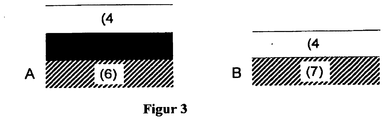
- FIG. 3 shows embodiments of the invention with an arrangement of the material zones one above the other (vertical).
- the reference numeral (4) designates the material zone contacted by the exhaust gas with a sales profile at higher temperatures.
- the reference numerals (5) and (7) refer to downstream of the exhaust contacted material zones with sales profile at lower temperatures, reference numeral (7) is used only for the special case that the downstream contacted material zone represents a catalytically active in the SCR reaction support body.
- Reference numeral (6) denotes an inert support body.
- FIG. 3B Vertical arrangements as in FIG. 3B are suitable whenever used as downstream of the exhaust gas to be contacted material zone (7) full catalysts with sales profile at lower temperatures, which also serve as a supporting body for a further catalytically active coating with sales profile at higher temperatures (4).
- an inert carrier body (6) can first be coated with a catalytically active coating having a sales profile at lower temperatures (5) and the resulting "cryogenic SCR catalyst" as a supporting body for a catalytically active coating, the SCR good at higher temperatures Activity and selectivity shows (4) to be used. This creates the in FIG. 3A illustrated embodiment.
- One way to prevent this is the arrangement of a further coating between the material zones (5) and (4) or (7) and (4), which acts as a diffusion barrier with respect to the transition metal atoms.
- the effect of such a diffusion barrier can, depending on the material used and depending on the cleaning task of a structured catalytic converter on a mechanical or on a based chemical barrier effect. Preference is given to diffusion barriers with chemical barrier effect.
- H-zeolites In a particularly preferred embodiment of the present invention, between the vertically stacked material zones (5) and (4) or (7) and (4) ( FIGS. 3A or 3B) a diffusion barrier with chemical barrier effect, the predominantly non-exchanged zeolites, called H-zeolites, and / or ammonium-exchanged zeolites contains arranged.
- the effect of H zeolites is based on the fact that transition metal atoms, which migrate thermally induced from a catalytically active coating out into the zeolitic barrier layer, are chemically bound in the pores of the zeolite. This is done by an ion exchange in the solid, which leads to the release of the faster migrating, smaller protons.
- the transition metal atoms are chemically bound to the adsorption sites of the protons. Your hike will be stopped for the time being. Only when all proton adsorption sites in the zeolitic barrier layer have been exchanged with the transition metal and an enrichment at the interface to the adjacent catalytically active layer takes place through further migration into the barrier layer and the threshold concentration is exceeded, does the diffusion barrier lose its effectiveness. This point can be prevented by a dimensioning of the diffusion barrier adapted to the concentration of the transition metal atoms in the catalytically active coating.
- transition metal atoms from the adjacent catalytically active coatings migrate into a barrier layer of ammonium-exchanged zeolite, ammonia is released in addition to protons.
- This is initially stored in the cage structure of the zeolite and can be used for the reduction of nitrogen oxides in the selective catalytic reduction.
- both in the cage structure of H-zeolites and in the cage structure of ammonium-exchanged zeolites hydrocarbon molecules from the exhaust gas can be cached. These are then also available as a reducing agent.
- Model gas component Concentration: NO 500 ppm NH 3 425 ppm O 2 5% by volume H 2 O 1.3% by volume N 2 rest
- the space velocity in the model gas tests carried out was 30,000 h -1 .
- FIG. 1 The result of the investigations is in FIG. 1 shown.
- the curves marked ( ⁇ ) show the results for VK1.
- the catalyst reaches a maximum nitrogen oxide conversion of 70% at temperatures between 350 ° C and 500 ° C when freshly prepared. Since at 500 ° C, no degradation of the conversion can be observed, it can be assumed that the conversion level of about 70% can be maintained even at higher temperatures. Below 350 ° C, the conversions increase slowly and almost linearly with temperature. T 50 is 225 ° C. The resulting by over-oxidation of ammonia N 2 O content after catalyst is in the entire temperature window below 10 ppm is thus not relevant for the determination of the sales profile.
- the sales profile typical for VK1 in the sense of this patent specification includes the temperature range of 225 ° C. to> 500 ° C., marked with (
- FIG. 1 The result of the investigations is in FIG. 1 shown.
- the curves marked with ( ⁇ ) show the results for VK2.
- the catalyst reaches in freshly prepared state after passing through the T 50 value at 175 ° C, a maximum nitrogen oxide conversion of 74% at 240 ° C. Above 350 ° C, the observed nitrogen oxide conversions fall significantly and fall below 380 ° C values of 66%. Even at a lower temperature, the N 2 O concentrations resulting from the overoxidation of ammonia rise to more than 25 ppm.
- the sales profile typical for VK2 in the sense of this patent specification encompasses the temperature range of 175 ° C. to 310 ° C. denoted by ( ⁇ ).
- FIG. 1 shows very clearly the typical for conventional SCR catalysts restriction of the work area, the target conflict between the minimum required oxidation force for effective pre-oxidation of NO to NO 2 on the one hand and the maximum usable oxidation force, which is just still allowed to overoxidation of as a reducing agent on the other hand, to prevent ammonia used, on the other hand, comes about.
- a catalytically active coating consisting of two material zones was applied to an inert ceramic honeycomb body.
- the honeycomb body was first provided with a material zone of a copper-exchanged zeolite according to catalyst VK 2 from Comparative Example 2 and calcined for better adhesion of the coating at 500 ° C for a period of 2 hours in air.
- a further material zone consisting of an iron-exchanged zeolite corresponding to VK 1 from Comparative Example 1 was applied.
- two inventive catalysts with vertical material zone arrangement were accordingly FIG.
- the exhaust gas to be purified initially diffuses through the material zone consisting of iron exchanged zeolite, which is characterized by a sales profile at higher temperatures. There the SCR reaction takes place at operating temperatures above 350 ° C. After penetrating this upper material zone, the lower one, the one with copper exchanged zeolite-containing layer reaches, in which optionally unreacted nitrogen oxides react with unreacted ammonia. This occurs especially when the operating temperatures of the catalyst are still below 350 ° C.
- the conversion profile of the two catalysts according to the invention was investigated in the freshly prepared state in a stationary model gas test.
- the selected test conditions corresponded exactly to the conditions listed in Comparative Example 1.
- FIG. 4 shows the result of the investigation.
- Both inventive catalysts have a broader or a larger range of the target working window covering sales profile than the comparative catalysts from Comparative Examples 1 and 2.
- V1 shows a T 50 value of 180 ° C a slightly slower increase in nitrogen oxide conversion in the low temperature range than V2 with T 50 of 160 ° C.
- the maximum conversion is for V1 at 290 ° C with 76%, for V2 at 240 ° C with 78% conversion.
- the resulting upper limits of the conversion range of 68% conversion for V1 and 70% conversion for V2 are 490 ° C (V1) and 425 ° C (V2), respectively.
- An N 2 O content after catalyst of more than 25 ppm is not observed.
- the turnover profile of 180 ° C to 490 ° C which is hatched with (
- the turnover profile of V2 indicated by ( ⁇ ) covers the temperature range 160 ° C to 425 ° C.
- both catalysts according to the invention showed a sales profile which was significantly shifted towards lower temperatures or extended.
- VK2 a significant broadening of the sales profile is achieved.
- V1 achieves a widening of the sales profile in the measured temperature range that is relevant for the application.
- the catalysts according to the invention after hydrothermal aging show considerable losses in the nitrogen oxide conversion, in particular below 350 ° C.
- This behavior is known from conventional SCR catalysts, such as VK1 shows, and represents a general, as yet unsolved problem observed performance decline of the catalysts of the invention, however, is considerably stronger than in conventional catalysts. This is due to negative interactions between the two material zones, presumably an uncontrolled migration of transition-metal atoms, which has a selective-destroying effect. Such an interaction can be considerably minimized by reducing the contact areas between the material zones.
- a horizontal arrangement of the material zones is especially the preferred embodiment of the invention, when the catalysts are to be used at very high temperatures and water vapor contents in the exhaust gas.
Landscapes
- Chemical & Material Sciences (AREA)
- Engineering & Computer Science (AREA)
- Chemical Kinetics & Catalysis (AREA)
- Materials Engineering (AREA)
- Organic Chemistry (AREA)
- Health & Medical Sciences (AREA)
- Combustion & Propulsion (AREA)
- Biomedical Technology (AREA)
- Crystallography & Structural Chemistry (AREA)
- Environmental & Geological Engineering (AREA)
- Analytical Chemistry (AREA)
- General Chemical & Material Sciences (AREA)
- Oil, Petroleum & Natural Gas (AREA)
- Toxicology (AREA)
- Mechanical Engineering (AREA)
- General Engineering & Computer Science (AREA)
- Catalysts (AREA)
- Exhaust Gas Treatment By Means Of Catalyst (AREA)
- Exhaust Gas After Treatment (AREA)
Claims (7)
- Catalyseur SCR structuré destiné à réduire les oxydes d'azote dans les gaz d'échappement pauvres de moteurs à combustion interne en utilisant comme agent de réduction de l'ammoniac ou un composé qui peut être décomposé en ammoniac, le catalyseur étant constitué de l'assemblage de plusieurs zones de matériau catalytiquement actif appliquées sur un corps de support éventuellement inerte sur le plan catalytique et mises en contact successivement avec les gaz d'échappement, les zones de matériau étant disposées les unes au-dessus des autres et la couche supérieure étant la zone de matériau qui entre en premier en contact avec le gaz d'échappement à épurer, et dans lequel les zones de matériau sont caractérisées par différents profils de conversion de la réaction SCR, et où le profil de conversion de la première zone de matériau qui entre en contact avec les gaz d'échappement à épurer atteint des températures plus élevées que le profil de conversion de la zone de matériau entrant en contact avec les gaz d'échappement à épurer qui est placée en aval
caractérisé en ce
que la première zone en contact avec les gaz d'échappement à épurer est constituée d'une zéolithe dont certains ions ont été remplacés par des ions de fer,
et que la zone de matériau mise en contact en aval avec les gaz d'échappement à épurer contient une zéolithe dont certains ions ont été remplacés par des ions de métal de transition, et le métal de transition contenu dans la zéolithe est le cuivre, et
caractérisé en ce
qu'il ne contient aucun métal du groupe du platine et
dans lequel le profil de conversion désigne la fenêtre de température de travail optimale d'un catalyseur SCR à l'état tel qu'il vient d'être fabriqué et ayant une limite de température inférieure et une limite de température supérieure,
dans lequel la limite de température inférieure est la température à laquelle 50 % de la conversion maximale caractéristique du catalyseur peut être obtenue, et la limite de température supérieure est la température à laquelle 90 % de la conversion maximale caractéristique du catalyseur peut être obtenue, dans lequel le profil de conversion est limité lorsque la teneur en N2O mesurée par le catalyseur dépasse un certain seuil critique qui atteint 25 ppm,
dans lequel les profils de conversion de la réaction SCR des zones de matériau sont déterminés dans un essai à l'arrêt sur un système de gaz modèle avec les concentrations de gaz suivantes :Composant de gaz modèle : Concentration NO 500 ppm NH3 425 ppm O2 5 % en vol. H2O 1,3 % en volume, N2 Reste
dans lequel le profil de conversion de la première zone de matériau en contact avec les gaz d'échappement est compris entre 350 °C et 500 °C et le profil de conversion de la zone de matériau en aval en contact avec les gaz d'échappement est compris entre 200 °C et 350 °C. - Catalyseur SCR structuré selon la revendication 1,
caractérisé en ce
que la zone de matériau mise en contact en second lieu avec les gaz d'échappement à épurer est disposée entre la couche supérieure et un corps en nid d'abeilles utilisé comme corps de support. - Catalyseur SCR structuré selon la revendication 1,
caractérisé en ce
que la zone de matériau mise en contact en second lieu avec les gaz d'échappement à épurer est identique à un corps en nid d'abeilles utilisé comme corps de support. - Catalyseur SCR structuré selon les revendications 2 ou 3,
caractérisé en ce
qu'un autre revêtement qui joue le rôle d'une barrière à la diffusion vis-à-vis des atomes de métaux de transition est disposé entre les zones de matériau. - Catalyseur SCR structuré selon la revendication 4,
caractérisé en ce
que le revêtement contient principalement des zéolithes sans remplacement d'ions (zéolithes H), ou des zéolithes dont certains ions ont été remplacés par des ions ammonium ou leurs combinaisons. - Installation d'épuration de gaz d'échappement contenant du catalyseur SCR structuré selon l'une des revendications 1 à 5.
- Utilisation d'un catalyseur SCR structuré selon l'une des revendications 1 à 5 pour éliminer les oxydes d'azote des gaz d'échappement pauvres de moteurs à combustion interne en utilisant comme agent de réduction de l'ammoniac ou un composé qui se décompose en ammoniac.
Priority Applications (1)
| Application Number | Priority Date | Filing Date | Title |
|---|---|---|---|
| EP07764577.8A EP2040834B2 (fr) | 2006-07-08 | 2007-06-06 | Catalyseur scr structuré pour la réduction d'oxydes d'azote dans les gaz d'échappement de moteurs à mélange pauvre utilisant l'ammoniac en tant qu'agent de réduction |
Applications Claiming Priority (4)
| Application Number | Priority Date | Filing Date | Title |
|---|---|---|---|
| DE102006031724A DE102006031724B3 (de) | 2006-07-08 | 2006-07-08 | Strukturierter SCR-Katalysator zur Reduktion von Stickoxiden im Abgas von Magermotoren unter Verwendung von Ammoniak als Reduktionsmittel |
| EP06019975 | 2006-09-25 | ||
| PCT/EP2007/005006 WO2008006427A1 (fr) | 2006-07-08 | 2007-06-06 | Catalyseur scr structuré pour la réduction d'oxydes d'azote dans les gaz d'échappement de moteurs à mélange pauvre au moyen de l'utilisation d'ammoniac en tant qu'agent de réduction |
| EP07764577.8A EP2040834B2 (fr) | 2006-07-08 | 2007-06-06 | Catalyseur scr structuré pour la réduction d'oxydes d'azote dans les gaz d'échappement de moteurs à mélange pauvre utilisant l'ammoniac en tant qu'agent de réduction |
Publications (3)
| Publication Number | Publication Date |
|---|---|
| EP2040834A1 EP2040834A1 (fr) | 2009-04-01 |
| EP2040834B1 EP2040834B1 (fr) | 2012-08-29 |
| EP2040834B2 true EP2040834B2 (fr) | 2019-10-30 |
Family
ID=38362438
Family Applications (1)
| Application Number | Title | Priority Date | Filing Date |
|---|---|---|---|
| EP07764577.8A Active EP2040834B2 (fr) | 2006-07-08 | 2007-06-06 | Catalyseur scr structuré pour la réduction d'oxydes d'azote dans les gaz d'échappement de moteurs à mélange pauvre utilisant l'ammoniac en tant qu'agent de réduction |
Country Status (5)
| Country | Link |
|---|---|
| US (1) | US8568678B2 (fr) |
| EP (1) | EP2040834B2 (fr) |
| JP (1) | JP5345530B2 (fr) |
| KR (1) | KR101362685B1 (fr) |
| WO (1) | WO2008006427A1 (fr) |
Families Citing this family (29)
| Publication number | Priority date | Publication date | Assignee | Title |
|---|---|---|---|---|
| US8389432B2 (en) | 2006-09-25 | 2013-03-05 | Umicore Ag & Co. Kg | Structured automotive catalyst with improved thermal ageing stability |
| US7998423B2 (en) | 2007-02-27 | 2011-08-16 | Basf Corporation | SCR on low thermal mass filter substrates |
| US8636959B2 (en) | 2007-05-09 | 2014-01-28 | N.E. Chemcat Corporation | Selective catalytic reduction type catalyst, and exhaust gas purification equipment and purifying process of exhaust gas using the same |
| JP5110954B2 (ja) | 2007-05-09 | 2012-12-26 | エヌ・イーケムキャット株式会社 | 選択還元型触媒を用いた排気ガス浄化触媒装置並びに排気ガス浄化方法 |
| DE102008008748A1 (de) | 2008-02-12 | 2009-08-13 | Man Nutzfahrzeuge Ag | Vorrichtung zur Verminderung von Dibenzo-Dioxin- und Dibenzo-Furan-Emissionen aus übergangsmetallhaltigen Katalysatoren |
| DE102008009672B4 (de) * | 2008-02-18 | 2016-02-25 | Süd-Chemie Ip Gmbh & Co. Kg | SCR-Katalysator mit Kohlenwasserstoffspeicherfunktion, dessen Verwendung und Abgasreinigungssystem und dessen Verwendung |
| ATE460973T1 (de) * | 2008-04-11 | 2010-04-15 | Umicore Ag & Co Kg | Abgasreinigungssystem zur behandlung von motorenabgasen mittels scr-katalysator |
| JP2010000499A (ja) * | 2008-05-20 | 2010-01-07 | Ibiden Co Ltd | ハニカム構造体 |
| WO2009141886A1 (fr) * | 2008-05-20 | 2009-11-26 | イビデン株式会社 | Structure en nid d'abeille |
| US8524185B2 (en) | 2008-11-03 | 2013-09-03 | Basf Corporation | Integrated SCR and AMOx catalyst systems |
| US10583424B2 (en) | 2008-11-06 | 2020-03-10 | Basf Corporation | Chabazite zeolite catalysts having low silica to alumina ratios |
| WO2011061839A1 (fr) * | 2009-11-19 | 2011-05-26 | イビデン株式会社 | Structure en nid d'abeille et appareil de purification des gaz d'échappement |
| GB2475740B (en) * | 2009-11-30 | 2017-06-07 | Johnson Matthey Plc | Catalysts for treating transient NOx emissions |
| US9120056B2 (en) | 2010-02-16 | 2015-09-01 | Ford Global Technologies, Llc | Catalyst assembly for treating engine exhaust |
| US8617497B2 (en) | 2010-04-20 | 2013-12-31 | Umicore Ag & Co. Kg | Mixed oxide materials for the selective catalytic reduction of nitrogen oxides in exhaust gases |
| JP5002040B2 (ja) * | 2010-07-07 | 2012-08-15 | トヨタ自動車株式会社 | 内燃機関の排気浄化装置 |
| US8304366B2 (en) | 2010-11-24 | 2012-11-06 | Ford Global Technologies, Llc | System for remediating emissions and method of use |
| US8789356B2 (en) * | 2011-07-28 | 2014-07-29 | Johnson Matthey Public Limited Company | Zoned catalytic filters for treatment of exhaust gas |
| RU2651917C2 (ru) | 2012-10-18 | 2018-04-24 | Джонсон Мэтти Паблик Лимитед Компани | Близко размещенная система scr |
| DE102013003112B4 (de) | 2013-02-25 | 2017-06-14 | Umicore Ag & Co. Kg | SCR-Katalysator mit verbessertem NOx-Umsatz |
| KR101542976B1 (ko) | 2013-12-23 | 2015-08-07 | 현대자동차 주식회사 | 선택적 환원 촉매의 반응 모델을 위한 보정 로직을 결정하는 방법, 선택적 환원 촉매의 반응 모델의 파라미터를 보정하는 방법 및 이를 이용한 배기 장치 |
| FR3041032B1 (fr) * | 2015-09-14 | 2017-09-01 | Peugeot Citroen Automobiles Sa | Dispositif de post-traitement des gaz d’echappement d’un moteur a combustion |
| CN106166455B (zh) * | 2016-08-10 | 2020-01-07 | 大唐环境产业集团股份有限公司 | 一种脱硝氨气预处理系统 |
| JP6693406B2 (ja) * | 2016-12-20 | 2020-05-13 | 三菱自動車工業株式会社 | 排気ガス浄化装置 |
| US11229901B2 (en) | 2016-12-20 | 2022-01-25 | Umicore Ag & Co. Kg | SCR catalyst device containing vanadium oxide and molecular sieve containing iron |
| KR20190091362A (ko) | 2016-12-20 | 2019-08-05 | 우미코레 아게 운트 코 카게 | 바나듐 산화물 및 철을 함유하는 분자체를 함유하는 scr 촉매 장치 |
| CN108889297B (zh) * | 2018-07-31 | 2020-12-29 | 包头稀土研究院 | Scr催化剂及其制备方法和应用 |
| CN114870828B (zh) * | 2022-05-20 | 2023-04-25 | 安徽中环环保科技股份有限公司 | 一种蜂巢石载铈复合脱硝剂及其制备方法和应用 |
| KR20250065993A (ko) | 2023-11-06 | 2025-05-13 | 다이텍연구원 | 질소산화물 제거용 촉매 및 그의 제조방법 |
Citations (6)
| Publication number | Priority date | Publication date | Assignee | Title |
|---|---|---|---|---|
| JPH0796183A (ja) † | 1993-09-27 | 1995-04-11 | Honda Motor Co Ltd | Hc浄化部材 |
| US5409671A (en) † | 1991-12-26 | 1995-04-25 | Mazda Motor Corporation | Catalytic converter for treating exhaust gas |
| US20020025905A1 (en) † | 2000-05-10 | 2002-02-28 | Michael Harris | Structured catalysts for selective reduction of nitrogen oxides by ammonia using a compound that can be hydrolyzed to ammonia |
| WO2005082494A1 (fr) † | 2004-02-27 | 2005-09-09 | Tokyo Roki Co. Ltd. | SYSTEME DE CATALYSEur POUR L'ELIMINATION DE L'OXYDE D'AZOTE ET PROCEDE D'ELMINATION DE L'OYDE D'AZOTE |
| WO2006031297A2 (fr) † | 2004-07-27 | 2006-03-23 | The Regents Of The University Of California | Catalyseurs et procede pour la reduction d'oxydes d'azote |
| CA2652837A1 (fr) † | 2006-05-31 | 2007-12-06 | Umicore Ag & Co. Kg | Catalyseur destine a reduire les polluants contenant de l'azote dans des gaz d'echappement de moteurs diesel |
Family Cites Families (16)
| Publication number | Priority date | Publication date | Assignee | Title |
|---|---|---|---|---|
| DE3906136C1 (fr) | 1989-02-28 | 1990-08-09 | Degussa Ag, 6000 Frankfurt, De | |
| US4961917A (en) * | 1989-04-20 | 1990-10-09 | Engelhard Corporation | Method for reduction of nitrogen oxides with ammonia using promoted zeolite catalysts |
| US5024981A (en) | 1989-04-20 | 1991-06-18 | Engelhard Corporation | Staged metal-promoted zeolite catalysts and method for catalytic reduction of nitrogen oxides using the same |
| US5874057A (en) | 1995-07-12 | 1999-02-23 | Engelhard Corporation | Lean NOx catalyst/trap method |
| US6125629A (en) | 1998-11-13 | 2000-10-03 | Engelhard Corporation | Staged reductant injection for improved NOx reduction |
| US6689709B1 (en) | 2000-11-15 | 2004-02-10 | Engelhard Corporation | Hydrothermally stable metal promoted zeolite beta for NOx reduction |
| US6914026B2 (en) | 2001-09-07 | 2005-07-05 | Engelhard Corporation | Hydrothermally stable metal promoted zeolite beta for NOx reduction |
| GB0220645D0 (en) * | 2002-09-05 | 2002-10-16 | Johnson Matthey Plc | Exhaust system for a lean burn ic engine |
| DE10257113A1 (de) * | 2002-12-05 | 2004-06-24 | Emitec Gesellschaft Für Emissionstechnologie Mbh | Partikelfalle mit beschichteter Faserlage |
| DE10335785A1 (de) * | 2003-08-05 | 2005-03-10 | Umicore Ag & Co Kg | Katalysatoranordnung und Verfahren zur Reinigung des Abgases von mager betriebenen Verbrennungsmotoren |
| US7198769B2 (en) * | 2003-12-02 | 2007-04-03 | Cichanowicz J Edward | Multi-stage process for SCR of NOx |
| US7438876B2 (en) * | 2003-12-02 | 2008-10-21 | Cichanowicz J Edward | Multi-stage heat absorbing reactor and process for SCR of NOx and for oxidation of elemental mercury |
| DE10360955A1 (de) | 2003-12-23 | 2005-07-21 | Umicore Ag & Co. Kg | Abgasreinigungsanlage und Verfahren zur Entfernung von Stickoxiden aus dem Abgas von Verbrennungsmotoren mit Hilfe von katalytisch erzeugtem Ammoniak |
| JP2006057578A (ja) * | 2004-08-23 | 2006-03-02 | Hino Motors Ltd | 排気浄化装置 |
| US7481983B2 (en) | 2004-08-23 | 2009-01-27 | Basf Catalysts Llc | Zone coated catalyst to simultaneously reduce NOx and unreacted ammonia |
| KR100917495B1 (ko) * | 2006-11-27 | 2009-09-16 | 나노스텔라 인코포레이티드 | 팔라듐-금을 포함하는 엔진 배기가스 촉매 |
-
2007
- 2007-06-06 EP EP07764577.8A patent/EP2040834B2/fr active Active
- 2007-06-06 US US12/307,696 patent/US8568678B2/en active Active
- 2007-06-06 JP JP2009518729A patent/JP5345530B2/ja active Active
- 2007-06-06 KR KR1020097000329A patent/KR101362685B1/ko active Active
- 2007-06-06 WO PCT/EP2007/005006 patent/WO2008006427A1/fr not_active Ceased
Patent Citations (8)
| Publication number | Priority date | Publication date | Assignee | Title |
|---|---|---|---|---|
| US5409671A (en) † | 1991-12-26 | 1995-04-25 | Mazda Motor Corporation | Catalytic converter for treating exhaust gas |
| JPH0796183A (ja) † | 1993-09-27 | 1995-04-11 | Honda Motor Co Ltd | Hc浄化部材 |
| US20020025905A1 (en) † | 2000-05-10 | 2002-02-28 | Michael Harris | Structured catalysts for selective reduction of nitrogen oxides by ammonia using a compound that can be hydrolyzed to ammonia |
| WO2005082494A1 (fr) † | 2004-02-27 | 2005-09-09 | Tokyo Roki Co. Ltd. | SYSTEME DE CATALYSEur POUR L'ELIMINATION DE L'OXYDE D'AZOTE ET PROCEDE D'ELMINATION DE L'OYDE D'AZOTE |
| EP1736232A1 (fr) † | 2004-02-27 | 2006-12-27 | Tokyo Roki Co. Ltd. | Systeme de catalyseur pour l' elimination de l'oxyde d'azote et procede d'elmination de l' oxyde d' azote |
| WO2006031297A2 (fr) † | 2004-07-27 | 2006-03-23 | The Regents Of The University Of California | Catalyseurs et procede pour la reduction d'oxydes d'azote |
| CA2652837A1 (fr) † | 2006-05-31 | 2007-12-06 | Umicore Ag & Co. Kg | Catalyseur destine a reduire les polluants contenant de l'azote dans des gaz d'echappement de moteurs diesel |
| WO2007137675A1 (fr) † | 2006-05-31 | 2007-12-06 | Umicore Ag & Co. Kg | Catalyseur destiné à réduire les polluants contenant de l'azote dans des gaz d'échappement de moteurs diesel |
Non-Patent Citations (2)
| Title |
|---|
| BRISCOE N.A. ET AL: "Some Aspects of the Synthesis, Characterisation and Properties of Zeolite Nu-2", STUDIES IN SURFACE SCIENCE AND CATALYSIS, vol. 49, 1989, pages 151 - 160 † |
| LU GANG ET AL: "Low temperature selective oxidation of ammonia to nitrogen on silver-based catalysts", APPLIED CATALYSIS. B, ENVIRONMENTAL, vol. 40, no. 2, 1 January 2003 (2003-01-01), pages 101 - 110, XP055203542, DOI: 10.1016/S0926-3373(02)00129-7 † |
Also Published As
| Publication number | Publication date |
|---|---|
| KR101362685B1 (ko) | 2014-02-13 |
| JP5345530B2 (ja) | 2013-11-20 |
| EP2040834B1 (fr) | 2012-08-29 |
| US8568678B2 (en) | 2013-10-29 |
| EP2040834A1 (fr) | 2009-04-01 |
| US20100209327A1 (en) | 2010-08-19 |
| JP2009542435A (ja) | 2009-12-03 |
| WO2008006427A1 (fr) | 2008-01-17 |
| KR20090027726A (ko) | 2009-03-17 |
Similar Documents
| Publication | Publication Date | Title |
|---|---|---|
| EP2040834B2 (fr) | Catalyseur scr structuré pour la réduction d'oxydes d'azote dans les gaz d'échappement de moteurs à mélange pauvre utilisant l'ammoniac en tant qu'agent de réduction | |
| EP2116293B1 (fr) | Système de nettoyage de gaz d'échappement destiné au traitement de gaz d'échappement de moteur à l'aide d'un catalyseur SCR | |
| EP2616647B1 (fr) | Catalyseur pour éliminer les oxydes d'azote des gaz d'échappement de moteurs diesels | |
| EP1961933B1 (fr) | Filtre à particule de diesel activé de manière catalytique et doté d'une action de blocage à l'ammoniac | |
| EP2091635B1 (fr) | Catalyseur sans vanadium pour la réduction sélective et procède de son production | |
| EP0945165B1 (fr) | Procédé pour éliminer d'oxydes de soufre de gaz d'échappement d'un moteur à combustion interne | |
| EP2029260B1 (fr) | Catalyseur destiné à réduire les polluants contenant de l'azote dans des gaz d'échappement de moteurs diesel | |
| EP2326416B1 (fr) | Catalyseur accumulateur de nox destiné à être placé à proximité du moteur dans un véhicule automobile | |
| DE69519115T2 (de) | Katalysator und Verfahren zur Reinigung von Abgasen | |
| DE60004515T2 (de) | Reinigungszusammensetzung für nox enthaltende abgase einer brennkraftmaschine | |
| EP2560755A1 (fr) | Nouveaux matériaux d'oxyde mixte pour la réduction catalytique sélective d'oxydes d'azote dans des gaz d'échappement | |
| DE112014000481T5 (de) | Abgasreinigungskatalysator und Herstellungsverfahren dafür | |
| EP1316354A1 (fr) | Catalyseur pour la réduction d'oxydes d'azote dans le gaz d'échappement de moteurs à mélange pauvre | |
| EP3498993A1 (fr) | Combinaison d'un scr à base de zéolite avec un scr à base de manganèse en dérivation | |
| DE19847008A1 (de) | Stickoxid-Speicherkatalysator | |
| EP1264628A1 (fr) | Catalyseur Redox pour la réduction catalytique sélective des oxydes d'azote contenus dans les gaz d'échapement des moteurs Diesel au moyen d'ammoniaque et procédé pour le préparer | |
| EP2640513A1 (fr) | Catalyseur destiné à supprimer les oxydes d'azote contenus dans les gaz d'échappement de moteurs diesel | |
| DE102011012799A1 (de) | Katalysator zur Entfernung von Stickoxiden aus dem Abgas von Dieselmotoren | |
| DE69932387T2 (de) | Stickoxidfallenkatalysator für Verbrennungskraftmaschinen mit Magergemischverbrennung | |
| EP3558494A1 (fr) | Dispositif de catalyseur pour réduction catalytique (scr) contenant de l'oxyde de vanadium et un tamis moléculaire renfermant du fer | |
| EP3623047B1 (fr) | Catalyseur de réduction d'oxydes d'azote | |
| DE10360955A1 (de) | Abgasreinigungsanlage und Verfahren zur Entfernung von Stickoxiden aus dem Abgas von Verbrennungsmotoren mit Hilfe von katalytisch erzeugtem Ammoniak | |
| DE102006031724B3 (de) | Strukturierter SCR-Katalysator zur Reduktion von Stickoxiden im Abgas von Magermotoren unter Verwendung von Ammoniak als Reduktionsmittel | |
| EP3695902A1 (fr) | Catalyseur destiné à la réduction d'oxydes d'azote | |
| DE102014222624A1 (de) | Abgasreinigungskatalysator und dessen Herstellungsmethode |
Legal Events
| Date | Code | Title | Description |
|---|---|---|---|
| PUAI | Public reference made under article 153(3) epc to a published international application that has entered the european phase |
Free format text: ORIGINAL CODE: 0009012 |
|
| 17P | Request for examination filed |
Effective date: 20081210 |
|
| AK | Designated contracting states |
Kind code of ref document: A1 Designated state(s): AT BE BG CH CY CZ DE DK EE ES FI FR GB GR HU IE IS IT LI LT LU LV MC MT NL PL PT RO SE SI SK TR |
|
| AX | Request for extension of the european patent |
Extension state: AL BA HR MK RS |
|
| RIN1 | Information on inventor provided before grant (corrected) |
Inventor name: SCHNEIDER, WOLFGANG Inventor name: SESSELMANN, RALF Inventor name: MUSSMANN, LOTHAR Inventor name: ADELMANN, KATJA Inventor name: SOEGER, NICOLA |
|
| 17Q | First examination report despatched |
Effective date: 20090807 |
|
| GRAP | Despatch of communication of intention to grant a patent |
Free format text: ORIGINAL CODE: EPIDOSNIGR1 |
|
| DAX | Request for extension of the european patent (deleted) | ||
| GRAS | Grant fee paid |
Free format text: ORIGINAL CODE: EPIDOSNIGR3 |
|
| GRAA | (expected) grant |
Free format text: ORIGINAL CODE: 0009210 |
|
| AK | Designated contracting states |
Kind code of ref document: B1 Designated state(s): AT BE BG CH CY CZ DE DK EE ES FI FR GB GR HU IE IS IT LI LT LU LV MC MT NL PL PT RO SE SI SK TR |
|
| REG | Reference to a national code |
Ref country code: GB Ref legal event code: FG4D Free format text: NOT ENGLISH |
|
| RIN1 | Information on inventor provided before grant (corrected) |
Inventor name: MUSSMANN, LOTHAR Inventor name: SOEGER, NICOLA Inventor name: SCHNEIDER, WOLFGANG Inventor name: ADELMANN, KATJA Inventor name: SESSELMANN, RALF |
|
| REG | Reference to a national code |
Ref country code: CH Ref legal event code: EP |
|
| REG | Reference to a national code |
Ref country code: AT Ref legal event code: REF Ref document number: 572764 Country of ref document: AT Kind code of ref document: T Effective date: 20120915 |
|
| REG | Reference to a national code |
Ref country code: IE Ref legal event code: FG4D Free format text: LANGUAGE OF EP DOCUMENT: GERMAN |
|
| REG | Reference to a national code |
Ref country code: DE Ref legal event code: R096 Ref document number: 502007010464 Country of ref document: DE Effective date: 20121025 |
|
| REG | Reference to a national code |
Ref country code: NL Ref legal event code: VDEP Effective date: 20120829 |
|
| REG | Reference to a national code |
Ref country code: LT Ref legal event code: MG4D Effective date: 20120822 |
|
| PG25 | Lapsed in a contracting state [announced via postgrant information from national office to epo] |
Ref country code: CY Free format text: LAPSE BECAUSE OF FAILURE TO SUBMIT A TRANSLATION OF THE DESCRIPTION OR TO PAY THE FEE WITHIN THE PRESCRIBED TIME-LIMIT Effective date: 20120829 Ref country code: FI Free format text: LAPSE BECAUSE OF FAILURE TO SUBMIT A TRANSLATION OF THE DESCRIPTION OR TO PAY THE FEE WITHIN THE PRESCRIBED TIME-LIMIT Effective date: 20120829 Ref country code: LT Free format text: LAPSE BECAUSE OF FAILURE TO SUBMIT A TRANSLATION OF THE DESCRIPTION OR TO PAY THE FEE WITHIN THE PRESCRIBED TIME-LIMIT Effective date: 20120829 Ref country code: IS Free format text: LAPSE BECAUSE OF FAILURE TO SUBMIT A TRANSLATION OF THE DESCRIPTION OR TO PAY THE FEE WITHIN THE PRESCRIBED TIME-LIMIT Effective date: 20121229 |
|
| PG25 | Lapsed in a contracting state [announced via postgrant information from national office to epo] |
Ref country code: GR Free format text: LAPSE BECAUSE OF FAILURE TO SUBMIT A TRANSLATION OF THE DESCRIPTION OR TO PAY THE FEE WITHIN THE PRESCRIBED TIME-LIMIT Effective date: 20121130 Ref country code: SE Free format text: LAPSE BECAUSE OF FAILURE TO SUBMIT A TRANSLATION OF THE DESCRIPTION OR TO PAY THE FEE WITHIN THE PRESCRIBED TIME-LIMIT Effective date: 20120829 Ref country code: PT Free format text: LAPSE BECAUSE OF FAILURE TO SUBMIT A TRANSLATION OF THE DESCRIPTION OR TO PAY THE FEE WITHIN THE PRESCRIBED TIME-LIMIT Effective date: 20121231 Ref country code: SI Free format text: LAPSE BECAUSE OF FAILURE TO SUBMIT A TRANSLATION OF THE DESCRIPTION OR TO PAY THE FEE WITHIN THE PRESCRIBED TIME-LIMIT Effective date: 20120829 Ref country code: LV Free format text: LAPSE BECAUSE OF FAILURE TO SUBMIT A TRANSLATION OF THE DESCRIPTION OR TO PAY THE FEE WITHIN THE PRESCRIBED TIME-LIMIT Effective date: 20120829 |
|
| PG25 | Lapsed in a contracting state [announced via postgrant information from national office to epo] |
Ref country code: DK Free format text: LAPSE BECAUSE OF FAILURE TO SUBMIT A TRANSLATION OF THE DESCRIPTION OR TO PAY THE FEE WITHIN THE PRESCRIBED TIME-LIMIT Effective date: 20120829 Ref country code: CZ Free format text: LAPSE BECAUSE OF FAILURE TO SUBMIT A TRANSLATION OF THE DESCRIPTION OR TO PAY THE FEE WITHIN THE PRESCRIBED TIME-LIMIT Effective date: 20120829 Ref country code: NL Free format text: LAPSE BECAUSE OF FAILURE TO SUBMIT A TRANSLATION OF THE DESCRIPTION OR TO PAY THE FEE WITHIN THE PRESCRIBED TIME-LIMIT Effective date: 20120829 Ref country code: EE Free format text: LAPSE BECAUSE OF FAILURE TO SUBMIT A TRANSLATION OF THE DESCRIPTION OR TO PAY THE FEE WITHIN THE PRESCRIBED TIME-LIMIT Effective date: 20120829 Ref country code: ES Free format text: LAPSE BECAUSE OF FAILURE TO SUBMIT A TRANSLATION OF THE DESCRIPTION OR TO PAY THE FEE WITHIN THE PRESCRIBED TIME-LIMIT Effective date: 20121210 Ref country code: RO Free format text: LAPSE BECAUSE OF FAILURE TO SUBMIT A TRANSLATION OF THE DESCRIPTION OR TO PAY THE FEE WITHIN THE PRESCRIBED TIME-LIMIT Effective date: 20120829 |
|
| PG25 | Lapsed in a contracting state [announced via postgrant information from national office to epo] |
Ref country code: PL Free format text: LAPSE BECAUSE OF FAILURE TO SUBMIT A TRANSLATION OF THE DESCRIPTION OR TO PAY THE FEE WITHIN THE PRESCRIBED TIME-LIMIT Effective date: 20120829 Ref country code: SK Free format text: LAPSE BECAUSE OF FAILURE TO SUBMIT A TRANSLATION OF THE DESCRIPTION OR TO PAY THE FEE WITHIN THE PRESCRIBED TIME-LIMIT Effective date: 20120829 |
|
| PLBI | Opposition filed |
Free format text: ORIGINAL CODE: 0009260 |
|
| PLAX | Notice of opposition and request to file observation + time limit sent |
Free format text: ORIGINAL CODE: EPIDOSNOBS2 |
|
| 26 | Opposition filed |
Opponent name: JOHNSON MATTHEY PUBLIC LIMITED COMPANY Effective date: 20130529 |
|
| PG25 | Lapsed in a contracting state [announced via postgrant information from national office to epo] |
Ref country code: BG Free format text: LAPSE BECAUSE OF FAILURE TO SUBMIT A TRANSLATION OF THE DESCRIPTION OR TO PAY THE FEE WITHIN THE PRESCRIBED TIME-LIMIT Effective date: 20121129 |
|
| REG | Reference to a national code |
Ref country code: DE Ref legal event code: R026 Ref document number: 502007010464 Country of ref document: DE Effective date: 20130529 |
|
| PLAF | Information modified related to communication of a notice of opposition and request to file observations + time limit |
Free format text: ORIGINAL CODE: EPIDOSCOBS2 |
|
| BERE | Be: lapsed |
Owner name: UMICORE A.G. & CO. KG Effective date: 20130630 |
|
| PLBB | Reply of patent proprietor to notice(s) of opposition received |
Free format text: ORIGINAL CODE: EPIDOSNOBS3 |
|
| PG25 | Lapsed in a contracting state [announced via postgrant information from national office to epo] |
Ref country code: MC Free format text: LAPSE BECAUSE OF FAILURE TO SUBMIT A TRANSLATION OF THE DESCRIPTION OR TO PAY THE FEE WITHIN THE PRESCRIBED TIME-LIMIT Effective date: 20120829 |
|
| REG | Reference to a national code |
Ref country code: CH Ref legal event code: PL |
|
| REG | Reference to a national code |
Ref country code: IE Ref legal event code: MM4A |
|
| PG25 | Lapsed in a contracting state [announced via postgrant information from national office to epo] |
Ref country code: BE Free format text: LAPSE BECAUSE OF NON-PAYMENT OF DUE FEES Effective date: 20130630 |
|
| PG25 | Lapsed in a contracting state [announced via postgrant information from national office to epo] |
Ref country code: CH Free format text: LAPSE BECAUSE OF NON-PAYMENT OF DUE FEES Effective date: 20130630 Ref country code: IE Free format text: LAPSE BECAUSE OF NON-PAYMENT OF DUE FEES Effective date: 20130606 Ref country code: LI Free format text: LAPSE BECAUSE OF NON-PAYMENT OF DUE FEES Effective date: 20130630 |
|
| REG | Reference to a national code |
Ref country code: AT Ref legal event code: MM01 Ref document number: 572764 Country of ref document: AT Kind code of ref document: T Effective date: 20130606 |
|
| PG25 | Lapsed in a contracting state [announced via postgrant information from national office to epo] |
Ref country code: AT Free format text: LAPSE BECAUSE OF NON-PAYMENT OF DUE FEES Effective date: 20130606 |
|
| PG25 | Lapsed in a contracting state [announced via postgrant information from national office to epo] |
Ref country code: MT Free format text: LAPSE BECAUSE OF FAILURE TO SUBMIT A TRANSLATION OF THE DESCRIPTION OR TO PAY THE FEE WITHIN THE PRESCRIBED TIME-LIMIT Effective date: 20120829 |
|
| PG25 | Lapsed in a contracting state [announced via postgrant information from national office to epo] |
Ref country code: TR Free format text: LAPSE BECAUSE OF FAILURE TO SUBMIT A TRANSLATION OF THE DESCRIPTION OR TO PAY THE FEE WITHIN THE PRESCRIBED TIME-LIMIT Effective date: 20120829 |
|
| PG25 | Lapsed in a contracting state [announced via postgrant information from national office to epo] |
Ref country code: HU Free format text: LAPSE BECAUSE OF FAILURE TO SUBMIT A TRANSLATION OF THE DESCRIPTION OR TO PAY THE FEE WITHIN THE PRESCRIBED TIME-LIMIT; INVALID AB INITIO Effective date: 20070606 Ref country code: LU Free format text: LAPSE BECAUSE OF NON-PAYMENT OF DUE FEES Effective date: 20130606 |
|
| RDAF | Communication despatched that patent is revoked |
Free format text: ORIGINAL CODE: EPIDOSNREV1 |
|
| APBM | Appeal reference recorded |
Free format text: ORIGINAL CODE: EPIDOSNREFNO |
|
| APBP | Date of receipt of notice of appeal recorded |
Free format text: ORIGINAL CODE: EPIDOSNNOA2O |
|
| APAH | Appeal reference modified |
Free format text: ORIGINAL CODE: EPIDOSCREFNO |
|
| APBQ | Date of receipt of statement of grounds of appeal recorded |
Free format text: ORIGINAL CODE: EPIDOSNNOA3O |
|
| REG | Reference to a national code |
Ref country code: FR Ref legal event code: PLFP Year of fee payment: 10 |
|
| REG | Reference to a national code |
Ref country code: FR Ref legal event code: PLFP Year of fee payment: 11 |
|
| APBC | Information on closure of appeal procedure deleted |
Free format text: ORIGINAL CODE: EPIDOSDNOA9O |
|
| APBU | Appeal procedure closed |
Free format text: ORIGINAL CODE: EPIDOSNNOA9O |
|
| REG | Reference to a national code |
Ref country code: FR Ref legal event code: PLFP Year of fee payment: 12 |
|
| APBU | Appeal procedure closed |
Free format text: ORIGINAL CODE: EPIDOSNNOA9O |
|
| PLBP | Opposition withdrawn |
Free format text: ORIGINAL CODE: 0009264 |
|
| PUAH | Patent maintained in amended form |
Free format text: ORIGINAL CODE: 0009272 |
|
| STAA | Information on the status of an ep patent application or granted ep patent |
Free format text: STATUS: PATENT MAINTAINED AS AMENDED |
|
| 27A | Patent maintained in amended form |
Effective date: 20191030 |
|
| AK | Designated contracting states |
Kind code of ref document: B2 Designated state(s): AT BE BG CH CY CZ DE DK EE ES FI FR GB GR HU IE IS IT LI LT LU LV MC MT NL PL PT RO SE SI SK TR |
|
| REG | Reference to a national code |
Ref country code: DE Ref legal event code: R102 Ref document number: 502007010464 Country of ref document: DE |
|
| REG | Reference to a national code |
Ref country code: DE Ref legal event code: R084 Ref document number: 502007010464 Country of ref document: DE |
|
| REG | Reference to a national code |
Ref country code: FR Ref legal event code: PLFP Year of fee payment: 17 |
|
| P01 | Opt-out of the competence of the unified patent court (upc) registered |
Effective date: 20230602 |
|
| PGFP | Annual fee paid to national office [announced via postgrant information from national office to epo] |
Ref country code: DE Payment date: 20250402 Year of fee payment: 19 |
|
| PGFP | Annual fee paid to national office [announced via postgrant information from national office to epo] |
Ref country code: GB Payment date: 20250401 Year of fee payment: 19 |
|
| PGFP | Annual fee paid to national office [announced via postgrant information from national office to epo] |
Ref country code: IT Payment date: 20250522 Year of fee payment: 19 |
|
| PGFP | Annual fee paid to national office [announced via postgrant information from national office to epo] |
Ref country code: FR Payment date: 20250401 Year of fee payment: 19 |