EP2040850B1 - Dispositif comportant un système de récipients pour un fluide corporel - Google Patents
Dispositif comportant un système de récipients pour un fluide corporel Download PDFInfo
- Publication number
- EP2040850B1 EP2040850B1 EP07768912.3A EP07768912A EP2040850B1 EP 2040850 B1 EP2040850 B1 EP 2040850B1 EP 07768912 A EP07768912 A EP 07768912A EP 2040850 B1 EP2040850 B1 EP 2040850B1
- Authority
- EP
- European Patent Office
- Prior art keywords
- container
- widened portion
- centrifuge
- fluid
- blood
- Prior art date
- Legal status (The legal status is an assumption and is not a legal conclusion. Google has not performed a legal analysis and makes no representation as to the accuracy of the status listed.)
- Active
Links
Images
Classifications
-
- B—PERFORMING OPERATIONS; TRANSPORTING
- B04—CENTRIFUGAL APPARATUS OR MACHINES FOR CARRYING-OUT PHYSICAL OR CHEMICAL PROCESSES
- B04B—CENTRIFUGES
- B04B5/00—Other centrifuges
- B04B5/04—Radial chamber apparatus for separating predominantly liquid mixtures, e.g. butyrometers
- B04B5/0407—Radial chamber apparatus for separating predominantly liquid mixtures, e.g. butyrometers for liquids contained in receptacles
- B04B5/0428—Radial chamber apparatus for separating predominantly liquid mixtures, e.g. butyrometers for liquids contained in receptacles with flexible receptacles
-
- A—HUMAN NECESSITIES
- A61—MEDICAL OR VETERINARY SCIENCE; HYGIENE
- A61M—DEVICES FOR INTRODUCING MEDIA INTO, OR ONTO, THE BODY; DEVICES FOR TRANSDUCING BODY MEDIA OR FOR TAKING MEDIA FROM THE BODY; DEVICES FOR PRODUCING OR ENDING SLEEP OR STUPOR
- A61M1/00—Suction or pumping devices for medical purposes; Devices for carrying-off, for treatment of, or for carrying-over, body-liquids; Drainage systems
- A61M1/02—Blood transfusion apparatus
- A61M1/0209—Multiple bag systems for separating or storing blood components
-
- A—HUMAN NECESSITIES
- A61—MEDICAL OR VETERINARY SCIENCE; HYGIENE
- A61M—DEVICES FOR INTRODUCING MEDIA INTO, OR ONTO, THE BODY; DEVICES FOR TRANSDUCING BODY MEDIA OR FOR TAKING MEDIA FROM THE BODY; DEVICES FOR PRODUCING OR ENDING SLEEP OR STUPOR
- A61M1/00—Suction or pumping devices for medical purposes; Devices for carrying-off, for treatment of, or for carrying-over, body-liquids; Drainage systems
- A61M1/02—Blood transfusion apparatus
- A61M1/029—Separating blood components present in distinct layers in a container, not otherwise provided for
-
- A—HUMAN NECESSITIES
- A61—MEDICAL OR VETERINARY SCIENCE; HYGIENE
- A61M—DEVICES FOR INTRODUCING MEDIA INTO, OR ONTO, THE BODY; DEVICES FOR TRANSDUCING BODY MEDIA OR FOR TAKING MEDIA FROM THE BODY; DEVICES FOR PRODUCING OR ENDING SLEEP OR STUPOR
- A61M1/00—Suction or pumping devices for medical purposes; Devices for carrying-off, for treatment of, or for carrying-over, body-liquids; Drainage systems
- A61M1/36—Other treatment of blood in a by-pass of the natural circulatory system, e.g. temperature adaptation, irradiation ; Extra-corporeal blood circuits
- A61M1/3693—Other treatment of blood in a by-pass of the natural circulatory system, e.g. temperature adaptation, irradiation ; Extra-corporeal blood circuits using separation based on different densities of components, e.g. centrifuging
-
- A—HUMAN NECESSITIES
- A61—MEDICAL OR VETERINARY SCIENCE; HYGIENE
- A61M—DEVICES FOR INTRODUCING MEDIA INTO, OR ONTO, THE BODY; DEVICES FOR TRANSDUCING BODY MEDIA OR FOR TAKING MEDIA FROM THE BODY; DEVICES FOR PRODUCING OR ENDING SLEEP OR STUPOR
- A61M1/00—Suction or pumping devices for medical purposes; Devices for carrying-off, for treatment of, or for carrying-over, body-liquids; Drainage systems
- A61M1/36—Other treatment of blood in a by-pass of the natural circulatory system, e.g. temperature adaptation, irradiation ; Extra-corporeal blood circuits
- A61M1/3693—Other treatment of blood in a by-pass of the natural circulatory system, e.g. temperature adaptation, irradiation ; Extra-corporeal blood circuits using separation based on different densities of components, e.g. centrifuging
- A61M1/3698—Expressing processed fluid out from the turning rotor using another fluid compressing the treatment chamber; Variable volume rotors
-
- A—HUMAN NECESSITIES
- A61—MEDICAL OR VETERINARY SCIENCE; HYGIENE
- A61P—SPECIFIC THERAPEUTIC ACTIVITY OF CHEMICAL COMPOUNDS OR MEDICINAL PREPARATIONS
- A61P7/00—Drugs for disorders of the blood or the extracellular fluid
- A61P7/08—Plasma substitutes; Perfusion solutions; Dialytics or haemodialytics; Drugs for electrolytic or acid-base disorders, e.g. hypovolemic shock
-
- B—PERFORMING OPERATIONS; TRANSPORTING
- B04—CENTRIFUGAL APPARATUS OR MACHINES FOR CARRYING-OUT PHYSICAL OR CHEMICAL PROCESSES
- B04B—CENTRIFUGES
- B04B9/00—Drives specially designed for centrifuges; Arrangement or disposition of transmission gearing; Suspending or balancing rotary bowls
- B04B9/10—Control of the drive; Speed regulating
-
- B—PERFORMING OPERATIONS; TRANSPORTING
- B04—CENTRIFUGAL APPARATUS OR MACHINES FOR CARRYING-OUT PHYSICAL OR CHEMICAL PROCESSES
- B04B—CENTRIFUGES
- B04B13/00—Control arrangements specially designed for centrifuges; Program control of centrifuges
- B04B2013/006—Interface detection or monitoring of separated components
Definitions
- the invention relates to a device for separating a bodily fluid into fractions under centrifugal force, which device comprises a flexible container system, this container system comprising at least a first container for the fluid to be separated and a second container for a separated fraction, wherein the containers are mutually connected using a connecting conduit for a fluid.
- the invention also relates to a method for separating blood platelet concentrate into fractions under centrifugal force.
- Human blood substantially comprises four components, i.e. blood plasma, blood platelets (thrombocytes), white blood cells (leukocytes) and red blood cells.
- the white blood cells and the blood platelets are together also referred to as buffy coat, and usually form about 1% of the blood.
- the red blood cells form about 45% of the blood, while the remaining part, i.e. about 54%, is formed by blood plasma.
- the demand for the different blood constituents in the purest possible form is considerable and continues to increase. Different methods are known from the prior art for producing blood products by separating the different constituents from each other.
- a known method for separating whole blood into different fractions such as red cells, blood platelets and plasma comprises of applying centrifugal force.
- a plastic container with a unit of whole blood of for instance between 400-550 ml is placed in a centrifuge.
- the container with the different layers is subsequently removed carefully from the centrifuge and placed in a pressing device with which the layers are pressed to different containers.
- a pressing device with which the layers are pressed to different containers.
- the above described method can also be applied directly in the case of a blood donor, wherein blood is taken and then separated.
- the desired blood products are pressed and collected and the other constituents are returned directly to the donor.
- This method is known to the skilled person under the name apheresis.
- they In order to increase the quality of the thus obtained blood products to the desired level, they have to be filtered in order to thereby reduce particularly the leukocyte content.
- blood products with a reduced content of leukocytes have a higher value, and therefore also a higher price.
- Particularly blood platelet concentrates obtained in accordance with the above method have too high a leukocyte content. An additional step is necessary in order to make a blood platelet concentrate from whole blood.
- a number of blood platelet concentrates are generally combined and separately centrifuged once again so that at least part of the leukocytes are separated. After centrifuging, the blood platelet concentrate freed of leukocytes is pressed to a separate container via a conduit. After this step the blood platelet concentrate is then filtered once again in order to comply with the current standards for blood products, wherein the limit for low-leukocyte blood components is generally set at a leukocyte content lower than 1 million leukocytes per therapeutic unit. It is however generally known from the literature that contact of blood constituents with filter material of leukocyte filters has an adverse effect on the quality of the relevant blood constituents. Enzymes and cytokines can for instance thus be released from the leukocytes, which is undesirable.
- NL 1006731 C2 describes a device for separating a bodily fluid into fractions under centrifugal force.
- the device comprises a flexible container system with containers which are mutually connected using connecting conduits. While a reasonable degree of separation can be achieved with the device described in NL 1006731 C2 , this is not however at the desired level.
- the present invention has for its object to provide a device and method for separating a bodily fluid, in particular blood platelet concentrate, into fractions under centrifugal force, wherein a high-quality blood product is obtained.
- the present invention has the particular object of providing a device and method for separating blood platelet concentrate into fractions under centrifugal force wherein a low-leukocyte blood platelet concentrate is obtained.
- the device comprises a flexible container system, which container system comprises at least a first container for the fluid to be separated, and a second container for a separated fraction, wherein the containers are mutually connected using a connecting conduit for a fluid, wherein a widened portion is arranged in the connecting conduit between the first and second container, wherein during use a detectable separating layer is created in the widened portion characterised by the features of the characterizing portion of claim 1.
- the widened portion provides, among other things, for a better detection of the different separated components and enables a more precise separation and pressing of the components.
- the widened portion in the conduit in the centrifugal force field between the first container (where the first separation takes place) and the second container it becomes possible for instance to prepare platelet concentrates with a remaining leukocyte content of less than 5 million per unit, preferably less than 3 million per unit, most preferably less than 1 million per unit.
- a device for separating whole blood into fractions under centrifugal force is known from US 2003/195104 A1 wherein the containers are mutually connected using connecting conduits in which a widened portion can be arranged.
- the widened portion acts as collecting container for buffy coat, and not as a means for obtaining a more precise second separation between bodily fluid components, and in particular between blood platelets and leukocytes, during centrifugation.
- the device and method according to the invention are particularly suitable for the preparation of blood platelet concentrates, and particularly those with a reduced leukocyte content.
- the widened portion in the conduit system can take diverse forms. It is thus possible for the widened portion to be trapezium-shaped, cylindrical, rectangular or to take any other suitable form. The only limitation set on the form thereof is that it must result in a decrease in the average flow speed of the fluid relative to the average flow speed in the conduit.
- the widened portion is connected to the first container via an incoming conduit and to the second container via an outgoing conduit.
- the incoming conduit is preferably positioned at the largest radius of the centrifuge, while the outgoing conduit is preferably positioned at a smaller radius.
- the widened portion can be both flexible and rigid.
- the widened portion can thus be manufactured for instance from an injection-moulded plastic, wherein the widened portion is preferably relatively flat.
- the widened portion is preferably also transparent enough to enable detection of the separating layer, for instance by optical means.
- a preferred embodiment of the device according to the invention is characterized in that the device is provided with means using which the connecting conduit between the first container and the widened portion and/or between the widened portion and the second container can be blocked and unblocked.
- the means with which the connecting conduit between the containers can be blocked and unblocked preferably comprise clamping means.
- Such clamping means can pinch shut (block) or leave clear (unblock) the connecting conduit between the respective containers depending on the situation desired.
- the clamping means can be coupled to the centrifuge device, while the device according to the present invention is provided with members, for instance openings, which can co-act with the clamping means and thus contribute toward (un)blocking of the connecting members.
- the blocking means in the device can provide for a blocking (closure) or unblocking (opening) of the connecting conduit between the containers.
- the device can be placed, together with the container system coupled thereto, in a space suitable for the purpose in a centrifuge device.
- a plurality of devices are preferably processed simultaneously in the centrifuge. Is also possible to process only one device in the centrifuge, for instance when an annular container system is applied as first container.
- An example of such a centrifuge device is that of the Orbisac® type.
- the blocking means can in the first instance close the connecting conduit between the first container and the widened portion, and the widened portion and the second container, until a separation of blood constituents has taken place in the first container.
- the connecting conduit between the two containers can then be unblocked so that one of the blood constituent layers can flow out of the first container, via the widened portion, into the second container.
- the widened portion herein provides for a more sharply defined separating layer, and therefore a better separation.
- the connecting conduit between the first container and the widened portion and between the widened portion and the second container can be closed using one or more blocking means.
- the device according to the invention comprises pressing means, using which at least the first container can be subjected to a pressure exerted from outside the relevant container. It is also possible to provide the device with a pump device with which the fluid is pumped from the first container to the second container counter to the centrifugal direction.
- the device comprises detection means for detecting the position of the separated fractions in the widened portion.
- Use of the widened portion creates a more sharply defined separating layer, the position of which can be detected in simpler and more accurate manner by the detection means.
- the device comprises a row of detection means for detecting the position and the progress of the separated fractions in the widened portion, and in particular of the separating layer.
- the row of detection means is disposed for this purpose in the direction of flow of the bodily fluid, preferably along the whole or partial length of the widened portion, so that the progress of the separating layer can be followed.
- the detection means comprise a light source disposed on one side of the widened portion and a row of light-sensitive sensors which are disposed on the other side of the widened portion and which can measure the intensity of the light scattered by the fluid present in the widened portion.
- the light-sensitive detectors are preferably set here such that they generate a signal to actuating means present in the device when a determined blood component not to be collected in the second container reaches the outlet conduit of the widened portion.
- the actuating means then ensure that one or more blocking means are actuated, for instance activated, whereby the conduit to the second container is closed.
- the feed conduits between the first container and the second container are preferably pinched shut and sealed by means of sealing, welding and so forth, prior to stopping of the centrifuge. This can also be done manually once the centrifuge has come to a stop, wherein the clamps remain closed.
- the device according to the invention operates very well when it comprises two containers, it can be advantageous to characterize the device in that it comprises a container system with more containers, and wherein at least one widened portion is arranged in the connecting conduit between at least two of the containers. An even more precise separation of the blood into its constituents is achieved with such a device.
- the device comprises one or more receiving parts for accommodating a container and/or widened portion, which parts are adapted such that a container and/or a widened portion can be releasably coupled thereto.
- This preferred variant has the advantage that, by means of the receiving parts with the container system accommodated therein, the device can be easily removed from the centrifuge once the centrifuging operation has ended.
- a significant advantage hereof is that, because the different blood constituents are situated in the different containers and the passage between these containers is closed using the blocking means, no mixing of the different blood constituents can take place and very pure blood products are obtained.
- Another important advantage of the device according to the present invention is that it can already be coupled to a container system while one or more other like devices with container systems coupled thereto are placed in a centrifuge and are being subjected to a centrifuging process.
- the devices with the container systems coupled thereto can be exchanged easily and quickly without additional operations having to be performed for the purpose of placing the container system.
- the use of the present preferred variant therefore greatly enhances the efficiency of the centrifuging operation using the above mentioned container system.
- At least one of the receiving parts is preferably embodied such that a container releasably coupled thereto can be subjected to a pressure exerted from outside the container.
- Such an embodiment of at least one of the receiving parts is important so that pressing of the blood constituents can take place from the first container to the widened portion and/or second container.
- This pressing is for instance brought about using a pressure cushion which is filled with pressurizing liquid or gas and presses against the container.
- the pressure cushion preferably lies with at least one side against a wall part of the receiving part. It is also possible to pump the blood constituents.
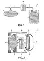
- Figure 1 shows an embodiment of a flexible container system 1 for separating bodily fluids, for instance blood and in particular blood platelet concentrate, by means of centrifugation.
- the container system 1 comprises a first container 2 and a second container 4.
- the content of containers 2,4 is in mutual connection using a hose or tube-like connecting conduit 3.
- a widened portion 30 is incorporated according to the invention in connecting conduit 3 between first 2 and second container 4. If desired, a plurality of connecting conduits can also be applied.
- Containers 2, 4, widened portion 30 in connecting conduit 3 as well as connecting conduit 3 itself are preferably formed from a flexible material, generally a transparent plastic.
- a blood platelet concentrate which is obtained in known manner by separating drawn blood into its constituents, is received in first container 2, after which container system 1 is placed in a centrifuge device, for instance of the Rotomat® type, and the blood platelet concentrate is separated into individual components under the influence of the occurring centrifugal force.
- a centrifuge device for instance of the Rotomat® type
- a mixture of multiple buffy coats for instance 4 to 6, can also be received in first container 2.
- the blood platelet concentrate is separated into a white-yellowish layer of platelets and white blood cells, and into a yellow top layer of plasma and platelets.
- the top layer of plasma and blood platelets is pressed via widened portion 30 to second container 4.
- This pressing can take place by exerting a pressure on first container 2 with pressing means 20 using pressurizing liquid or gas; and is preferably performed at a lower rotation speed of the centrifuge.
- the plasma with a relatively high platelet concentration is thus the first to be collected in second container 4.
- the device is further provided with clamping means 15 with which the connecting conduit 3 between containers 2, 4 can be blocked and/or unblocked as shown in figure 2 .
- the device comprises clamps 15 between first container 2 and widened portion 30, and between widened portion 30 and second container 4.
- the device further comprises detection means 25 for detecting the position of the separated fractions in widened portion 30, and more specifically of the separating layer between the leukocyte fraction and the plasma fraction, which can otherwise both comprise platelets.
- detection means 25 for detecting the position of the separated fractions in widened portion 30, and more specifically of the separating layer between the leukocyte fraction and the plasma fraction, which can otherwise both comprise platelets.
- Detection means comprise more precisely a light source disposed on one side (the front side or the rear side of the plane of figure 2 ) of widened portion 30, and a row of light-sensitive sensors which are disposed on the other side of widened portion 30 and which can measure the intensity of the light scattered by the fluid present in widened portion 30.
- the progress of the separating layer can be measured by disposing the row of sensors in the flow direction of the blood platelet concentrate, preferably along the whole length of the widened portion. This for instance allows precise adjustment of the rotation speed of the centrifuge subject to the measured position of the separating layer. It is thus possible for instance to decrease the rotation speed in stepwise manner the closer the separating layer moves to the outer end on the side of the second container.
- the specific densities of blood components differ very little.
- the red blood cells thus have a density of 1.10 g/ml, white blood cells a density of 1.07 g/ml, platelets a density of 1.05 g/ml and plasma a density of 1.03 g/ml.
- the clamp 15 is set into operation depending on the adjustment of the array of light-sensitive sensors 25, whereby the hose conduit 3 between widened portion 30 and collecting container 4 is closed and optionally sealed when the white-yellowish layer has neared the end of widened portion 30.
- collecting container 4 can be removed (after sealing of conduit 3) as well as first container 2 and widened portion 30.
- the first and second containers 2, 4 can take diverse forms in accordance with the type of device that is applied.
- containers with a form that is usual in the technical field, fillable via top and/or bottom, relatively flat and round, provided with a side opening, and so forth. It is also possible according to the invention to perform the method with a single buffy coat or unit of blood platelet-rich plasma.
- Figure 2 shows schematically a top view of a part of a device according to the present invention.
- the shown device is suitable for accommodating a container system 1 according to figure 1 and is intended for placing in a centrifuge device 21 as shown in figure 3 .
- the device part 8 shown in figure 2 comprises three mutually coupled receiving parts 10, 11 and 12, parts 10 and 12 of which are intended for accommodating a container 2, 4 and part 11 of which is intended for accommodating conduit 3 provided with widened portion 30. All components 2, 4, 30 can be coupled releasably to receiving parts 10, 11 and 12.
- receiving part 10 is adapted to accommodate first container 2 of container system 1.
- Receiving part 10 comprises a space substantially open on one side through which first container 2 can be placed in receiving part 10 and can be coupled thereto, optionally with the use of coupling means.
- Receiving part 11 is embodied in the shown exemplary embodiment such that conduits 3 and widened portion 30 can be accommodated therein.
- This receiving part 11 comprises a substantially flat element provided with recesses, among others in the form of widened portion 30, to enable optional easy placing and fixing thereof. If desired, the recess for widened portion 30 can be provided with a cover (not shown) in order to couple widened portion 30 releasably to receiving part 11.
- receiving part 12 is intended to accommodate second container 4.
- This receiving part 12 comprises a hollow space which can optionally be closed using hinged flaps (not shown).
- Second container 4 can herein be placed in the space, after which it is closed using the flaps.
- the device part 8 further comprises means 15, using which the connecting conduit 3 between containers 2 and 4 can be blocked and unblocked.
- These means 15 can comprise openings which co-act with blocking means coupled to the centrifuge device. Another option however is that these means 15 themselves comprise blocking means in the form of clamping means and/or welding devices.
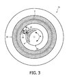
- FIG 3 shows another preferred embodiment of the device according to the present invention placed in a centrifuge device 21.
- the shown part of centrifuge device 21 comprises a recess or cavity 32 in which a relatively flat, annular container 2 can be accommodated.
- Figure 3 shows container 2 in top view.
- Centrifuge device 21 is further provided with a pressing member (not shown) which can expand when liquid or gas is supplied and can exert a pressure on first container 2 so that it is - largely - emptied due to the pressing.
- the pressing member can be situated in the cover or on the bottom of the recess of the centrifuge device and extends over practically the whole surface area of container 2.
- Centrifuge device 21 is further provided with a second recess 34 in which a second container 4 can be accommodated.
- Connecting conduit 3 is provided according to the invention with a widened portion 30.
- Light-sensitive sensors 25 can likewise be accommodated in device 21.
- Centrifuge device 21 is driven by a motor which enables the rotation in the directions R indicated in figure 3 .
- the operation of the device according to the present invention, in combination with container system 1, is as follows. As according to the above description, containers 2, 4 and connecting conduit 3 with widened portion 30 are accommodated in the device and coupled releasably thereto. Only container 2 is here filled with blood platelet concentrate. After placing in centrifuge device 21, the centrifuge device is set into operation. In this situation blocking means 15 are activated such that a blocking of connecting conduit 3 takes place so that the concentrate cannot flow from first container 2 to second container 4.
- blocking means 15 comprise clamping means and/or welding means which can be in the device itself as well as coupled to the centrifuge device. In the shown embodiment clamping means 15 are present on the device itself. The device moreover co-acts with detection and actuating means which are usually coupled to the centrifuge device and can actuate blocking means 15. In the starting situation the detection and actuating means are adjusted such that connecting conduit 3 is blocked. After a determined centrifugation period in which separation of the blood platelet concentrate into the separate components has taken place, blocking means 15 are actuated so that they unblock connecting conduit 3 and a flow of fluid can take place from first container 2 to widened portion 30 and second container 4.
- a blood platelet concentrate will be situated in second container 4 with a lower leukocyte content than has been usual heretofore. It is thus possible to obtain a blood platelet concentrate with a leukocyte content which is lower than 5 million per unit, preferably lower than 3 million per unit, most preferably lower than 1 million per unit.
- a unit is the usual term used by the skilled person for a therapeutic unit. This has great advantages because it is now no longer necessary to filter the blood platelet concentrate obtained by means of centrifugation in order to thus bring the leukocyte content to the desired low level. Filtering is undesirable because of the negative effects on at least a part of the constituents of the blood platelet concentrate.
Landscapes
- Health & Medical Sciences (AREA)
- Heart & Thoracic Surgery (AREA)
- Vascular Medicine (AREA)
- General Health & Medical Sciences (AREA)
- Veterinary Medicine (AREA)
- Engineering & Computer Science (AREA)
- Public Health (AREA)
- Hematology (AREA)
- Life Sciences & Earth Sciences (AREA)
- Animal Behavior & Ethology (AREA)
- Biomedical Technology (AREA)
- Anesthesiology (AREA)
- Cardiology (AREA)
- Pathology (AREA)
- Chemical Kinetics & Catalysis (AREA)
- Diabetes (AREA)
- Chemical & Material Sciences (AREA)
- Bioinformatics & Cheminformatics (AREA)
- General Chemical & Material Sciences (AREA)
- Medicinal Chemistry (AREA)
- Nuclear Medicine, Radiotherapy & Molecular Imaging (AREA)
- Organic Chemistry (AREA)
- Pharmacology & Pharmacy (AREA)
- External Artificial Organs (AREA)
- Medicines Containing Material From Animals Or Micro-Organisms (AREA)
- Centrifugal Separators (AREA)
Claims (14)
- Dispositif pour séparer un fluide corporel en fractions sous la force centrifuge, lequel dispositif comporte une centrifuge et un système de récipients flexible (1), le système de récipients (1) comportant au moins un premier récipient (2) pour le fluide pour être séparé et un second récipient (4) pour une fraction séparée, où les récipients (2, 4) sont mutuellement connectés en utilisant un conduit de connexion (3) pour un fluide, où une partie élargie (30) est disposée dans le conduit de connexion (3) entre le premier (2) et le second (4) récipient, et où pendant la centrifugation une couche de séparation détectable est créée dans la portion élargie, caractérisé en ce que le dispositif comprend de plus une rangée de moyens de détection (25) disposés sur la direction d'écoulement du fluide corporel le long de la direction de longueur totale ou partielle de la partie élargie pour détecter la position et le progrès des fractions séparées dans la partie élargie (30), et en particulier de la couche de séparation, le dispositif comprenant de plus le moyen permettant l'ajustement exacte de la vitesse de rotation de la centrifuge en fonction de la position mesurée de la couche de séparation.
- Dispositif selon la revendication 1, caractérisé en ce que le moyen de détection (25) comprend une source de lumière disposée sur un côté de la partie élargie (30) et une rangée de capteurs sensibles à lumière qui sont disposés sur l'autre côté de la partie élargie (30) et qui peuvent mesurer l'intensité de la lumière dispersée par le fluide présent dans la partie élargie (30).
- Dispositif selon la revendication 2, caractérisé en ce que la rangée de capteurs sensibles à lumière est disposée dans la direction d'écoulement du fluide corporel.
- Dispositif selon l'une quelconque des revendications antérieures, caractérisé en ce que le dispositif est pourvu avec le moyen (15) par l'utilisation duquel le conduit de connexion (3) entre le premier récipient (2) et la partie élargie (30) et/ou entre la partie élargie (30) et le second récipient (4) peut être bloqué et débloqué.
- Dispositif selon la revendication 4, caractérisé en ce que le moyen (15) avec lequel le conduit de connexion (3) entre les récipients (2, 4) peut être bloqué et débloqué comprend le moyen de blocage et/ou le moyen de soudage.
- Dispositif selon l'une quelconque des revendications antérieures, caractérisé en ce que le dispositif comprend le moyen d'actionnement, de sorte qu'un ou plusieurs moyens de blocage soient actionnés par le moyen d'actionnement qui répond à un signal généré par le moyen de détection.
- Dispositif selon l'une quelconque des revendications antérieures, caractérisé en ce que le dispositif comprend un système de récipients (1) comportant une pluralité de récipients, et où au moins une partie élargie (30) est disposée dans le conduit de connexion (3) entre au moins deux d'entre les récipients.
- Dispositif selon l'une quelconque des revendications antérieures, caractérisé en ce que le dispositif comprend le moyen de pression (20) ou le moyen de pompage, par l'utilisation duquel au moins le premier récipient (2) peut être soumis à une pression exercée de l'extérieur dudit récipient (2).
- Dispositif selon l'une quelconque des revendications antérieures, caractérisé en ce que le dispositif comprend une ou plusieurs parties de réception (10, 11, 12) pour accommoder un récipient (2, 4) et/ou une partie élargie (30), lesquelles parties sont adaptées de sorte qu'un récipient (2, 4) et/ou une partie élargie (30) puissent être y couplés de manière détachable.
- Procédé pour séparer le concentrât plaquettaire de sang en fractions sous la force centrifuge, comprenant les étapes de:a) pourvoir un dispositif centrifuge selon l'une quelconque des revendications 1-9;b) remplir le premier récipient (2) du système de récipients (1) avec le fluide à séparer;c) disposer le système de récipients (1) dans un dispositif centrifuge (21), de sorte que le premier récipient (2) soit soumis pendant l'opération à la plus grande force centrifuge;d) faire le dispositif centrifuge (21) tourner jusqu'à ce que la séparation désirée soit obtenue;e) éloigner le premier (2) et le second récipient (4) du dispositif centrifuge (21);
caractérisé en ce que pendant la centrifugation le fluide est pressé par la partie élargie au second récipient et une couche de séparation détectable est créée dans la partie élargie (30), la position des fractions séparées dans la partie élargie (30) est détectée au moins pendant l'étape d) par la rangée de moyens de détection (25) positionnés le long de la direction de longueur totale ou partielle de la partie élargie (30), et la vitesse de rotation du dispositif centrifuge (21) est ajustée en fonction de la position mesurée de la couche de séparation dans la partie élargie (30). - Procédé selon la revendication 10, caractérisé en ce que le fluide à séparer comprend un mélange de couches leucocytaires multiples.
- Procédé selon la revendication 10 ou 11, caractérisé en ce qu'au moins le premier récipient (2) du système de récipients (1) est soumis à une pression exercée de l'extérieur dudit récipient (2).
- Procédé selon l'une quelconque des revendications 10-12, caractérisé en ce que le conduit de connexion (3) entre le premier récipient (2) et la portion élargie (30) et/ou entre la portion élargie (30) et le second récipient (4) est bloqué quand une fraction indésirable pour le second récipient (4) est détecté à la position d'extrémité de la partie élargie.
- Procédé selon la revendication 13, caractérisé en ce que le conduit de connexion (3) entre le premier récipient (2) et la partie élargie (30) et/ou entre la partie élargie (30) et le second récipient (4) est bloqué après l'étape d).
Applications Claiming Priority (2)
| Application Number | Priority Date | Filing Date | Title |
|---|---|---|---|
| NL2000116A NL2000116C2 (nl) | 2006-06-29 | 2006-06-29 | Inrichting omvattende een houdersysteem voor een lichaamsvloeistof. |
| PCT/NL2007/050311 WO2008002135A1 (fr) | 2006-06-29 | 2007-06-27 | Dispositif comportant un système de récipients pour un fluide corporel |
Publications (2)
| Publication Number | Publication Date |
|---|---|
| EP2040850A1 EP2040850A1 (fr) | 2009-04-01 |
| EP2040850B1 true EP2040850B1 (fr) | 2015-02-18 |
Family
ID=37762433
Family Applications (1)
| Application Number | Title | Priority Date | Filing Date |
|---|---|---|---|
| EP07768912.3A Active EP2040850B1 (fr) | 2006-06-29 | 2007-06-27 | Dispositif comportant un système de récipients pour un fluide corporel |
Country Status (5)
| Country | Link |
|---|---|
| US (1) | US8333725B2 (fr) |
| EP (1) | EP2040850B1 (fr) |
| JP (1) | JP5211045B2 (fr) |
| NL (1) | NL2000116C2 (fr) |
| WO (1) | WO2008002135A1 (fr) |
Families Citing this family (12)
| Publication number | Priority date | Publication date | Assignee | Title |
|---|---|---|---|---|
| US7806779B2 (en) | 2008-05-19 | 2010-10-05 | Nike, Inc. | Putter heads and putters including polymeric material as part of the ball striking face |
| RU2500103C2 (ru) | 2008-11-28 | 2013-12-10 | Терумо Кабусики Кайся | Контейнерная система для крови и кассета |
| ITMI20090579A1 (it) * | 2009-04-09 | 2010-10-10 | Eurosets Srl | Dispositivo di controllo della ammissione di globuli rossi ad un paziente in linea di trasfusione. |
| EP2500048B1 (fr) | 2009-11-10 | 2023-09-27 | Terumo Kabushiki Kaisha | Unité d'insertion et système de poches de sang |
| US9022344B2 (en) | 2011-02-28 | 2015-05-05 | Fenwal, Inc. | Clamping systems and apparatus |
| WO2013109327A1 (fr) | 2012-01-16 | 2013-07-25 | Fenwal, Inc. | Systèmes de sac de sang pour la séparation du sang total et leurs procédés d'utilisation |
| US9327296B2 (en) | 2012-01-27 | 2016-05-03 | Fenwal, Inc. | Fluid separation chambers for fluid processing systems |
| US8803090B2 (en) | 2012-11-09 | 2014-08-12 | Fenwal, Inc. | Citrate detector for blood processing system |
| EP2982393B1 (fr) * | 2013-04-05 | 2023-02-15 | Terumo Kabushiki Kaisha | Système de prise en charge de poches de sang |
| JP6672262B2 (ja) * | 2015-03-18 | 2020-03-25 | テルモ株式会社 | 遠心分離機及びセグメント保持部 |
| US10207044B2 (en) | 2015-07-29 | 2019-02-19 | Fenwal, Inc. | Five-port blood separation chamber and methods of using the same |
| US12343738B2 (en) | 2021-04-05 | 2025-07-01 | Fenwal, Inc. | Continuous flow centrifugation chambers |
Family Cites Families (11)
| Publication number | Priority date | Publication date | Assignee | Title |
|---|---|---|---|---|
| NL8502465A (nl) * | 1985-09-10 | 1987-04-01 | Ver Nl Kanker Inst | Werkwijze en apparatuur voor het scheiden en isoleren van bloedkomponenten. |
| US4850952A (en) * | 1985-09-10 | 1989-07-25 | Figdor Carl G | Method and device for the separation and isolation of blood or bone marrow components |
| US4767397A (en) * | 1987-03-09 | 1988-08-30 | Damon Corporation | Apparatus for liquid separation |
| JPH0780058A (ja) * | 1993-09-20 | 1995-03-28 | Terumo Corp | バッグ連結体および成分の分離、移送方法 |
| DE4340678C2 (de) * | 1993-11-30 | 2000-07-06 | Hettich Andreas Gmbh & Co Kg | Zentrifuge zur Trennung von Blutbestandteilen und ähnlichen Flüssigkeiten |
| JP3282952B2 (ja) | 1995-10-16 | 2002-05-20 | テルモ株式会社 | バッグ加圧装置 |
| NL1006731C2 (nl) * | 1997-08-07 | 1999-02-09 | Stichting Cel Scheidings Techn | Inrichting voor houdersysteem. |
| JP4060504B2 (ja) * | 1999-12-17 | 2008-03-12 | テルモ株式会社 | 血液成分採取装置 |
| JP2001276663A (ja) | 2000-03-30 | 2001-10-09 | Haemonetics Corp | 粒子分離用遠心分離ボウル |
| WO2003086640A1 (fr) | 2002-04-12 | 2003-10-23 | Gambro, Inc. | Separation de fluides au moyen d'une centrifugeuse et d'une pompe a galets |
| US7087177B2 (en) * | 2004-04-16 | 2006-08-08 | Baxter International Inc. | Methods for determining flow rates of biological fluids |
-
2006
- 2006-06-29 NL NL2000116A patent/NL2000116C2/nl active Search and Examination
-
2007
- 2007-06-27 JP JP2009518017A patent/JP5211045B2/ja active Active
- 2007-06-27 EP EP07768912.3A patent/EP2040850B1/fr active Active
- 2007-06-27 US US12/306,321 patent/US8333725B2/en active Active
- 2007-06-27 WO PCT/NL2007/050311 patent/WO2008002135A1/fr not_active Ceased
Also Published As
| Publication number | Publication date |
|---|---|
| JP2009542308A (ja) | 2009-12-03 |
| EP2040850A1 (fr) | 2009-04-01 |
| US20090286221A1 (en) | 2009-11-19 |
| US8333725B2 (en) | 2012-12-18 |
| NL2000116C2 (nl) | 2008-01-02 |
| WO2008002135A1 (fr) | 2008-01-03 |
| WO2008002135B1 (fr) | 2008-02-14 |
| JP5211045B2 (ja) | 2013-06-12 |
Similar Documents
| Publication | Publication Date | Title |
|---|---|---|
| EP2040850B1 (fr) | Dispositif comportant un système de récipients pour un fluide corporel | |
| EP1494735B1 (fr) | Systeme et procede de traitement des composants sanguins | |
| US6629919B2 (en) | Core for blood processing apparatus | |
| US4416654A (en) | Pheresis apparatus | |
| JP3577444B2 (ja) | 血液処理遠心分離ボウルおよび全血から血漿分画を収集する方法 | |
| US4421503A (en) | Fluid processing centrifuge and apparatus thereof | |
| US4482342A (en) | Blood processing system for cell washing | |
| JP5161301B2 (ja) | 混合液を少なくとも2つの成分に分けるための装置および方法 | |
| EP2717942B1 (fr) | Système de séparation de sang comportant une soupape de gravité pour commander une chambre de séparation à robinet latéral | |
| KR101188482B1 (ko) | 소정 부피의 복합 액체를 적어도 두 성분으로 분리하기위한 장치 및 방법 | |
| EP2590697B1 (fr) | Système de séparation du sang comprenant une chambre de séparation à robinet latéral | |
| EP0070159A2 (fr) | Appareil centrifuge et méthodes pour la séparation de fluides en leurs composants | |
| HK1058498B (en) | Rotor core for blood processing apparatus |
Legal Events
| Date | Code | Title | Description |
|---|---|---|---|
| PUAI | Public reference made under article 153(3) epc to a published international application that has entered the european phase |
Free format text: ORIGINAL CODE: 0009012 |
|
| 17P | Request for examination filed |
Effective date: 20090129 |
|
| AK | Designated contracting states |
Kind code of ref document: A1 Designated state(s): AT BE BG CH CY CZ DE DK EE ES FI FR GB GR HU IE IS IT LI LT LU LV MC MT NL PL PT RO SE SI SK TR |
|
| AX | Request for extension of the european patent |
Extension state: AL BA HR MK RS |
|
| 17Q | First examination report despatched |
Effective date: 20111006 |
|
| DAX | Request for extension of the european patent (deleted) | ||
| RAP1 | Party data changed (applicant data changed or rights of an application transferred) |
Owner name: ANDREAS HETTICH GMBH & CO. KG |
|
| GRAP | Despatch of communication of intention to grant a patent |
Free format text: ORIGINAL CODE: EPIDOSNIGR1 |
|
| RIC1 | Information provided on ipc code assigned before grant |
Ipc: B04B 9/10 20060101ALI20140724BHEP Ipc: A61M 1/02 20060101ALI20140724BHEP Ipc: A61M 1/36 20060101ALI20140724BHEP Ipc: B04B 5/04 20060101AFI20140724BHEP Ipc: B04B 13/00 20060101ALI20140724BHEP |
|
| INTG | Intention to grant announced |
Effective date: 20140827 |
|
| GRAS | Grant fee paid |
Free format text: ORIGINAL CODE: EPIDOSNIGR3 |
|
| GRAA | (expected) grant |
Free format text: ORIGINAL CODE: 0009210 |
|
| AK | Designated contracting states |
Kind code of ref document: B1 Designated state(s): AT BE BG CH CY CZ DE DK EE ES FI FR GB GR HU IE IS IT LI LT LU LV MC MT NL PL PT RO SE SI SK TR |
|
| REG | Reference to a national code |
Ref country code: GB Ref legal event code: FG4D |
|
| REG | Reference to a national code |
Ref country code: CH Ref legal event code: EP |
|
| REG | Reference to a national code |
Ref country code: AT Ref legal event code: REF Ref document number: 710420 Country of ref document: AT Kind code of ref document: T Effective date: 20150315 |
|
| REG | Reference to a national code |
Ref country code: IE Ref legal event code: FG4D |
|
| REG | Reference to a national code |
Ref country code: DE Ref legal event code: R082 Ref document number: 602007040273 Country of ref document: DE Representative=s name: PUSCHMANN BORCHERT BARDEHLE PATENTANWAELTE PAR, DE |
|
| REG | Reference to a national code |
Ref country code: DE Ref legal event code: R096 Ref document number: 602007040273 Country of ref document: DE Effective date: 20150402 |
|
| REG | Reference to a national code |
Ref country code: FR Ref legal event code: PLFP Year of fee payment: 9 |
|
| REG | Reference to a national code |
Ref country code: NL Ref legal event code: VDEP Effective date: 20150218 |
|
| REG | Reference to a national code |
Ref country code: AT Ref legal event code: MK05 Ref document number: 710420 Country of ref document: AT Kind code of ref document: T Effective date: 20150218 |
|
| REG | Reference to a national code |
Ref country code: LT Ref legal event code: MG4D |
|
| PG25 | Lapsed in a contracting state [announced via postgrant information from national office to epo] |
Ref country code: SE Free format text: LAPSE BECAUSE OF FAILURE TO SUBMIT A TRANSLATION OF THE DESCRIPTION OR TO PAY THE FEE WITHIN THE PRESCRIBED TIME-LIMIT Effective date: 20150218 Ref country code: ES Free format text: LAPSE BECAUSE OF FAILURE TO SUBMIT A TRANSLATION OF THE DESCRIPTION OR TO PAY THE FEE WITHIN THE PRESCRIBED TIME-LIMIT Effective date: 20150218 Ref country code: LT Free format text: LAPSE BECAUSE OF FAILURE TO SUBMIT A TRANSLATION OF THE DESCRIPTION OR TO PAY THE FEE WITHIN THE PRESCRIBED TIME-LIMIT Effective date: 20150218 Ref country code: FI Free format text: LAPSE BECAUSE OF FAILURE TO SUBMIT A TRANSLATION OF THE DESCRIPTION OR TO PAY THE FEE WITHIN THE PRESCRIBED TIME-LIMIT Effective date: 20150218 |
|
| PG25 | Lapsed in a contracting state [announced via postgrant information from national office to epo] |
Ref country code: NL Free format text: LAPSE BECAUSE OF FAILURE TO SUBMIT A TRANSLATION OF THE DESCRIPTION OR TO PAY THE FEE WITHIN THE PRESCRIBED TIME-LIMIT Effective date: 20150218 Ref country code: GR Free format text: LAPSE BECAUSE OF FAILURE TO SUBMIT A TRANSLATION OF THE DESCRIPTION OR TO PAY THE FEE WITHIN THE PRESCRIBED TIME-LIMIT Effective date: 20150519 Ref country code: IS Free format text: LAPSE BECAUSE OF FAILURE TO SUBMIT A TRANSLATION OF THE DESCRIPTION OR TO PAY THE FEE WITHIN THE PRESCRIBED TIME-LIMIT Effective date: 20150618 Ref country code: AT Free format text: LAPSE BECAUSE OF FAILURE TO SUBMIT A TRANSLATION OF THE DESCRIPTION OR TO PAY THE FEE WITHIN THE PRESCRIBED TIME-LIMIT Effective date: 20150218 Ref country code: LV Free format text: LAPSE BECAUSE OF FAILURE TO SUBMIT A TRANSLATION OF THE DESCRIPTION OR TO PAY THE FEE WITHIN THE PRESCRIBED TIME-LIMIT Effective date: 20150218 |
|
| PG25 | Lapsed in a contracting state [announced via postgrant information from national office to epo] |
Ref country code: DK Free format text: LAPSE BECAUSE OF FAILURE TO SUBMIT A TRANSLATION OF THE DESCRIPTION OR TO PAY THE FEE WITHIN THE PRESCRIBED TIME-LIMIT Effective date: 20150218 Ref country code: CZ Free format text: LAPSE BECAUSE OF FAILURE TO SUBMIT A TRANSLATION OF THE DESCRIPTION OR TO PAY THE FEE WITHIN THE PRESCRIBED TIME-LIMIT Effective date: 20150218 Ref country code: RO Free format text: LAPSE BECAUSE OF FAILURE TO SUBMIT A TRANSLATION OF THE DESCRIPTION OR TO PAY THE FEE WITHIN THE PRESCRIBED TIME-LIMIT Effective date: 20150218 Ref country code: SK Free format text: LAPSE BECAUSE OF FAILURE TO SUBMIT A TRANSLATION OF THE DESCRIPTION OR TO PAY THE FEE WITHIN THE PRESCRIBED TIME-LIMIT Effective date: 20150218 Ref country code: EE Free format text: LAPSE BECAUSE OF FAILURE TO SUBMIT A TRANSLATION OF THE DESCRIPTION OR TO PAY THE FEE WITHIN THE PRESCRIBED TIME-LIMIT Effective date: 20150218 |
|
| REG | Reference to a national code |
Ref country code: DE Ref legal event code: R097 Ref document number: 602007040273 Country of ref document: DE |
|
| PG25 | Lapsed in a contracting state [announced via postgrant information from national office to epo] |
Ref country code: PL Free format text: LAPSE BECAUSE OF FAILURE TO SUBMIT A TRANSLATION OF THE DESCRIPTION OR TO PAY THE FEE WITHIN THE PRESCRIBED TIME-LIMIT Effective date: 20150218 |
|
| PLBE | No opposition filed within time limit |
Free format text: ORIGINAL CODE: 0009261 |
|
| STAA | Information on the status of an ep patent application or granted ep patent |
Free format text: STATUS: NO OPPOSITION FILED WITHIN TIME LIMIT |
|
| PG25 | Lapsed in a contracting state [announced via postgrant information from national office to epo] |
Ref country code: IT Free format text: LAPSE BECAUSE OF FAILURE TO SUBMIT A TRANSLATION OF THE DESCRIPTION OR TO PAY THE FEE WITHIN THE PRESCRIBED TIME-LIMIT Effective date: 20150218 |
|
| 26N | No opposition filed |
Effective date: 20151119 |
|
| PG25 | Lapsed in a contracting state [announced via postgrant information from national office to epo] |
Ref country code: MC Free format text: LAPSE BECAUSE OF FAILURE TO SUBMIT A TRANSLATION OF THE DESCRIPTION OR TO PAY THE FEE WITHIN THE PRESCRIBED TIME-LIMIT Effective date: 20150218 |
|
| REG | Reference to a national code |
Ref country code: CH Ref legal event code: PL |
|
| PG25 | Lapsed in a contracting state [announced via postgrant information from national office to epo] |
Ref country code: SI Free format text: LAPSE BECAUSE OF FAILURE TO SUBMIT A TRANSLATION OF THE DESCRIPTION OR TO PAY THE FEE WITHIN THE PRESCRIBED TIME-LIMIT Effective date: 20150218 Ref country code: LU Free format text: LAPSE BECAUSE OF FAILURE TO SUBMIT A TRANSLATION OF THE DESCRIPTION OR TO PAY THE FEE WITHIN THE PRESCRIBED TIME-LIMIT Effective date: 20150627 |
|
| REG | Reference to a national code |
Ref country code: IE Ref legal event code: MM4A |
|
| PG25 | Lapsed in a contracting state [announced via postgrant information from national office to epo] |
Ref country code: IE Free format text: LAPSE BECAUSE OF NON-PAYMENT OF DUE FEES Effective date: 20150627 Ref country code: LI Free format text: LAPSE BECAUSE OF NON-PAYMENT OF DUE FEES Effective date: 20150630 Ref country code: CH Free format text: LAPSE BECAUSE OF NON-PAYMENT OF DUE FEES Effective date: 20150630 |
|
| REG | Reference to a national code |
Ref country code: FR Ref legal event code: PLFP Year of fee payment: 10 |
|
| PG25 | Lapsed in a contracting state [announced via postgrant information from national office to epo] |
Ref country code: MT Free format text: LAPSE BECAUSE OF FAILURE TO SUBMIT A TRANSLATION OF THE DESCRIPTION OR TO PAY THE FEE WITHIN THE PRESCRIBED TIME-LIMIT Effective date: 20150218 |
|
| PG25 | Lapsed in a contracting state [announced via postgrant information from national office to epo] |
Ref country code: BG Free format text: LAPSE BECAUSE OF FAILURE TO SUBMIT A TRANSLATION OF THE DESCRIPTION OR TO PAY THE FEE WITHIN THE PRESCRIBED TIME-LIMIT Effective date: 20150218 Ref country code: HU Free format text: LAPSE BECAUSE OF FAILURE TO SUBMIT A TRANSLATION OF THE DESCRIPTION OR TO PAY THE FEE WITHIN THE PRESCRIBED TIME-LIMIT; INVALID AB INITIO Effective date: 20070627 |
|
| REG | Reference to a national code |
Ref country code: FR Ref legal event code: PLFP Year of fee payment: 11 |
|
| PG25 | Lapsed in a contracting state [announced via postgrant information from national office to epo] |
Ref country code: CY Free format text: LAPSE BECAUSE OF FAILURE TO SUBMIT A TRANSLATION OF THE DESCRIPTION OR TO PAY THE FEE WITHIN THE PRESCRIBED TIME-LIMIT Effective date: 20150218 |
|
| PG25 | Lapsed in a contracting state [announced via postgrant information from national office to epo] |
Ref country code: TR Free format text: LAPSE BECAUSE OF FAILURE TO SUBMIT A TRANSLATION OF THE DESCRIPTION OR TO PAY THE FEE WITHIN THE PRESCRIBED TIME-LIMIT Effective date: 20150218 |
|
| PG25 | Lapsed in a contracting state [announced via postgrant information from national office to epo] |
Ref country code: PT Free format text: LAPSE BECAUSE OF FAILURE TO SUBMIT A TRANSLATION OF THE DESCRIPTION OR TO PAY THE FEE WITHIN THE PRESCRIBED TIME-LIMIT Effective date: 20150218 |
|
| REG | Reference to a national code |
Ref country code: FR Ref legal event code: PLFP Year of fee payment: 12 |
|
| P01 | Opt-out of the competence of the unified patent court (upc) registered |
Effective date: 20230530 |
|
| PGFP | Annual fee paid to national office [announced via postgrant information from national office to epo] |
Ref country code: DE Payment date: 20250610 Year of fee payment: 19 |
|
| PGFP | Annual fee paid to national office [announced via postgrant information from national office to epo] |
Ref country code: GB Payment date: 20250620 Year of fee payment: 19 |
|
| PGFP | Annual fee paid to national office [announced via postgrant information from national office to epo] |
Ref country code: BE Payment date: 20250617 Year of fee payment: 19 |
|
| PGFP | Annual fee paid to national office [announced via postgrant information from national office to epo] |
Ref country code: FR Payment date: 20250624 Year of fee payment: 19 |