EP2041455B1 - Hydraulisches energierückgewinnungssystem - Google Patents
Hydraulisches energierückgewinnungssystem Download PDFInfo
- Publication number
- EP2041455B1 EP2041455B1 EP07823530A EP07823530A EP2041455B1 EP 2041455 B1 EP2041455 B1 EP 2041455B1 EP 07823530 A EP07823530 A EP 07823530A EP 07823530 A EP07823530 A EP 07823530A EP 2041455 B1 EP2041455 B1 EP 2041455B1
- Authority
- EP
- European Patent Office
- Prior art keywords
- pressure
- low
- circuit
- energy recovery
- fluid source
- Prior art date
- Legal status (The legal status is an assumption and is not a legal conclusion. Google has not performed a legal analysis and makes no representation as to the accuracy of the status listed.)
- Ceased
Links
Images





Classifications
-
- F—MECHANICAL ENGINEERING; LIGHTING; HEATING; WEAPONS; BLASTING
- F16—ENGINEERING ELEMENTS AND UNITS; GENERAL MEASURES FOR PRODUCING AND MAINTAINING EFFECTIVE FUNCTIONING OF MACHINES OR INSTALLATIONS; THERMAL INSULATION IN GENERAL
- F16H—GEARING
- F16H61/00—Control functions within control units of change-speed- or reversing-gearings for conveying rotary motion ; Control of exclusively fluid gearing, friction gearing, gearings with endless flexible members or other particular types of gearing
- F16H61/38—Control of exclusively fluid gearing
- F16H61/40—Control of exclusively fluid gearing hydrostatic
- F16H61/4157—Control of braking, e.g. preventing pump over-speeding when motor acts as a pump
-
- B—PERFORMING OPERATIONS; TRANSPORTING
- B60—VEHICLES IN GENERAL
- B60K—ARRANGEMENT OR MOUNTING OF PROPULSION UNITS OR OF TRANSMISSIONS IN VEHICLES; ARRANGEMENT OR MOUNTING OF PLURAL DIVERSE PRIME-MOVERS IN VEHICLES; AUXILIARY DRIVES FOR VEHICLES; INSTRUMENTATION OR DASHBOARDS FOR VEHICLES; ARRANGEMENTS IN CONNECTION WITH COOLING, AIR INTAKE, GAS EXHAUST OR FUEL SUPPLY OF PROPULSION UNITS IN VEHICLES
- B60K6/00—Arrangement or mounting of plural diverse prime-movers for mutual or common propulsion, e.g. hybrid propulsion systems comprising electric motors and internal combustion engines
- B60K6/08—Prime-movers comprising combustion engines and mechanical or fluid energy storing means
- B60K6/12—Prime-movers comprising combustion engines and mechanical or fluid energy storing means by means of a chargeable fluidic accumulator
-
- F—MECHANICAL ENGINEERING; LIGHTING; HEATING; WEAPONS; BLASTING
- F16—ENGINEERING ELEMENTS AND UNITS; GENERAL MEASURES FOR PRODUCING AND MAINTAINING EFFECTIVE FUNCTIONING OF MACHINES OR INSTALLATIONS; THERMAL INSULATION IN GENERAL
- F16H—GEARING
- F16H61/00—Control functions within control units of change-speed- or reversing-gearings for conveying rotary motion ; Control of exclusively fluid gearing, friction gearing, gearings with endless flexible members or other particular types of gearing
- F16H61/38—Control of exclusively fluid gearing
- F16H61/40—Control of exclusively fluid gearing hydrostatic
- F16H61/4008—Control of circuit pressure
- F16H61/4026—Control of low pressure
-
- F—MECHANICAL ENGINEERING; LIGHTING; HEATING; WEAPONS; BLASTING
- F16—ENGINEERING ELEMENTS AND UNITS; GENERAL MEASURES FOR PRODUCING AND MAINTAINING EFFECTIVE FUNCTIONING OF MACHINES OR INSTALLATIONS; THERMAL INSULATION IN GENERAL
- F16H—GEARING
- F16H61/00—Control functions within control units of change-speed- or reversing-gearings for conveying rotary motion ; Control of exclusively fluid gearing, friction gearing, gearings with endless flexible members or other particular types of gearing
- F16H61/38—Control of exclusively fluid gearing
- F16H61/40—Control of exclusively fluid gearing hydrostatic
- F16H61/4043—Control of a bypass valve
-
- F—MECHANICAL ENGINEERING; LIGHTING; HEATING; WEAPONS; BLASTING
- F16—ENGINEERING ELEMENTS AND UNITS; GENERAL MEASURES FOR PRODUCING AND MAINTAINING EFFECTIVE FUNCTIONING OF MACHINES OR INSTALLATIONS; THERMAL INSULATION IN GENERAL
- F16H—GEARING
- F16H61/00—Control functions within control units of change-speed- or reversing-gearings for conveying rotary motion ; Control of exclusively fluid gearing, friction gearing, gearings with endless flexible members or other particular types of gearing
- F16H61/38—Control of exclusively fluid gearing
- F16H61/40—Control of exclusively fluid gearing hydrostatic
- F16H61/4061—Control related to directional control valves, e.g. change-over valves, for crossing the feeding conduits
-
- F—MECHANICAL ENGINEERING; LIGHTING; HEATING; WEAPONS; BLASTING
- F16—ENGINEERING ELEMENTS AND UNITS; GENERAL MEASURES FOR PRODUCING AND MAINTAINING EFFECTIVE FUNCTIONING OF MACHINES OR INSTALLATIONS; THERMAL INSULATION IN GENERAL
- F16H—GEARING
- F16H61/00—Control functions within control units of change-speed- or reversing-gearings for conveying rotary motion ; Control of exclusively fluid gearing, friction gearing, gearings with endless flexible members or other particular types of gearing
- F16H61/38—Control of exclusively fluid gearing
- F16H61/40—Control of exclusively fluid gearing hydrostatic
- F16H61/4078—Fluid exchange between hydrostatic circuits and external sources or consumers
- F16H61/4139—Replenishing or scavenging pumps, e.g. auxiliary charge pumps
-
- F—MECHANICAL ENGINEERING; LIGHTING; HEATING; WEAPONS; BLASTING
- F16—ENGINEERING ELEMENTS AND UNITS; GENERAL MEASURES FOR PRODUCING AND MAINTAINING EFFECTIVE FUNCTIONING OF MACHINES OR INSTALLATIONS; THERMAL INSULATION IN GENERAL
- F16H—GEARING
- F16H61/00—Control functions within control units of change-speed- or reversing-gearings for conveying rotary motion ; Control of exclusively fluid gearing, friction gearing, gearings with endless flexible members or other particular types of gearing
- F16H61/38—Control of exclusively fluid gearing
- F16H61/40—Control of exclusively fluid gearing hydrostatic
- F16H61/4148—Open loop circuits
-
- F—MECHANICAL ENGINEERING; LIGHTING; HEATING; WEAPONS; BLASTING
- F16—ENGINEERING ELEMENTS AND UNITS; GENERAL MEASURES FOR PRODUCING AND MAINTAINING EFFECTIVE FUNCTIONING OF MACHINES OR INSTALLATIONS; THERMAL INSULATION IN GENERAL
- F16H—GEARING
- F16H61/00—Control functions within control units of change-speed- or reversing-gearings for conveying rotary motion ; Control of exclusively fluid gearing, friction gearing, gearings with endless flexible members or other particular types of gearing
- F16H61/38—Control of exclusively fluid gearing
- F16H61/40—Control of exclusively fluid gearing hydrostatic
- F16H61/4078—Fluid exchange between hydrostatic circuits and external sources or consumers
- F16H61/4096—Fluid exchange between hydrostatic circuits and external sources or consumers with pressure accumulators
-
- F—MECHANICAL ENGINEERING; LIGHTING; HEATING; WEAPONS; BLASTING
- F16—ENGINEERING ELEMENTS AND UNITS; GENERAL MEASURES FOR PRODUCING AND MAINTAINING EFFECTIVE FUNCTIONING OF MACHINES OR INSTALLATIONS; THERMAL INSULATION IN GENERAL
- F16H—GEARING
- F16H61/00—Control functions within control units of change-speed- or reversing-gearings for conveying rotary motion ; Control of exclusively fluid gearing, friction gearing, gearings with endless flexible members or other particular types of gearing
- F16H61/38—Control of exclusively fluid gearing
- F16H61/40—Control of exclusively fluid gearing hydrostatic
- F16H61/42—Control of exclusively fluid gearing hydrostatic involving adjustment of a pump or motor with adjustable output or capacity
- F16H61/423—Motor capacity control by fluid pressure control means
-
- Y—GENERAL TAGGING OF NEW TECHNOLOGICAL DEVELOPMENTS; GENERAL TAGGING OF CROSS-SECTIONAL TECHNOLOGIES SPANNING OVER SEVERAL SECTIONS OF THE IPC; TECHNICAL SUBJECTS COVERED BY FORMER USPC CROSS-REFERENCE ART COLLECTIONS [XRACs] AND DIGESTS
- Y02—TECHNOLOGIES OR APPLICATIONS FOR MITIGATION OR ADAPTATION AGAINST CLIMATE CHANGE
- Y02T—CLIMATE CHANGE MITIGATION TECHNOLOGIES RELATED TO TRANSPORTATION
- Y02T10/00—Road transport of goods or passengers
- Y02T10/60—Other road transportation technologies with climate change mitigation effect
- Y02T10/62—Hybrid vehicles
Definitions
- the present invention relates to a hydraulic energy recovery circuit, comprising at least one hydraulic motor, two main ducts for supplying or exhausting the at least one motor, a source of low pressure fluid and a high pressure accumulator forming high pressure fluid source, the circuit being adapted to operate in a mode of energy recovery in which the main supply duct is connected to the source of low pressure fluid and the main exhaust duct is connected to the high pressure accumulator, and in a mode of energy return in which the main supply duct is connected to the high pressure accumulator and the main exhaust duct is connected to the source of low pressure fluid.
- WO 98/47732 discloses the features of the preamble of claim 1. In general the pressure reliefs are adjustable, see US 4204405 .
- hybrid vehicles comprising a conventional propulsion engine (for example of the thermal type) and a circuit of the aforementioned type, the hydraulic motor (s) of which can be mechanically linked to the propulsion device, for example by being related to the output of this device, or to a wheel of the vehicle.
- the vehicle In cruising mode, the vehicle is normally driven by its conventional propulsion engine.
- Energy recovery occurs in a braking phase, during which the hydraulic motor is driven by the propulsion of the vehicle during braking, to operate as a pump and supply the high pressure fluid accumulator.
- the energy return occurs in particular during a vehicle acceleration phase, during which the hydraulic motor is again activated and is powered by the high pressure fluid from the accumulator, to provide a driving torque of vehicle propulsion assistance.
- a low-pressure accumulator is conventionally used as a source of low-pressure fluid, the shape and dimensions of which may pose congestion problems.
- booster pump whose supply is connected to a tank at atmospheric pressure of a freer form and therefore easier to integrate into the vehicle.
- This booster pump is sized to provide optimum feeding of the cylinders or hydraulic motors during the energy recovery phase, while the flow is maximum.
- Such pumps are conventionally fixed-set, that is to say they are associated with a fixed-setting pressure limiter, limiting the pressure delivered to a single predetermined value.
- the hydrostatic braking torque produced by the hydraulic motor or motors in the energy recovery phase and the engine torque delivered by this or these engines in the energy recovery phase is equal to the product of the engine displacement and the difference between the high pressure of the high pressure accumulator and the low pressure of the pump.
- This high pressure is imposed by the accumulator, depending on its charge level, while, as previously indicated, the low pressure is imposed by the fixed setting of the pump. If, moreover, the displacement of the engine is fixed, it is not possible to adjust the hydrostatic braking torque or the engine torque to the real need.
- the present invention aims to remedy these disadvantages or, at least, to attenuate them significantly.
- the low-pressure fluid source comprises a high-flow booster pump capable of delivering, from a reservoir without overpressure, a flow of fluid sufficient to supply the fluid supply of the at least one a hydraulic motor while the latter is at maximum speed in the energy recovery mode, and an adjustable pressure limiter that can be controlled to vary the pressure of the fluid at the source of fluid at low pressure.
- the adjustable pressure limiter makes it possible, whatever the type of hydraulic motor used, to set the low pressure to a level necessary to adjust the engine torque and avoid cavitation, in the energy recovery phase and in the recovery phase. 'energy.
- the outlet pressure of the source of fluid at low pressure it is possible to choose to adjust the outlet pressure of the source of fluid at low pressure to a level necessary to supply the hydraulic motor or motors (whose speed is imposed by the propulsion conventional vehicle) without cavitation, allowing this or these engines to pump a maximum amount of fluid to optimize the charging of the high pressure accumulator.
- the energy recovery phase it is possible to set the low pressure to a minimum level to obtain a high assistance torque.
- the circuit comprises means for activating or deactivating the high-rate booster pump, preferably associated with a non-return valve preventing the return of the fluid to said pump.
- the circuit comprises means for detecting at least one parameter indicating the state of the circuit and for controlling the adjustable pressure limiter according to said at least one parameter.
- this revealing parameter includes the charge level of the high pressure accumulator.
- the high pressure of the circuit which is the pressure required to fill the high pressure accumulator
- the braking torque would therefore increase with the level of charge of the accumulator. This is not always desirable, in particular because this increase may occur at the end of a braking phase of the vehicle, while the speed of this vehicle has already significantly decreased, so that a couple of constant braking would be enough.
- the circuit comprises means for controlling the adjustable pressure limiter according to an operating setpoint of said at least one hydraulic motor.
- the operating setpoint refers to the output torque of the motor.
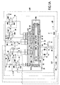
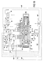
- the circuit represented on FIGS. 1A to 1E comprises a hydraulic motor 10 with two main ducts, respectively 12 and 14 for its fluid supply or exhaust. It also comprises a source of low-pressure fluid 16 formed by a high-rate booster pump, which pumps the fluid into a tank R without overpressure (at atmospheric pressure). This pump is chosen to be able to deliver a flow of fluid sufficient to ensure the fluid supply of the hydraulic motor while it is at maximum speed, in the energy recovery configuration. If several motors are present in the circuit, it is advantageous to use a same high-speed feeding pump, sized to deliver the flow of fluid sufficient to ensure the supply without cavitation of the various motors when they are in maximum speed in this configuration.
- the pump 16 is driven by a motor which can be the engine of the conventional propulsion of the vehicle. Means are provided to activate or deactivate the pump 16. In this case, it is equipped with an electromagnetic clutch 18.
- the circuit also comprises a source of high pressure fluid, formed by an accumulator 20.
- the engine 10 is of the clutchable and disengageable type. This is for example a hydraulic motor with radial pistons and fixed displacement.
- the inner space of the engine casing is pressurized while the main ducts of the engine are connected to an enclosure without overpressure (tank) or at a pressure substantially lower than the pressure of the crankcase of the engine.
- a pipe 22 connected to a pressure source opens into the interior space of the housing.
- the pressure source used is a pump 24 which, as will be seen hereinafter, is also the source of clutch fluid, to which the interior space of the engine casing is connected via a restriction 26 disposed on the pipe 22.
- the circuit comprises a hydraulic valve 30 which comprises a valve body 32 having an internal bore 34 within which a slide 36 is slidably mounted.
- the valve body 32 has a supply channel VA connected to the main supply duct 12, an exhaust duct VE connected to the main exhaust duct 14, a low-pressure connection duct VB connected to the fluid source to low pressure 16, a high-pressure connection way VH connected to the high pressure accumulator 20 and an auxiliary channel VX connected to an auxiliary line.
- the hydraulic valve 30 also has a first control chamber 38A connected to a first control channel VC1 and a second control chamber 38B, connected to a second control channel VC2.
- the slide 36 is shown in its neutral position, in which it is permanently recalled by a spring 40, so that the slide takes up its neutral position when the fluid pressure in the control chambers 38A and 38B is equal or substantially equal .
- this drawer in the neutral position of the drawer visible on the Figures 1A , 1B and 1D this drawer is centrally located in the valve body 32.
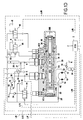
- the drawer In the energy recovery configuration of the figure 1C , the drawer has been moved to a first extreme position (in this case, to the right) by an increase in the pressure in the control chamber 38A whose volume has increased.
- these means comprise a first control solenoid valve 44, a first channel 44A is connected to the first control channel VC1, a second channel 44B is connected to the pump 24 , and a third channel 44C is connected to the tank R.
- a first control solenoid valve 44 In its rest position represented on the Figure 1A the channels 44A and 44C are connected, so that the first control chamber 38A is connected to the tank R, while the channel 44B is isolated.
- the solenoid valve 44 On receipt of a first control signal transmitted in a line L44 by an electronic control unit ECU, the solenoid valve 44 passes into its activated position, in which the channels 44B and 44A are connected while the channel 44C is isolated, of so that the control chamber 38A is supplied by the pressurized fluid from the pump 24. Thus, the spool goes into its first extreme position shown on the figure 1C .
- the solenoid valve means further comprise a second pilot solenoid valve 46 which has a first channel 46A connected to the second control channel VC2, a second channel 46B connected to the pump 24 and a third channel 46C connected to the tank R.
- the circuit further comprises a disengaging solenoid valve 48 which has a first channel 48A which is connected to the auxiliary channel VX of the valve 30, a second channel 48B which is connected to the pump 24 and a third channel 48C which is connected to the tank R
- a disengaged position of the valve 48 which in this case is its rest position
- the tracks 48A and 48C are connected in isolation from the channel 48B, so that the auxiliary channel VX of the valve 38 is connected. to the tank.
- the clutch position of the solenoid valve 48 which in this case is its activated position in which it is controlled by a command signal issued by the ECU in the control line L48, its channels 48A and 48B are connected, so that the auxiliary channel VX of the valve 30 is connected to the pump 24.
- a low capacitance accumulator 50 (thus compact) is disposed in shunt on the connection between the pump 24 and the channels 44B, 46B and 48B of these valves.
- the pump 24 serves both to control the displacement of the slide 36 and to that of the clutch / clutch of the motor 10.
- Any excess pressure in the accumulator 20 can be relieved in the tank R, to which this accumulator is connected by a pressure limiter 21.
- the high-speed pump 16 is equipped with an electromagnetic clutch 18 which makes it possible to activate this pump only when it is necessary, in particular during the energy recovery phase.
- the clutch 18 is controlled by a control signal transmitted by the ECU in the control line L18.
- the pump 16 does not operate unnecessarily, which saves energy.
- the circuit comprises an adjustable pressure limiter 52 for varying the pressure in the low-pressure connection path VB.
- this pressure limiter 52 is disposed on a connection between the discharge port of the pump 16 and the reservoir R.
- This pressure limiter In this case, the adjustable regulator 52 is of electrovalve type and is connected to the control unit ECU by a control line L52.
- the low-pressure connection path VB serves to supply the motor 10 and it is then desirable to adjust the pressure at the outlet of the pump 16 to a level necessary to supply the hydraulic motor (s). without cavitation.
- the link path VB which is connected to the engine exhaust, must discharge the fluid to the tank R and it is then preferable that the pressure limiter 52 be set to a minimum pressure level, or even zero pressure.
- the pump 16 is deactivated and a non-return valve 58 prevents the fluid discharged by the motor 10 from returning to the pump 16 so that the regulation of the low pressure is ensured by the limiter 58.
- the internal space of the crankcase of the engine 10 is connected to a secondary accumulator 54 of small capacity which makes it possible to keep sufficient fluid pressure on standby to rapidly disengage the engine 10 when this is necessary.
- This connection is made by a motor leakage return duct, on which duct a pressure limiter 56 is arranged, downstream of the connection point of the accumulator 54 to this duct 15.
- a pressure limiter 43 is connected to the outlet of the pump 24. It makes it possible to define the clutch and steering pressure.
- VA, VE exhaust and VX auxiliary supply channels then communicate with each other by means of grooves 37A, 37B and 37C and an axial bore 37D of the slide.
- a fourth throat 37E of the drawer is isolated from the previous ones, isolates the VB path from the other channels.
- the ECU electronic control unit is informed of the running conditions of the vehicle, in particular a deceleration or acceleration of the latter, and therefore a need for recovery or restitution of energy by information I.
- the ECU sends a clutch signal in the line L48 and thus controls the solenoid valve 48 in its activated position, thus allowing the fluid supply of the VX auxiliary channel.
- the main supply and exhaust ducts 12 and 14 of the engine are then put to the same pressure (so that the engine still produces no significant torque) but this pressure delivered by the pump 24 and possibly the accumulator 50, is sufficiently greater than the pressure in the crankcase of the engine to push the pistons of the engine against the cam of the latter. The engine is then engaged.
- the Figure 1B shows the situation when clutching the engine. It can be seen that the drawer has remained in its neutral position, without modifying the connection between the channels VA, VE and VX nor the isolation of the channel VB, but that the solenoid valve 48 is in its clutch position.
- the electronic control unit ECU emits a first control signal in the line L44 to turn the solenoid valve 44 into the activated position, so as to control the movement of the drawer in its first position. extreme power supply of the control chamber 38A.
- the adjustable pressure limiter 52 is then set to the desired pressure level.
- This setting will be detailed in the description of the Figure 4A .
- this level is that obtained by the emission of a signal of control of the pressure limiter 52 in the line L52, by the ECU unit.
- the motor 10 is rotated by its mechanical connection with the propulsion of the vehicle, and it operates as a pump by supplying the high pressure accumulator 20 with the fluid from the pump 16.
- a pressure sensor N detecting the pressure level in the accumulator 20, that is to say the charge level of the latter, and this information is transmitted to the ECU unit by a line LN .
- the ECU unit can be parameterized so that, in the energy recovery phase, there is a constant difference between the high pressure of the accumulator 20 and the low pressure delivered by the pump 16, so as to obtain a constant hydrostatic braking torque. or to ensure a variation of this difference, according to a determined variation law, as a function of the actual needs in hydrostatic braking torque, in particular by producing a lower hydrostatic braking torque towards the end of a deceleration phase.
- the energy recovery phase may continue for the duration of the deceleration or, if a maximum charge level of the accumulator 20 is detected by the sensor N, this phase may possibly terminate before the end of the deceleration.
- Other types of information may signal the end of the energy recovery phase, such as, for example, an opening of the pressure limiter 21.
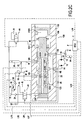
- the configuration of the figure 1D corresponds to a balancing phase, in which the main ducts 12 and 14 of the motor communicate with each other.
- the solenoid valve 48 can remain in its clutch position during a first period of this balancing phase, to keep the engine engaged, in order to allow a fast passage into the energy recovery phase if necessary or a resumption of the energy recovery phase if braking resumes.
- the clutch signal ceases, allowing the passage of the solenoid valve 48 in its configuration corresponding to the clutch, in which the auxiliary channel VX is connected to the reservoir R.
- the supply path VA and the high pressure path VH of the valve 30 are connected by the groove 37A, the bore 37D and the groove 37C of the slide 36, being isolated from the other channels.
- the exhaust path VE and the low pressure path VB are connected by the groove 37E of the slide being isolated from the other grooves, and the auxiliary path VX is isolated from the other grooves.
- the end of the energy recovery phase is noted by the ECU unit, for example when the information I transmitted to the latter reveals that the vehicle has reached a sufficient speed or that acceleration stops. It is also stopped when the accumulator 20 no longer has sufficient fluid pressure, particularly when the sensor N reveals a low pressure level in this accumulator.
- the pressure limiter 52 is set to minimum pressure, or even zero, This setting is for example obtained when the signal in the line L52 ceases. It should also be noted that the pressure limiter 52 is advantageously set to the minimum pressure level from the beginning of the balancing phase or, at least, from the end of the first period of this phase. To minimize the low pressure during the acceleration phase, the pump 16 can be deactivated by appropriate control or absence of a control signal in the line of command L18. The low pressure is then only regulated by the pressure limiter 52.
- the information I received by the ECU can relate to the traffic conditions of the vehicle equipped with the circuit, allowing the ECU to determine an operating setpoint of the hydraulic motor or motors and to control accordingly.
- the pressure limiter 52 to obtain the desired low pressure level.
- this setpoint can take into account the desired level of acceleration, revealed by the amplitude of support on the accelerator pedal or the amplitude of displacement of an acceleration lever ("joystick"), as well as than the speed of the vehicle.
- the operating instruction relates in particular to the output torque of the hydraulic motor or motors, which can be chosen to make progressive, by increasing it rapidly at the beginning of the energy recovery phase, while maintaining it at a level stabilized at the heart of this phase and decreasing it towards the end of this phase.
- the level of the effective low pressure can be detected by a sensor N 'and transmitted to the ECU unit by a line LN'.
- the same channel VX ' is both the auxiliary channel and the second control channel which supplies the control chamber 138B (it could be that which supplies the chamber 138A).
- a hole 133 of the body 132 of the valve 130 its path VA opens into its bore 134 in two distinct locations, respectively VA1 and VA2, spaced apart from each other in the direction of movement of the slide.
- the latter has three transverse holes 137A, 137B and 137C, interconnected by a blind bore 137D which opens in the chamber 138B. This hole opens in the chamber (in this case, 138B) to which is connected the auxiliary channel.
- the first channels 44A and 46A of the valves 44 and 46 are respectively connected to the control chambers 138A and 138B.
- the drawer is in its neutral position and it is seen that the channels VA and VE communicate with each other and with the channel VX ', by the holes 137A to 137D of the drawer.
- the solenoid valve 46 is then in its neutral position, in which it connects the channel VX 'to the tank R, the main ducts 12 and 14 of the engine 10 are then connected to the tank, so that the engine is disengaged.
- the selection signal for engaging the motor 10 consists of the first control signals, respectively transmitted in lines L44 and L46 by the ECU to control the two solenoid valves 44 and 46 in their activated positions.
- the two control chambers 138A and 138B are both connected to the outlet of the pump 24, so that the pressure in these two chambers is the same and the drawer remains in its neutral position, in which it is constantly recalled by the spring 40.
- the first control signal L44 is continued to be sent in the control line L44 to continue supplying fluid to the first control chamber 138A, but the signal is stopped. in the line L46 so that the valve 46 returns to its rest position, in which it connects the channel VX 'and therefore the second control chamber 138B to the tank R.
- the drawer is controlled in its first extreme position (in this case, to the left).
- the supply path VA is connected to the low pressure path VB, through the groove 137E of the slide 136 which is facing both the VA2 port VA and the VB channel.
- VA and VB channels are isolated from the other channels.
- the VE channel is connected to the VH channel by 137F throat of the drawer.
- the VX 'channel is isolated from the other channels. This is the situation that the Figure 2C .
- the ECU sends a control signal again in line L46, which which activates the solenoid valve 46 and thus also supplies the chamber 138B from the pump 24, thereby putting this chamber at the same pressure as the chamber 138A.
- the situation is then the same as that of the Figure 2B except that the fluid level in the accumulator 20 has increased.
- the ECU stops transmitting the control signals in lines L44 and L46, so that the valves 44 and 46 return to their neutral positions, thus returning to the configuration of the Figure 2A , wherein the supply and exhaust ducts 12 and 14 are connected to the tank.
- the energy restitution phase is carried out by putting the circuit in the configuration represented in FIG. 2D figure , obtained by placing only the valve 46 in its active position, so that only the control chamber 138B is supplied with fluid, by way VX ', and that the drawer is moved to its second extreme position (in this case, to the right).
- the track VA communicates with the track VH by the groove 137F of the drawer, which is opposite both the track VH and the first port VA1 of the track VA.
- the second port of this channel is closed by the drawer.
- the VE channel communicates with the VB channel 137E throat that is opposite these two channels, while the VX channel is isolated from other channels.
- the electronic control unit ECU is able to receive information from different sensors.
- the information I that enables it to trigger the recovery or energy recovery phases may be based on the measurements of different sensors, referring in particular to braking or acceleration levels of the vehicle, engine torque delivered by the main propulsion, from which, on the basis of calculations and comparisons with recorded data, the ECU determines the need to trigger these phases and the desired low-pressure level, to adjust the pressure limiter accordingly. 52.
- the charge level of the accumulator 20 is advantageously also taken into account. in this determination, in particular to avoid triggering a phase of energy recovery when the load is maximum.
- the ECU includes any memory area and any calculation or comparison means suitable for performing its functions.
- the links of the ECU unit with the various sensors from which it receives the data and the various organs that it controls may be wired or not.
- FIGS. 3A, 3B and 3C illustrate, by way of example, the changes in pressure P, output torque CM of the hydraulic motor (s) and vehicle speed Vh as a function of the cumulative volume Vs discharged from the accumulator for supplying the hydraulic motor or motors, during a phase of restitution of energy.
- the curves Ca and Cb respectively illustrate the evolution of the high pressure in the accumulator 20 (supply pressure) and that of the low pressure regulated by the pressure limiter 52 (exhaust pressure) as a function of the volume Vs .
- the figure 3B illustrates the evolution of the engine torque delivered by the hydraulic motor or motors according to this volume and the curve of the figure 3C illustrates the evolution of the speed of the vehicle according to this volume. This speed is regulated by a set point given by the driver (by the amplitude of movement of the pedal or the acceleration lever of the vehicle).
- the pump 16 is disengaged and the low pressure is regulated by the control of the pressure limiter 52.
- stage 1 of the example considered at the moment of the start of the energy recovery phase after an energy recovery phase has been completed, the accumulator 20 is at full load and its pressure is maximum ( Pmaxi), so that the pressure in the supply line 12 (connected to the output of this accumulator) is at this value P max.
- the limiter 52 is then set so that the pressure in the exhaust pipe 14 (connected to the output of the low-pressure fluid source) is equal to or slightly less than the value Pmax. So, at at this moment, the engine power assist torque (which is reminded that it is equal to the product of the difference in pressure between these two lines and the engine displacement) is zero or low, so as to avoid shots when hydraulic assistance starts.
- the pressure in the exhaust pipe then decreases very rapidly to rapidly increase the engine torque CM, as shown in FIG. figure 3B , to stage 2 at which the requested torque Cd, which corresponds to the desired acceleration, is reached.
- This level of acceleration is then maintained up to stage 3 by lowering the exhaust pressure in parallel with the pressure decrease at the outlet of the accumulator to obtain, between phases 2 and 3, a substantially constant motor torque. .
- Stage 3 the pressure in the exhaust pipe has reached a minimum threshold at which it remains fixed. However, since the circuit remains in the energy recovery phase, the fluid continues to be withdrawn from the accumulator and the supply pressure at the output of this accumulator therefore decreases, so that the difference between high and low pressure is reduced, causing a decrease in the hydraulic assist motor torque.
- phase 4 the pressure at the outlet of the accumulator has reached its threshold Pmini (the volume of fluid in the accumulator has reached its low level) and the hydraulic assist motor torque has sufficiently decreased so that the assistance hydraulics can stop without creating a jerk.
- Pmini the volume of fluid in the accumulator has reached its low level
- the hydraulic assist motor torque has sufficiently decreased so that the assistance hydraulics can stop without creating a jerk.
- a very slight increase in the low pressure can be envisaged at the moment when the hydraulic assistance stops.
- FIGS. 4A, 4B and 4C illustrate, by way of example, the evolutions of the same quantities during a phase of energy recovery, this time as a function of the cumulative volume Ve of the fluid entering the accumulator 20, the torque CM of the motor output then being a torque braking.
- the pressure in the accumulator (curve Ca) is equal to its threshold Pmini in stage 1 which is the moment of the start of the energy recovery, after a phase of restitution of energy having completely discharged the accumulator which has therefore reaches its minimum volume.
- the pressure limiter 52 is set so that the pressure at the outlet of the low pressure fluid source is equal to or slightly less than Pmini, so that the braking torque of the hydraulic motor is zero or low to avoid a braking jolt.
- the low pressure set by the pressure limiter 52 drops rapidly to stage 2 (curve Cb) to allow a rapid increase in the braking torque.
- the low level of pressure reached in stage 2 is the level necessary for feeding the engine without cavitation, taking into account the speed of rotation of the engine at that moment, imposed by the propulsion of the vehicle. This low level is calculated by the ECU as a function of the engine speed.
- the vehicle slows down, so that the speed of the hydraulic motor decreases.
- the low booster pressure is regulated by the pressure limiter, at the level just enough to continue to avoid cavitation.
- the high pressure of the curve Ca increases more rapidly than the low pressure of the curve Cb, so that the hydrostatic braking torque increases.
- stage 3 the desired level of braking is achieved and it is therefore sought to stabilize the hydrostatic braking torque to the required torque value Cd.
- the low pressure delivered by the fluid source at low pressure this increase becoming at least substantially equal to that of the pressure in the accumulator 20
- the hydrostatic braking torque stagnates at the required level.
- stage 4 the maximum pressure level is reached in the accumulator 20 (P max) and the energy recovery can cease
Landscapes
- Engineering & Computer Science (AREA)
- General Engineering & Computer Science (AREA)
- Mechanical Engineering (AREA)
- Chemical & Material Sciences (AREA)
- Combustion & Propulsion (AREA)
- Transportation (AREA)
- Fluid-Pressure Circuits (AREA)
- Control Of Fluid Gearings (AREA)
Claims (10)
- Hydraulikkreislauf zur Energierückgewinnung, der mindestens einen Hydromotor (10), zwei Hauptleitungen (12, 14) zum Versorgen oder Auslassen des mindestens einen Motors, eine Niederdruckfluidquelle (16, 52, R) und einen Hochdruckspeicher (20), der eine Hochdruckfluidquelle bildet, aufweist, wobei der Kreislauf gemäß einem Energierückgewinnungsmodus funktionieren kann, bei dem die Hauptversorgungsleitung (12) mit der Niederdruckfluidquelle (16, 52, R) und die Hauptauslassleitung (14) mit dem Hochdruckspeicher (20) verbunden ist, und gemäß einem Energierückgabemodus, bei dem die Hauptversorgungsleitung (12) mit dem Hochdruckspeicher (20) und die Hauptauslassleitung (14) mit der Niederdruckfluidquelle (16, 52, R) verbunden ist, bei dem die Niederdruckfluidquelle eine Aufladepumpe (16) mit hohem Durchfluß aufweist, die ausgehend von einem Behälter ohne Überdruck (R) einen Fluiddurchfluß liefern kann, der ausreicht, um die Fluidversorgung des mindestens einen Hydromotors (10) sicherzustellen, während dieser die maximale Geschwindigkeit in dem Energierückgewinnungsmodus aufweist,
dadurch gekennzeichnet, daß die Niederdruckfluidquelle ferner einen einstellbaren Druckbegrenzer (52) aufweist, der gesteuert werden kann, um den Druck des Fluids an der Niederdruckfluidquelle zu variieren. - Kreislauf nach Anspruch 1, dadurch gekennzeichnet, daß er Mittel (18) zum Aktivieren oder Deaktivieren der Aufladepumpe (16) mit hohem Durchfluß aufweist.
- Kreislauf nach Anspruch 1 oder 2, dadurch gekennzeichnet, daß er Mittel (N, ECU) zum Erfassen mindestens eines Parameters aufweist, der den Zustand des Kreislaufs offenbart, und um den einstellbaren Druckbegrenzer (52) in Abhängigkeit von dem mindestens einen Parameter zu steuern.
- Kreislauf nach Anspruch 3, dadurch gekennzeichnet, daß der mindestens eine offenbarende Parameter den Ladezustand des Hochdruckspeichers (20) umfaßt.
- Kreislauf nach einem der Ansprüche 1 bis 4, dadurch gekennzeichnet, daß er Mittel (ECU) zum Steuern des einstellbaren Druckbegrenzers (52) in Abhängigkeit von einem Betriebssollwert des mindestens einen Hydromotors (10) aufweist.
- Kreislauf nach Anspruch 5, dadurch gekennzeichnet, daß sich der Betriebssollwert auf das Ausgangsmoment des mindestens einen Motors (10) bezieht.
- Kreislauf nach einem der Ansprüche 1 bis 6, dadurch gekennzeichnet, daß der einstellbare Druckregler (52) elektrisch gesteuert ist.
- Kreislauf nach Anspruch 7, dadurch gekennzeichnet, daß er eine elektronische Steuereinheit (ECU) aufweist, die den einstellbaren Druckbegrenzer (52) steuern kann, um im Energierückgewinnungsmodus den Ausgangsdruck der Niederdruckfluidquelle (16, 52, R) auf ein Niveau einzustellen, das erforderlich ist, um den mindestens einen Hydromotor (10) ohne Hohlsog zu speisen, und um im Energierückgabemodus den Niederdruck auf ein Minimum einzustellen.
- Kreislauf nach den Ansprüchen 3 und 8 und einem der Ansprüche 1 bis 8, dadurch gekennzeichnet, daß er Mittel (N, LN) zum Übertragen einer Information in Zusammenhang mit dem den Zustand des Kreislaufs offenbarenden Parameter an die elektronische Steuereinheit (ECU) aufweist und daß die Einheit die Steuerung des einstellbaren Druckbegrenzers (52) in Abhängigkeit von der Information bestimmen kann.
- Kreislauf nach den Ansprüchen 5 und 8 und einem der Ansprüche 1 bis 9, dadurch gekennzeichnet, daß die elektronische Steuereinheit (ECU) den Betriebsollwert in Abhängigkeit von Verkehrsbedingungen eines Fahrzeugs, das mit dem Kreislauf ausgestattet ist, bestimmen kann und die Steuerung des einstellbaren Druckbegrenzers (52) in Abhängigkeit von dem Sollwert bestimmen kann.
Applications Claiming Priority (3)
| Application Number | Priority Date | Filing Date | Title |
|---|---|---|---|
| FR0652763A FR2903155B1 (fr) | 2006-07-03 | 2006-07-03 | Circuit hydraulique de recuperation d'energie |
| FR0653305A FR2903156B1 (fr) | 2006-07-03 | 2006-08-07 | Circuit hydraulique de recuperation d'energie |
| PCT/FR2007/051574 WO2008003896A2 (fr) | 2006-07-03 | 2007-07-02 | Circuit hydraulique de recuperation d'energie |
Publications (2)
| Publication Number | Publication Date |
|---|---|
| EP2041455A2 EP2041455A2 (de) | 2009-04-01 |
| EP2041455B1 true EP2041455B1 (de) | 2011-09-07 |
Family
ID=38667074
Family Applications (1)
| Application Number | Title | Priority Date | Filing Date |
|---|---|---|---|
| EP07823530A Ceased EP2041455B1 (de) | 2006-07-03 | 2007-07-02 | Hydraulisches energierückgewinnungssystem |
Country Status (4)
| Country | Link |
|---|---|
| US (1) | US8240143B2 (de) |
| EP (1) | EP2041455B1 (de) |
| FR (1) | FR2903156B1 (de) |
| WO (1) | WO2008003896A2 (de) |
Families Citing this family (9)
| Publication number | Priority date | Publication date | Assignee | Title |
|---|---|---|---|---|
| JP5489563B2 (ja) * | 2009-07-10 | 2014-05-14 | カヤバ工業株式会社 | ハイブリッド建設機械の制御装置 |
| FR2956461B1 (fr) * | 2010-02-18 | 2012-09-21 | Poclain Hydraulics Ind | Dispositif de transmission hydraulique permettant un crabotage/decrabotage rapide. |
| FR2958886B1 (fr) * | 2010-04-16 | 2012-06-15 | Poclain Hydraulics Ind | Dispositif de transmission hydraulique permettant un crabotage peu bruyant |
| DE102010053105B4 (de) | 2010-12-01 | 2021-10-21 | Robert Bosch Gmbh | Hydrostatischer Antrieb |
| FR2971023B1 (fr) * | 2011-01-31 | 2014-07-11 | Poclain Hydraulics Ind | Dispositif de transmission hydraulique permettant la recuperation d'energie |
| US9605694B2 (en) | 2013-12-20 | 2017-03-28 | Georgia Tech Research Corporation | Energy recapture system for hydraulic elevators |
| DE102016001357A1 (de) * | 2016-02-06 | 2017-08-10 | Borgwarner Inc. | Hydraulikkomponente, Kombination aus Hydraulikkomponenten und hydraulisches System mit mindestens einer solchen Hydraulikkomponente oder Kombination |
| FR3057845B1 (fr) * | 2016-10-25 | 2018-11-30 | Poclain Hydraulics Industrie | Systeme d'assistance a l'entrainement de vehicule comprenant un circuit hydraulique ouvert |
| CN109094350B (zh) * | 2018-10-16 | 2023-09-01 | 四川省机械研究设计院(集团)有限公司 | 一种电液混合动力传动系统 |
Family Cites Families (5)
| Publication number | Priority date | Publication date | Assignee | Title |
|---|---|---|---|---|
| US4204405A (en) * | 1978-05-09 | 1980-05-27 | Tyrone Hydraulics, Inc. | Regenerative drive system |
| US4754603A (en) * | 1987-07-20 | 1988-07-05 | Rosman Allan H | Hydraulic-drive system for an intermittent-demand load |
| DE69821750T2 (de) * | 1997-04-18 | 2006-06-22 | Transport Energy Systems Pty. Ltd., Holland Park | Hybridantriebssystem zur Verwendung im Fahrzeugbetrieb |
| US6971463B2 (en) * | 2002-12-23 | 2005-12-06 | Cnh America Llc | Energy recovery system for work vehicle including hydraulic drive circuit and method of recovering energy |
| WO2005079461A2 (en) * | 2004-02-17 | 2005-09-01 | Pneuvolt, Inc. | Vehicle system to recapture kinetic energy |
-
2006
- 2006-08-07 FR FR0653305A patent/FR2903156B1/fr not_active Expired - Fee Related
-
2007
- 2007-07-02 EP EP07823530A patent/EP2041455B1/de not_active Ceased
- 2007-07-02 US US12/307,167 patent/US8240143B2/en not_active Expired - Fee Related
- 2007-07-02 WO PCT/FR2007/051574 patent/WO2008003896A2/fr not_active Ceased
Also Published As
| Publication number | Publication date |
|---|---|
| FR2903156A1 (fr) | 2008-01-04 |
| FR2903156B1 (fr) | 2011-02-11 |
| US20090313985A1 (en) | 2009-12-24 |
| US8240143B2 (en) | 2012-08-14 |
| EP2041455A2 (de) | 2009-04-01 |
| WO2008003896A3 (fr) | 2008-02-28 |
| WO2008003896A2 (fr) | 2008-01-10 |
Similar Documents
| Publication | Publication Date | Title |
|---|---|---|
| EP2041454B1 (de) | Hydraulisches energierückgewinnungssystem | |
| WO2008003896A2 (fr) | Circuit hydraulique de recuperation d'energie | |
| EP2488380B1 (de) | Antriebssystem für ein hybridfahrzeug | |
| EP2981426B1 (de) | Hydraulikgetriebevorrichtung | |
| FR2474717A1 (fr) | Commande de vitesse d'un moteur | |
| EP1431628B1 (de) | Bremssystem für ein Fahrzeug mit mindestens einem hydrostatischem Antriebsmotor | |
| FR2543892A1 (fr) | Dispositif pour empecher le patinage d'un vehicule equipe d'une transmission automatique | |
| FR2865256A1 (fr) | Regulateur pour vehicule equipe d'une boite de vitesses hydrostatique | |
| FR2559107A1 (fr) | Circuit de commande de prise directe pour transmission hydraulique d'automobile | |
| EP4121327B1 (de) | Hydraulisches getriebe mit notbremsung | |
| EP4453449A1 (de) | Vorrichtung und verfahren zur steuerung eines elektrohydraulischen getriebes | |
| FR2819024A1 (fr) | Dispositif de moteur hydraulique ayant un selecteur de cylindree et un systeme de freinage | |
| EP3201030B1 (de) | Verfahren zur steuerung eines fahrzeuggetriebes | |
| EP4308830B1 (de) | System und verfahren zur verbesserten traktionssteuerung | |
| EP4453450B1 (de) | Verbessertes startverfahren für ein elektrohydraulisches getriebe | |
| WO2024023478A1 (fr) | Systeme pour l'entrainement d'un organe hydraulique | |
| EP4519026A1 (de) | Verbessertes hydraulisches system zur schwingungserzeugung | |
| BE520187A (de) | ||
| WO2024236251A1 (fr) | Systeme hydraulique ameliore pour la securisation du freinage d'engin electrique | |
| WO2007000534A2 (fr) | Dispositif de selection de la cylindree globale d'un circuit hydraulique | |
| FR2972487A1 (fr) | Systeme de lubrification d'un moteur thermique, comprenant une pompe a huile a cylindree variable |
Legal Events
| Date | Code | Title | Description |
|---|---|---|---|
| PUAI | Public reference made under article 153(3) epc to a published international application that has entered the european phase |
Free format text: ORIGINAL CODE: 0009012 |
|
| 17P | Request for examination filed |
Effective date: 20090130 |
|
| AK | Designated contracting states |
Kind code of ref document: A2 Designated state(s): AT BE BG CH CY CZ DE DK EE ES FI FR GB GR HU IE IS IT LI LT LU LV MC MT NL PL PT RO SE SI SK TR |
|
| AX | Request for extension of the european patent |
Extension state: AL BA HR MK RS |
|
| DAX | Request for extension of the european patent (deleted) | ||
| RBV | Designated contracting states (corrected) |
Designated state(s): DE FR |
|
| 17Q | First examination report despatched |
Effective date: 20100319 |
|
| GRAP | Despatch of communication of intention to grant a patent |
Free format text: ORIGINAL CODE: EPIDOSNIGR1 |
|
| GRAS | Grant fee paid |
Free format text: ORIGINAL CODE: EPIDOSNIGR3 |
|
| GRAA | (expected) grant |
Free format text: ORIGINAL CODE: 0009210 |
|
| REG | Reference to a national code |
Ref country code: DE Ref legal event code: R096 Ref document number: 602007017056 Country of ref document: DE Effective date: 20111103 |
|
| PLBE | No opposition filed within time limit |
Free format text: ORIGINAL CODE: 0009261 |
|
| STAA | Information on the status of an ep patent application or granted ep patent |
Free format text: STATUS: NO OPPOSITION FILED WITHIN TIME LIMIT |
|
| 26N | No opposition filed |
Effective date: 20120611 |
|
| REG | Reference to a national code |
Ref country code: DE Ref legal event code: R097 Ref document number: 602007017056 Country of ref document: DE Effective date: 20120611 |
|
| PGFP | Annual fee paid to national office [announced via postgrant information from national office to epo] |
Ref country code: DE Payment date: 20140711 Year of fee payment: 8 |
|
| REG | Reference to a national code |
Ref country code: DE Ref legal event code: R119 Ref document number: 602007017056 Country of ref document: DE |
|
| PG25 | Lapsed in a contracting state [announced via postgrant information from national office to epo] |
Ref country code: DE Free format text: LAPSE BECAUSE OF NON-PAYMENT OF DUE FEES Effective date: 20160202 |
|
| REG | Reference to a national code |
Ref country code: FR Ref legal event code: PLFP Year of fee payment: 10 |
|
| REG | Reference to a national code |
Ref country code: FR Ref legal event code: PLFP Year of fee payment: 11 |
|
| REG | Reference to a national code |
Ref country code: FR Ref legal event code: PLFP Year of fee payment: 12 |
|
| P01 | Opt-out of the competence of the unified patent court (upc) registered |
Effective date: 20230513 |
|
| PGFP | Annual fee paid to national office [announced via postgrant information from national office to epo] |
Ref country code: FR Payment date: 20230720 Year of fee payment: 17 |
|
| PG25 | Lapsed in a contracting state [announced via postgrant information from national office to epo] |
Ref country code: FR Free format text: LAPSE BECAUSE OF NON-PAYMENT OF DUE FEES Effective date: 20240731 |