EP2042025B1 - Tondeuse avec transport latéral - Google Patents
Tondeuse avec transport latéral Download PDFInfo
- Publication number
- EP2042025B1 EP2042025B1 EP08165366A EP08165366A EP2042025B1 EP 2042025 B1 EP2042025 B1 EP 2042025B1 EP 08165366 A EP08165366 A EP 08165366A EP 08165366 A EP08165366 A EP 08165366A EP 2042025 B1 EP2042025 B1 EP 2042025B1
- Authority
- EP
- European Patent Office
- Prior art keywords
- aggregate
- mowing
- conveyor
- mower
- aggregates
- Prior art date
- Legal status (The legal status is an assumption and is not a legal conclusion. Google has not performed a legal analysis and makes no representation as to the accuracy of the status listed.)
- Active
Links
Images

Classifications
-
- A—HUMAN NECESSITIES
- A01—AGRICULTURE; FORESTRY; ANIMAL HUSBANDRY; HUNTING; TRAPPING; FISHING
- A01D—HARVESTING; MOWING
- A01D75/00—Accessories for harvesters or mowers
- A01D75/30—Arrangements for trailing two or more mowers
- A01D75/303—Arrangements for trailing two or more mowers for mowers positioned one behind the other or side by side
-
- A—HUMAN NECESSITIES
- A01—AGRICULTURE; FORESTRY; ANIMAL HUSBANDRY; HUNTING; TRAPPING; FISHING
- A01D—HARVESTING; MOWING
- A01D57/00—Delivering mechanisms for harvesters or mowers
- A01D57/20—Delivering mechanisms for harvesters or mowers with conveyor belts
Definitions
- the present invention relates to a mower comprising two elongated mowing aggregates, each at one end being hinged to a tractor frame, which can be connected to a tractor, for swinging in a horizontal plane between a working position in which the mowing aggregates project laterally relative to a vertical centre plane extending in a running direction, and a transport position in which the mowing aggregates project rearwards relative to the running direction, each mowing aggregate comprising a frame and each having a front and a rear relative to the running direction in the working position, at least one of the mowing aggregates having a lateral conveyor for conveying mowed crop laterally, which lateral conveyor is located behind the mowing aggregate in a working position, and which lateral conveyor comprises a conveyor aggregate with a front edge and a rear edge and at least one carrier arm which is connected to the conveyor aggregate at its rear edge and which is hinged by a hinge connection to the frame of the mowing aggregate for swinging of the lateral conveyor between an active working position and a passive transport
- a mower of the above type is known from EP-A-1 616 474 , which describes a towed mower with a running frame provided with wheels and at its front end carrying two mowing aggregates which can be swung horizontally between a working position in which they extend laterally to respective sides, and a transport position in which they extend rearwards.
- the mowing aggregates have conveyors located behind them for conveying mowed crop laterally. In the transport position, these conveyors are lifted to a passive position not explained in further detail so as not to take up space between the mowing aggregates, which have to be brought closely together in order not to take up more space in the width than permitted for driving on public roads.
- the conveyors are shown rigidly mounted in rigid arms hinged on the frame of the mowing aggregate, whereby the conveyor with arms, as a rigid unit, can be swung up to the passive position.
- EP-A-0 439 991 describes a towed mower with a lateral conveyor corresponding to the one shown in the above publication EP-A-1 616 474 , but the lateral conveyor according to EP-A-0 439 991 has rollers instead of a belt as described in EP-A-1 616 474 .
- US 2002/0152735 A describes a towed mower with a fixed swath collecting unit comprising a frame and a conveyor belt swingable in the frame between an active position and a passive position.
- the object of the invention is to provide a mower as described in the introduction, but which is smaller in the transport position.
- the mower according to the invention is characterized in having a second hinge connection positioned between the conveyor aggregate and the end of the carrier arm which is connected to the frame of the mowing aggregate
- the carrier arm(s) of each lateral conveyor comprise(s) an inner member hinged to the frame of the mowing aggregate, and an outer member hinged to the inner member and to the conveyor aggregate.
- Two hinge connections are thus provided between the conveyor aggregate and the end of the carrier arm which is connected to the frame of the mowing aggregate, which increases the possibility of folding of the lateral conveyor in the transport position and makes the width of the lateral conveyor transversely to the transport direction even smaller, just as it is possible to reduce the height of the lateral conveyor in the transport position.
- the lateral conveyor will thus be divided into at least three foldable parts, whereby the lateral conveyor is compressed. This will make the total width of the mower in the transport position smaller. Therefore, greater freedom of design and size of the mower is provided, and it will be easier to transport and store it.
- the mower according to the invention is safer, as it does not project so far to each side, and it blocks less of the tractor driver's view.
- the lateral conveyor comprises two carrier arms, which provides better balance and control.
- At least one member of the carrier arm is a member of a four-member mechanism for controlling the position of the conveyor aggregate relative to the angular position of the said member of the carrier arm.
- the inner and the outer members are members of respective four-member mechanisms, whereby the position of the conveyor aggregate is determined relative to the position of the inner member.
- the lateral conveyor in the transport position, is located in its entirety behind a vertical longitudinal centre plane of the mowing aggregate. This gives the tractor driver a better rearward view.
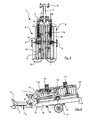
- a mower 1 according to the invention and shown in Figs. 1 to 4 has a tractor frame in the form of a T-shaped running frame 2 with a leg 3 and a crossbeam 4 in the T. At the ends of the crossbeam 4 ground wheels 5 are provided, said wheels carrying the mower 1 at least partially. At the front end of the leg 3 a connection device 6 is provided for connecting the mower 1 with a tractor (not shown) for towing and possibly also for partially carrying the mower 1.
- the mower 1 comprises two mowing aggregates 8, of which only the left one is shown in Fig. 4 , while both are shown in Figs. 1 to 3 .
- the mowing aggregates 8 are mounted on the running frame 2 substantially symmetrically about a vertical plane through the leg 3.
- each mowing aggregate 8 is mounted by a first hinge 9 with a substantially vertical axis about which the mowing aggregate 8 can swing in a horizontal plane between a working position ( Fig. 1 ) or an intermediate position ( Fig. 2 ) and a transport position ( Figs. 3 and 4 ).
- each of the mowing aggregates 8 extends laterally from the running frame 2, and in the transport position each of the mowing aggregates 8 extends rearwards, as will be explained in detail below.
- Each of the mowing aggregates 8 has a front and a rear relative to the running direction (arrow A) in the working position and comprises a frame structure 10 extending over the working width of the mowing aggregate 8.
- a beam 11 extends between a second hinge 12, which connects the beam 11 with the frame structure 10, and a third hinge 13 placed close to the first hinge 9, see Fig. 4 in particular.
- the second hinge 12 and the third hinge 13 each has a substantially horizontal hinge axis extending transversely to the beam 11. By swinging about the third hinge 13, the beam 11 can lift the mowing aggregate 8 from the ground.
- a power means is provided, such as a hydraulic cylinder, to swing the beam 11 and lift the mowing aggregate 8.
- a spring 11a is provided to act on the beam 11 in order to relieve the pressure of the mowing aggregate 8 against the ground to a desired pressure.
- the mowing aggregate 8 may adjust itself to the contour of the ground where it is uneven, in a manner known per se.
- the mowing aggregate 8 comprises cutting aggregates, not shown, in the form of a number of cutter discs mounted on a cutter bar extending in the working width transversely to the running direction A ( Fig. 1 ). Under the cutter bar, slide shoes 14 are provided which slide across the ground during operation and carry the part of the weight of the mowing aggregate not carried by the running frame 2.
- a conditioning rotor is preferably provided behind the mowing means. The rotor may be of the type which, at its ends, has screw portions which can convey material cut by the mowing means towards the centre portion of the conditioning rotor where crimping fingers are provided which crimp or condition the material and throw it to the rear.
- the mowing aggregates comprise a safety screen with side portions 15 and a safety cloth 18.
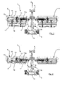
- the mowing aggregate 8 is shown in further detail in Figs. 5 and 6 and is provided with a lateral conveyor 16 arranged behind the mowing aggregate 8 and hinged to the frame structure 10 by means of two carrier arms 17. Thereby, the lateral conveyor 16 may be swung between the working position shown in Figs. 1 and 5 and the transport position shown in Figs. 2 to 4 and 6 .
- the mowing aggregate 8 with lateral conveyor is shown in an intermediate position in which the lateral conveyor 16 is in a transport position, but in which the actual mowing aggregate 8 has been swung out into a working position.
- the mowing aggregate 8 has been swung in so that it projects rearwards relative to the running direction and assumes its transport position resting on two abutments 19 on the running frame 2.
- the lateral conveyor 16 may receive material thrown by the conditioning rotor and convey it laterally towards the centre line of the mower 1 (the leg 3).
- the lateral conveyor 16 comprises a conveyor aggregate 16a, which has a conveyor belt, and which has a front edge 16b and a rear edge 16c.
- the conveyor aggregate 16a may be provided with, for example, a screw or a number of parallel rollers, as is well known in the art.
- Each carrier arm 17, of which only one is visible in Figs. 5 and 6 is hinged to the conveyor aggregate 16a at its rear edge 16c by means of a hinge connection 22 positioned between the conveyor aggregate 16 and the end of the carrier arm 17 which is connected to the frame structure 10.
- a hinge connection 22 positioned between the conveyor aggregate 16 and the end of the carrier arm 17 which is connected to the frame structure 10.
- the carrier arm 17 is divided into two members, viz. an inner member 17a and an outer member 17b.
- the carrier arm is hinged to the frame structure 10.
- the hinge connections 21, 22, 23 render it possible to swing the lateral conveyor 16 between the active working position of Fig. 5 and the passive transport position of Fig. 6 .
- the carrier arm 17 of each lateral conveyor 16 comprises an inner member 17a hinged to the frame structure 10 and an outer member 17b hinged to the inner member 17a and the conveyor aggregate 16a.
- the inner and outer members are each members of respective four-member mechanisms whereby the position of the conveyor aggregate 16a is determined relative to the position of the inner member relative to the frame structure 10. Thereby, the movement of the carrier arm 17 is fully determined as the carrier arm 17 can thus only move in one well-defined path between the two positions.
- the four-member mechanism of the inner member 17a comprises the frame structure 10 comprising a bracket 24, a parallel rod 25 which is connected to the bracket 24 by a hinge 26, and an extension 27 of the outer member 17b, which extension is connected to the parallel rod 25 by a hinge 28.
- the four-member mechanism of the outer member 17b comprises the conveyor aggregate 16a comprising a second bracket 29, a parallel arm 30 which is connected to the second bracket 29 by a hinge 31, and an extension 32 of the inner member 17a which is connected to the parallel arm 30 by a hinge 33.
- the four-member mechanisms also have the effect that the total height of the mowing aggregate 8 including the lateral conveyor in the transport position is further reduced as the outer member is folded downwards, compare Figs. 5 and 6 . Furthermore, the total distance of the carrier arm 17 from the lateral conveyor 16 in the transport position is considerably reduced compared with a mowing aggregate without hinge connections 21 and 22.
- the carrier arm 17 only comprises a single hinge connection, for example, corresponding to the hinge connection 22.
- a single hinge connection for example, corresponding to the hinge connection 22.
- a hydraulic cylinder 34 moves the carrier arm 17 and the lateral conveyor 16 between the transport position and the working position. This makes it possible in a simple and reliable way to provide the movement between the two positions of the lateral conveyor 16. Due to the four-member mechanisms 17a, 17b of the carrier arm 17, only a single hydraulic cylinder 34 is necessary to move the carrier arm 17 and the lateral conveyor 16 between the passive and the active positions.
- the mowing aggregate 8 On its front, the mowing aggregate 8 is provided, in a manner known per se, with the safety cloth 18, which is carried by a frame that can be folded up.
- the mowing aggregates 8 are carried laterally extended in the working position to mow respective paths adjacent to or overlapping the path mowed by a third mower (not shown) arranged on the front end of the tractor, not shown.
- the mowing aggregates 8 may each have a working width of, for example, 5 m or more, and in order not to exceed the maximum width for transport on public roads the front third mower may have a working width of 3 m. In many countries, 3 m is the largest permissible width of a vehicle for driving on public roads.
- the mowing aggregates 8 are lifted by means of the beams 11 and are swung rearwards about the hinges 9 to positions above the abutment 19, whereupon they are lowered to rest thereon.
- the conveyors 16 are swung to their passive position.
- the safety cloths 18 are folded up with their frames so as not to project laterally in the transport position. In this way, the transport width of the towed mower 1 is reduced to a permissible size for driving on public roads. This is obtained concurrently with a very comprehensive working width.
- the lateral conveyor 16 in the transport position, is located in its entirety behind a vertical centre plane P of the mowing aggregate 8.
- the vertical centre plane P is the plane right between the outer edges of the mowing aggregate 8 when the mowing aggregate 8 is viewed from the side as in Fig. 6 .
- these outer edges are defined by the frame structure 10 and the conveyor 16. As best seen from Fig. 3 , this provides the tractor driver with a good rearward view.
Landscapes
- Life Sciences & Earth Sciences (AREA)
- Environmental Sciences (AREA)
- Harvester Elements (AREA)
Claims (5)
- Faucheuse (1) comprenant deux groupes allongés de fauchage (8) dont chacun est articulé, par l'une des extrémités, sur un cadre d'attelage (2) pouvant être relié à un tracteur, en vue d'osciller dans un plan horizontal entre une position de travail, dans laquelle les groupes de fauchage (8) font saillie latéralement vis-à-vis d'un plan médian vertical s'étendant dans une direction de déplacement, et une position de transport dans laquelle lesdits groupes de fauchage (8) font saillie vers l'arrière par rapport à la direction de déplacement, chaque groupe de fauchage (8) offrant une structure de châssis (10) et chacun desdits groupes comprenant une partie avant et une partie arrière par rapport à la direction de déplacement, dans la position de travail, au moins l'un des groupes de fauchage (8) étant muni d'un convoyeur latéral (16) dévolu au convoyage latéral d'espèce fauchée, lequel convoyeur latéral (16) est situé derrière le groupe de fauchage (8) dans une position de travail, et lequel convoyeur latéral (16) comprend un groupe de convoyage (16a) pourvu d'un bord antérieur (16b) et d'un bord postérieur (16c), et au moins un bras de support (17) qui est relié audit groupe de convoyage (16a) sur son bord postérieur (16c) et est articulé sur la structure de châssis (10) du groupe de fauchage (8), par une liaison articulée (23), en vue d'une oscillation du convoyeur latéral (16) entre une position opérante de travail et une position inopérante de transport, caractérisée par le fait qu'elle présente une seconde liaison articulée (21, 22) interposée entre le groupe de convoyage (16a) et l'extrémité du bras de support (17) qui est reliée à la structure de châssis (10) du groupe de fauchage (8) ; et par le fait que le(s) bras de support (17) de chaque convoyeur latéral (16) comporte(nt) un élément intérieur, articulé sur ladite structure de châssis (10) dudit groupe de fauchage (8), et un élément extérieur articulé sur ledit élément intérieur et sur ledit groupe de convoyage (16a).
- Faucheuse (1) selon la revendication 1, caractérisée par le fait que le convoyeur latéral (16) comprend deux bras de support (17).
- Faucheuse (1) selon la revendication 1 ou 2, caractérisée par le fait qu'au moins l'un des éléments du bras de support (17) est un élément d'un mécanisme (17a ; 17b) comptant quatre éléments, pour commander la position du groupe de convoyage (16a) vis-à-vis de la position angulaire dudit élément du bras de support (17).
- Faucheuse (1) selon la revendication 3, caractérisée par le fait que les éléments intérieur et extérieur sont des éléments de mécanismes respectifs (17a ; 17b) comptant quatre éléments, de sorte que la position du groupe de convoyage (16a) est déterminée par rapport à la position dudit élément intérieur.
- Faucheuse (1) selon l'une quelconque des revendications 1 à 4, caractérisée par le fait que, dans la position de transport, le convoyeur latéral (16) est intégralement situé derrière un plan médian longitudinal vertical (P) du groupe de fauchage (8).
Applications Claiming Priority (1)
| Application Number | Priority Date | Filing Date | Title |
|---|---|---|---|
| DK200701400A DK200701400A (da) | 2007-09-28 | 2007-09-28 | Slåmaskine med sidetransportör |
Publications (2)
| Publication Number | Publication Date |
|---|---|
| EP2042025A1 EP2042025A1 (fr) | 2009-04-01 |
| EP2042025B1 true EP2042025B1 (fr) | 2011-04-06 |
Family
ID=40219236
Family Applications (1)
| Application Number | Title | Priority Date | Filing Date |
|---|---|---|---|
| EP08165366A Active EP2042025B1 (fr) | 2007-09-28 | 2008-09-29 | Tondeuse avec transport latéral |
Country Status (4)
| Country | Link |
|---|---|
| EP (1) | EP2042025B1 (fr) |
| AT (1) | ATE504199T1 (fr) |
| DE (1) | DE602008005978D1 (fr) |
| DK (2) | DK200701400A (fr) |
Cited By (1)
| Publication number | Priority date | Publication date | Assignee | Title |
|---|---|---|---|---|
| EP3787392A1 (fr) * | 2018-05-03 | 2021-03-10 | Kuhn SAS | Machine agricole pour la recolte de vegetaux equipee d'un convoyeur |
Families Citing this family (7)
| Publication number | Priority date | Publication date | Assignee | Title |
|---|---|---|---|---|
| DK177196B1 (da) * | 2008-04-11 | 2012-05-29 | Kongskilde Ind As | Høvender |
| DE102008062712A1 (de) * | 2008-12-18 | 2010-06-24 | Claas Saulgau Gmbh | Mähwerk mit Querfördereinrichtung |
| DE102014117583A1 (de) * | 2014-12-01 | 2016-06-02 | Claas Saulgau Gmbh | Mäheinrichtung und Verfahren zum Betreiben einer Mäheinrichtung |
| CA2961482C (fr) | 2017-03-20 | 2019-07-02 | Highline Manufacturing Ltd. | Appareil faucheur a aile pliante installee sur la barre d'outils |
| US10390488B2 (en) * | 2017-08-08 | 2019-08-27 | Deere & Company | Triplex greensmower lift system |
| AU2020347101A1 (en) * | 2019-09-12 | 2022-04-07 | Breville Pty Limited | An oven |
| GB201918843D0 (en) | 2019-12-19 | 2020-02-05 | Agco Int Gmbh | Mower combination |
Family Cites Families (7)
| Publication number | Priority date | Publication date | Assignee | Title |
|---|---|---|---|---|
| DK12690A (da) | 1990-01-16 | 1991-07-17 | Freudendahl J Fab As | Sideudkaster til en slaamaskine for graesafgroeder |
| DE19645629A1 (de) * | 1996-11-06 | 1998-05-07 | Krone Bernhard Gmbh Maschf | Heuwerbungsmaschine |
| DE10024040A1 (de) | 2000-05-16 | 2001-11-22 | Deere & Co | Schwadeinrichtung |
| DE20012446U1 (de) | 2000-07-18 | 2000-11-30 | Fella-Werke GmbH & Co. KG, 90537 Feucht | Landwirtschaftliche Maschine |
| FR2823636A1 (fr) | 2001-04-18 | 2002-10-25 | Kuhn Sa | Machine de fenaison, notamment une faucheuse avec un dispositif groupeur d'andains |
| FR2865104B1 (fr) * | 2004-01-19 | 2006-03-24 | Kuhn Sa | Faucheuse agricole munie d'un dispositif de convoyage pivotant autour d'un axe vertical |
| EP1616474B1 (fr) | 2004-07-07 | 2008-06-04 | JF-Fabriken - J. Freudendahl A/S | Faucheuse tractée comprenant un châssis et deux dispositifs de fauchage |
-
2007
- 2007-09-28 DK DK200701400A patent/DK200701400A/da not_active Application Discontinuation
-
2008
- 2008-09-29 AT AT08165366T patent/ATE504199T1/de active
- 2008-09-29 DE DE602008005978T patent/DE602008005978D1/de active Active
- 2008-09-29 EP EP08165366A patent/EP2042025B1/fr active Active
- 2008-09-29 DK DK08165366.9T patent/DK2042025T3/da active
Cited By (2)
| Publication number | Priority date | Publication date | Assignee | Title |
|---|---|---|---|---|
| EP3787392A1 (fr) * | 2018-05-03 | 2021-03-10 | Kuhn SAS | Machine agricole pour la recolte de vegetaux equipee d'un convoyeur |
| EP3787392B1 (fr) * | 2018-05-03 | 2026-04-22 | Kuhn SAS | Machine agricole pour la recolte de vegetaux equipee d'un convoyeur |
Also Published As
| Publication number | Publication date |
|---|---|
| EP2042025A1 (fr) | 2009-04-01 |
| DK2042025T3 (da) | 2011-05-16 |
| DE602008005978D1 (de) | 2011-05-19 |
| DK200701400A (da) | 2009-04-29 |
| ATE504199T1 (de) | 2011-04-15 |
Similar Documents
| Publication | Publication Date | Title |
|---|---|---|
| EP2042025B1 (fr) | Tondeuse avec transport latéral | |
| CA2429091C (fr) | Faucheuse a deux tetes de fauchage avec suspension de poutre en porte-a-faux | |
| CN100592867C (zh) | 用于切割产品的农业机器 | |
| US10076071B2 (en) | Machine for harvesting fodder | |
| RU2598916C2 (ru) | Уборочный комбайн с ножевым барабаном | |
| US8387998B2 (en) | Steering mechanism for a sugarcane harvester | |
| NL2021519B1 (nl) | Zelfrijdende landbouwmachine, bijvoorbeeld een zelfrijdende bandhark | |
| CA2323948C (fr) | Article de fauchage | |
| US20100031622A1 (en) | Self-supporting merger for mowers | |
| US20060150605A1 (en) | Vehicle for supporting a crop picking head with an adjustable suspension | |
| EP1616474B1 (fr) | Faucheuse tractée comprenant un châssis et deux dispositifs de fauchage | |
| US20150319928A1 (en) | Device for harvesting long agricultural products and agricultural self-propelled unit for harvesting agricultural products comprising the device | |
| DK2591653T4 (en) | hay-making machine | |
| EA009430B1 (ru) | Самоходная сельскохозяйственная уборочная машина | |
| EP2042023B1 (fr) | Tondeuse avec courroie de transport | |
| US7712295B2 (en) | Agricultural machine comprising a motor vehicle and several working units intended to cut plant products | |
| US7610741B2 (en) | Mower with foldable mowing units | |
| US7165384B1 (en) | Crop picking head with road travel support device | |
| DK2210473T3 (en) | CUTTING MACHINE WITH CROSSING TRANSPORTER | |
| EP0672336B1 (fr) | Faucheuse | |
| DK2526751T3 (en) | mower | |
| EP0710067A1 (fr) | Tondeuse | |
| CA2530109C (fr) | Tete recolteuse a support pour voyage sur la route | |
| NL8602334A (nl) | Voertuig voorzien van voorwielbesturing en een pendelende maai-inrichting. | |
| JPS624087B2 (fr) |
Legal Events
| Date | Code | Title | Description |
|---|---|---|---|
| PUAI | Public reference made under article 153(3) epc to a published international application that has entered the european phase |
Free format text: ORIGINAL CODE: 0009012 |
|
| AK | Designated contracting states |
Kind code of ref document: A1 Designated state(s): AT BE BG CH CY CZ DE DK EE ES FI FR GB GR HR HU IE IS IT LI LT LU LV MC MT NL NO PL PT RO SE SI SK TR |
|
| AX | Request for extension of the european patent |
Extension state: AL BA MK RS |
|
| 17P | Request for examination filed |
Effective date: 20090929 |
|
| AKX | Designation fees paid |
Designated state(s): AT BE BG CH CY CZ DE DK EE ES FI FR GB GR HR HU IE IS IT LI LT LU LV MC MT NL NO PL PT RO SE SI SK TR |
|
| GRAP | Despatch of communication of intention to grant a patent |
Free format text: ORIGINAL CODE: EPIDOSNIGR1 |
|
| GRAS | Grant fee paid |
Free format text: ORIGINAL CODE: EPIDOSNIGR3 |
|
| GRAA | (expected) grant |
Free format text: ORIGINAL CODE: 0009210 |
|
| AK | Designated contracting states |
Kind code of ref document: B1 Designated state(s): AT BE BG CH CY CZ DE DK EE ES FI FR GB GR HR HU IE IS IT LI LT LU LV MC MT NL NO PL PT RO SE SI SK TR |
|
| REG | Reference to a national code |
Ref country code: GB Ref legal event code: FG4D |
|
| REG | Reference to a national code |
Ref country code: CH Ref legal event code: EP |
|
| REG | Reference to a national code |
Ref country code: IE Ref legal event code: FG4D |
|
| REG | Reference to a national code |
Ref country code: DK Ref legal event code: T3 |
|
| REF | Corresponds to: |
Ref document number: 602008005978 Country of ref document: DE Date of ref document: 20110519 Kind code of ref document: P |
|
| REG | Reference to a national code |
Ref country code: DE Ref legal event code: R096 Ref document number: 602008005978 Country of ref document: DE Effective date: 20110519 |
|
| REG | Reference to a national code |
Ref country code: SE Ref legal event code: TRGR |
|
| REG | Reference to a national code |
Ref country code: NL Ref legal event code: T3 |
|
| PG25 | Lapsed in a contracting state [announced via postgrant information from national office to epo] |
Ref country code: SI Free format text: LAPSE BECAUSE OF FAILURE TO SUBMIT A TRANSLATION OF THE DESCRIPTION OR TO PAY THE FEE WITHIN THE PRESCRIBED TIME-LIMIT Effective date: 20110406 |
|
| LTIE | Lt: invalidation of european patent or patent extension |
Effective date: 20110406 |
|
| PG25 | Lapsed in a contracting state [announced via postgrant information from national office to epo] |
Ref country code: HR Free format text: LAPSE BECAUSE OF FAILURE TO SUBMIT A TRANSLATION OF THE DESCRIPTION OR TO PAY THE FEE WITHIN THE PRESCRIBED TIME-LIMIT Effective date: 20110406 Ref country code: NO Free format text: LAPSE BECAUSE OF FAILURE TO SUBMIT A TRANSLATION OF THE DESCRIPTION OR TO PAY THE FEE WITHIN THE PRESCRIBED TIME-LIMIT Effective date: 20110706 Ref country code: PT Free format text: LAPSE BECAUSE OF FAILURE TO SUBMIT A TRANSLATION OF THE DESCRIPTION OR TO PAY THE FEE WITHIN THE PRESCRIBED TIME-LIMIT Effective date: 20110808 Ref country code: LT Free format text: LAPSE BECAUSE OF FAILURE TO SUBMIT A TRANSLATION OF THE DESCRIPTION OR TO PAY THE FEE WITHIN THE PRESCRIBED TIME-LIMIT Effective date: 20110406 |
|
| PG25 | Lapsed in a contracting state [announced via postgrant information from national office to epo] |
Ref country code: LV Free format text: LAPSE BECAUSE OF FAILURE TO SUBMIT A TRANSLATION OF THE DESCRIPTION OR TO PAY THE FEE WITHIN THE PRESCRIBED TIME-LIMIT Effective date: 20110406 Ref country code: CY Free format text: LAPSE BECAUSE OF FAILURE TO SUBMIT A TRANSLATION OF THE DESCRIPTION OR TO PAY THE FEE WITHIN THE PRESCRIBED TIME-LIMIT Effective date: 20110406 Ref country code: GR Free format text: LAPSE BECAUSE OF FAILURE TO SUBMIT A TRANSLATION OF THE DESCRIPTION OR TO PAY THE FEE WITHIN THE PRESCRIBED TIME-LIMIT Effective date: 20110707 Ref country code: BE Free format text: LAPSE BECAUSE OF FAILURE TO SUBMIT A TRANSLATION OF THE DESCRIPTION OR TO PAY THE FEE WITHIN THE PRESCRIBED TIME-LIMIT Effective date: 20110406 Ref country code: ES Free format text: LAPSE BECAUSE OF FAILURE TO SUBMIT A TRANSLATION OF THE DESCRIPTION OR TO PAY THE FEE WITHIN THE PRESCRIBED TIME-LIMIT Effective date: 20110717 Ref country code: IS Free format text: LAPSE BECAUSE OF FAILURE TO SUBMIT A TRANSLATION OF THE DESCRIPTION OR TO PAY THE FEE WITHIN THE PRESCRIBED TIME-LIMIT Effective date: 20110806 Ref country code: FI Free format text: LAPSE BECAUSE OF FAILURE TO SUBMIT A TRANSLATION OF THE DESCRIPTION OR TO PAY THE FEE WITHIN THE PRESCRIBED TIME-LIMIT Effective date: 20110406 |
|
| REG | Reference to a national code |
Ref country code: NL Ref legal event code: TD Effective date: 20111228 Ref country code: NL Ref legal event code: SD Effective date: 20111228 |
|
| PG25 | Lapsed in a contracting state [announced via postgrant information from national office to epo] |
Ref country code: EE Free format text: LAPSE BECAUSE OF FAILURE TO SUBMIT A TRANSLATION OF THE DESCRIPTION OR TO PAY THE FEE WITHIN THE PRESCRIBED TIME-LIMIT Effective date: 20110406 Ref country code: CZ Free format text: LAPSE BECAUSE OF FAILURE TO SUBMIT A TRANSLATION OF THE DESCRIPTION OR TO PAY THE FEE WITHIN THE PRESCRIBED TIME-LIMIT Effective date: 20110406 |
|
| REG | Reference to a national code |
Ref country code: DE Ref legal event code: R082 Ref document number: 602008005978 Country of ref document: DE Representative=s name: KSNH PATENTANWAELTE KLUNKER & KOLLEGEN, DE |
|
| RAP2 | Party data changed (patent owner data changed or rights of a patent transferred) |
Owner name: KONGSKILDE INDUSTRIES A/S |
|
| PLBE | No opposition filed within time limit |
Free format text: ORIGINAL CODE: 0009261 |
|
| STAA | Information on the status of an ep patent application or granted ep patent |
Free format text: STATUS: NO OPPOSITION FILED WITHIN TIME LIMIT |
|
| PG25 | Lapsed in a contracting state [announced via postgrant information from national office to epo] |
Ref country code: RO Free format text: LAPSE BECAUSE OF FAILURE TO SUBMIT A TRANSLATION OF THE DESCRIPTION OR TO PAY THE FEE WITHIN THE PRESCRIBED TIME-LIMIT Effective date: 20110406 Ref country code: PL Free format text: LAPSE BECAUSE OF FAILURE TO SUBMIT A TRANSLATION OF THE DESCRIPTION OR TO PAY THE FEE WITHIN THE PRESCRIBED TIME-LIMIT Effective date: 20110406 Ref country code: SK Free format text: LAPSE BECAUSE OF FAILURE TO SUBMIT A TRANSLATION OF THE DESCRIPTION OR TO PAY THE FEE WITHIN THE PRESCRIBED TIME-LIMIT Effective date: 20110406 |
|
| 26N | No opposition filed |
Effective date: 20120110 |
|
| REG | Reference to a national code |
Ref country code: DE Ref legal event code: R082 Ref document number: 602008005978 Country of ref document: DE Representative=s name: KSNH PATENTANWAELTE KLUNKER/SCHMITT-NILSON/HIR, DE Effective date: 20120201 Ref country code: DE Ref legal event code: R081 Ref document number: 602008005978 Country of ref document: DE Owner name: KONGSKILDE INDUSTRIES A/S, DK Free format text: FORMER OWNER: JF-FABRIKEN - J. FREUDENDAHL A/S, SOENDERBORG, DK Effective date: 20120201 Ref country code: DE Ref legal event code: R082 Ref document number: 602008005978 Country of ref document: DE Representative=s name: SCHMITT-NILSON SCHRAUD WAIBEL WOHLFROM PATENTA, DE Effective date: 20120201 Ref country code: DE Ref legal event code: R081 Ref document number: 602008005978 Country of ref document: DE Owner name: CNH INDUSTRIAL DANMARK A/S, DK Free format text: FORMER OWNER: JF-FABRIKEN - J. FREUDENDAHL A/S, SOENDERBORG, DK Effective date: 20120201 |
|
| REG | Reference to a national code |
Ref country code: FR Ref legal event code: TP Owner name: KONGSKILDE INDUSTRIES A/S, DK Effective date: 20120217 |
|
| PG25 | Lapsed in a contracting state [announced via postgrant information from national office to epo] |
Ref country code: MC Free format text: LAPSE BECAUSE OF NON-PAYMENT OF DUE FEES Effective date: 20110930 |
|
| REG | Reference to a national code |
Ref country code: DE Ref legal event code: R097 Ref document number: 602008005978 Country of ref document: DE Effective date: 20120110 |
|
| REG | Reference to a national code |
Ref country code: GB Ref legal event code: 732E Free format text: REGISTERED BETWEEN 20120510 AND 20120516 |
|
| REG | Reference to a national code |
Ref country code: IE Ref legal event code: MM4A |
|
| PG25 | Lapsed in a contracting state [announced via postgrant information from national office to epo] |
Ref country code: IE Free format text: LAPSE BECAUSE OF NON-PAYMENT OF DUE FEES Effective date: 20110929 |
|
| REG | Reference to a national code |
Ref country code: AT Ref legal event code: PC Ref document number: 504199 Country of ref document: AT Kind code of ref document: T Owner name: KONGSKILDE INDUSTRIES A/S, DK Effective date: 20121017 |
|
| PG25 | Lapsed in a contracting state [announced via postgrant information from national office to epo] |
Ref country code: MT Free format text: LAPSE BECAUSE OF FAILURE TO SUBMIT A TRANSLATION OF THE DESCRIPTION OR TO PAY THE FEE WITHIN THE PRESCRIBED TIME-LIMIT Effective date: 20110406 |
|
| REG | Reference to a national code |
Ref country code: CH Ref legal event code: PL |
|
| PG25 | Lapsed in a contracting state [announced via postgrant information from national office to epo] |
Ref country code: LU Free format text: LAPSE BECAUSE OF NON-PAYMENT OF DUE FEES Effective date: 20110929 |
|
| PG25 | Lapsed in a contracting state [announced via postgrant information from national office to epo] |
Ref country code: BG Free format text: LAPSE BECAUSE OF FAILURE TO SUBMIT A TRANSLATION OF THE DESCRIPTION OR TO PAY THE FEE WITHIN THE PRESCRIBED TIME-LIMIT Effective date: 20110706 |
|
| PG25 | Lapsed in a contracting state [announced via postgrant information from national office to epo] |
Ref country code: CH Free format text: LAPSE BECAUSE OF NON-PAYMENT OF DUE FEES Effective date: 20120930 Ref country code: LI Free format text: LAPSE BECAUSE OF NON-PAYMENT OF DUE FEES Effective date: 20120930 |
|
| PG25 | Lapsed in a contracting state [announced via postgrant information from national office to epo] |
Ref country code: TR Free format text: LAPSE BECAUSE OF FAILURE TO SUBMIT A TRANSLATION OF THE DESCRIPTION OR TO PAY THE FEE WITHIN THE PRESCRIBED TIME-LIMIT Effective date: 20110406 |
|
| PG25 | Lapsed in a contracting state [announced via postgrant information from national office to epo] |
Ref country code: HU Free format text: LAPSE BECAUSE OF FAILURE TO SUBMIT A TRANSLATION OF THE DESCRIPTION OR TO PAY THE FEE WITHIN THE PRESCRIBED TIME-LIMIT Effective date: 20110406 |
|
| PG25 | Lapsed in a contracting state [announced via postgrant information from national office to epo] |
Ref country code: IT Free format text: LAPSE BECAUSE OF FAILURE TO SUBMIT A TRANSLATION OF THE DESCRIPTION OR TO PAY THE FEE WITHIN THE PRESCRIBED TIME-LIMIT Effective date: 20110406 |
|
| REG | Reference to a national code |
Ref country code: FR Ref legal event code: PLFP Year of fee payment: 8 |
|
| REG | Reference to a national code |
Ref country code: FR Ref legal event code: PLFP Year of fee payment: 9 |
|
| REG | Reference to a national code |
Ref country code: DE Ref legal event code: R081 Ref document number: 602008005978 Country of ref document: DE Owner name: CNH INDUSTRIAL DANMARK A/S, DK Free format text: FORMER OWNER: KONGSKILDE INDUSTRIES A/S, SOROE, DK Ref country code: DE Ref legal event code: R082 Ref document number: 602008005978 Country of ref document: DE Representative=s name: SCHMITT-NILSON SCHRAUD WAIBEL WOHLFROM PATENTA, DE Ref country code: DE Ref legal event code: R082 Ref document number: 602008005978 Country of ref document: DE Representative=s name: KSNH PATENTANWAELTE KLUNKER/SCHMITT-NILSON/HIR, DE |
|
| REG | Reference to a national code |
Ref country code: NL Ref legal event code: PD Owner name: CNH INDUSTRIAL DANMARK A/S; DK Free format text: DETAILS ASSIGNMENT: CHANGE OF OWNER(S), ASSIGNMENT; FORMER OWNER NAME: KONGSKILDE INDUSTRIES A/S Effective date: 20170411 |
|
| REG | Reference to a national code |
Ref country code: GB Ref legal event code: 732E Free format text: REGISTERED BETWEEN 20170601 AND 20170607 |
|
| REG | Reference to a national code |
Ref country code: DE Ref legal event code: R082 Ref document number: 602008005978 Country of ref document: DE Representative=s name: SCHMITT-NILSON SCHRAUD WAIBEL WOHLFROM PATENTA, DE |
|
| REG | Reference to a national code |
Ref country code: AT Ref legal event code: PC Ref document number: 504199 Country of ref document: AT Kind code of ref document: T Owner name: CNH INDUSTRIAL DANMARK A/S, DK Effective date: 20170704 |
|
| REG | Reference to a national code |
Ref country code: FR Ref legal event code: PLFP Year of fee payment: 10 |
|
| REG | Reference to a national code |
Ref country code: FR Ref legal event code: TP Owner name: CNH INDUSTRIAL DANMARK A/S, DK Effective date: 20170829 |
|
| REG | Reference to a national code |
Ref country code: FR Ref legal event code: PLFP Year of fee payment: 11 |
|
| PGFP | Annual fee paid to national office [announced via postgrant information from national office to epo] |
Ref country code: AT Payment date: 20190926 Year of fee payment: 12 |
|
| REG | Reference to a national code |
Ref country code: AT Ref legal event code: MM01 Ref document number: 504199 Country of ref document: AT Kind code of ref document: T Effective date: 20200929 |
|
| PG25 | Lapsed in a contracting state [announced via postgrant information from national office to epo] |
Ref country code: AT Free format text: LAPSE BECAUSE OF NON-PAYMENT OF DUE FEES Effective date: 20200929 |
|
| PGFP | Annual fee paid to national office [announced via postgrant information from national office to epo] |
Ref country code: DK Payment date: 20250924 Year of fee payment: 18 Ref country code: DE Payment date: 20250926 Year of fee payment: 18 |
|
| PGFP | Annual fee paid to national office [announced via postgrant information from national office to epo] |
Ref country code: NL Payment date: 20250925 Year of fee payment: 18 |
|
| PGFP | Annual fee paid to national office [announced via postgrant information from national office to epo] |
Ref country code: GB Payment date: 20250923 Year of fee payment: 18 |
|
| PGFP | Annual fee paid to national office [announced via postgrant information from national office to epo] |
Ref country code: FR Payment date: 20250925 Year of fee payment: 18 |
|
| PGFP | Annual fee paid to national office [announced via postgrant information from national office to epo] |
Ref country code: SE Payment date: 20250924 Year of fee payment: 18 |