EP2042044A1 - Sterilizing method and sterilizing apparatus for retorted product - Google Patents
Sterilizing method and sterilizing apparatus for retorted product Download PDFInfo
- Publication number
- EP2042044A1 EP2042044A1 EP07790535A EP07790535A EP2042044A1 EP 2042044 A1 EP2042044 A1 EP 2042044A1 EP 07790535 A EP07790535 A EP 07790535A EP 07790535 A EP07790535 A EP 07790535A EP 2042044 A1 EP2042044 A1 EP 2042044A1
- Authority
- EP
- European Patent Office
- Prior art keywords
- retort
- carriages
- drive source
- retorted products
- retorted
- Prior art date
- Legal status (The legal status is an assumption and is not a legal conclusion. Google has not performed a legal analysis and makes no representation as to the accuracy of the status listed.)
- Granted
Links
Images



Classifications
-
- A—HUMAN NECESSITIES
- A61—MEDICAL OR VETERINARY SCIENCE; HYGIENE
- A61L—METHODS OR APPARATUS FOR STERILISING MATERIALS OR OBJECTS IN GENERAL; DISINFECTION, STERILISATION OR DEODORISATION OF AIR; CHEMICAL ASPECTS OF BANDAGES, DRESSINGS, ABSORBENT PADS OR SURGICAL ARTICLES; MATERIALS FOR BANDAGES, DRESSINGS, ABSORBENT PADS OR SURGICAL ARTICLES
- A61L2/00—Disinfection or sterilisation of materials or objects, in general; Accessories therefor
- A61L2/02—Disinfection or sterilisation of materials or objects, in general; Accessories therefor using physical processes
- A61L2/04—Heat
-
- A—HUMAN NECESSITIES
- A23—FOODS OR FOODSTUFFS; TREATMENT THEREOF, NOT COVERED BY OTHER CLASSES
- A23B—PRESERVATION OF FOODS, FOODSTUFFS OR NON-ALCOHOLIC BEVERAGES; CHEMICAL RIPENING OF FRUIT OR VEGETABLES
- A23B2/00—Preservation of foods or foodstuffs, in general
- A23B2/30—Preservation of foods or foodstuffs, in general by heating materials in packages which are not progressively transported through the apparatus
-
- A—HUMAN NECESSITIES
- A23—FOODS OR FOODSTUFFS; TREATMENT THEREOF, NOT COVERED BY OTHER CLASSES
- A23B—PRESERVATION OF FOODS, FOODSTUFFS OR NON-ALCOHOLIC BEVERAGES; CHEMICAL RIPENING OF FRUIT OR VEGETABLES
- A23B2/00—Preservation of foods or foodstuffs, in general
- A23B2/30—Preservation of foods or foodstuffs, in general by heating materials in packages which are not progressively transported through the apparatus
- A23B2/37—Preservation of foods or foodstuffs, in general by heating materials in packages which are not progressively transported through the apparatus with packages moving on the spot
Definitions
- the present invention relates to a sterilizing method for retorted products in which a solid product or a highly viscous liquid food and the like is packaged in a heat-resistant packaging bag, and to a sterilizing apparatus for carrying out the sterilizing method.
- Sterilization processing of retorted products having contents such as a liquid food and the like sealed in a packaging bag made of a heat-resistant resin film and the like is carried out by heating the packaging bag in a retort with steam or hot water.
- heat transfer inside the retort during heating is poor, thereby requiring a long period of time for the product temperature in the center to reach a set temperature, while conversely causing burning or scorching of the contents as a result of the product temperature rising quickly at portions close to the surface of the bag thereby exposing the contents to a high temperature for an extended period of time.
- a sterilizing apparatus for carrying out this sterilizing method has a carriage A4 supported by means of wheels A3 on a support table A2 such as a tray provided within a retort body A1, and trays A6, housing a large number of retort foods A5 arranged in a row, are supported by being stacked in multiple layers on the carriage A4.
- the carriage A4 is coupled to a driveshaft A9 of a cranking mechanism A8 driven by a motor A7 through a shaft sealing mechanism A10 provided in the retort body A1, and when the motor A7 is driven and rotated, the driveshaft A9 reciprocates in the lengthwise direction of the retort body A1 in conjunction therewith, and the carriage A4 coupled to the driveshaft A9 slides forward and backward in the lengthwise direction of the retort body A1 within the retort body A1 together with the trays A6.
- the driveshaft of the cranking mechanism is coupled to the carriage inside the retort body through the shaft sealing mechanism provided in the retort body
- the shaft sealing mechanism employs a structure in which the driveshaft is sealed by making sliding contact with the driveshaft reciprocating in the axial direction
- this shaft sealing mechanism had problems such as the shaft sealing mechanism for maintaining sealing performance being complex.
- the driveshaft of the cranking mechanism during motor rotation reciprocates forward and backward in the axial direction thereof, it was necessary to provide space for the forward and backward stroke of the driveshaft in close proximity to the retort body.
- an object of the present invention is to overcome the problems of the prior art as described above by providing a sterilizing method and sterilizing apparatus for retorted products capable of sterilizing efficiently and uniformly without creating differences in temperature within a packaging bag and not allowing the occurrence of portions where adequate sterilization effects are unable to be obtained or portions where the contents end up scorching, facilitates unidirectional transfer of loading and unloading of retorted products to and from a retort, increases the degree of freedom of the configuration of a production line, enables a shaft sealing mechanism to be configured easily, and reduces the space occupied by the sliding portion of a carriage exposed outside the retort.
- the sterilizing method for retorted products as claimed in the present invention that achieves the above-mentioned object is a sterilizing method for retorted products, in which carriages on which retorted products are placed are slid within a retort while carrying out heat sterilization processing on the retortedproducts, wherein the driving force of a drive source installed outside the retort is transmitted to the carriages after being converted to reciprocal motion, and the carriages are slid reciprocally at a preset prescribed cycle in the forward and backward or leftward and rightward directions of the retort.
- a rotating drive source using a motor installed outside the retort, or a linear reciprocating drive source using cylinder apparatuses provided in a direction perpendicular to the lengthwise direction of the retort can be employed for the drive source in the present invention.
- the rotary motion of the rotating drive source is transmitted to the carriages after being converted to reciprocal motion by a cam mechanism, enabling the carriages to slide in the forward and backward or leftward and rightward directions of the retort.
- the linear reciprocating drive source is provided independently for each carriage, and each carriage is allowed to reciprocate independently in a horizontal direction perpendicular to the lengthwise direction.
- At least one of either the cycle or phase of the reciprocal sliding of the carriages can be varied between the carriages arranged in a row in the lengthwise direction in the retort, and the sliding pattern can be changed in accordance with the products to be sterilized by controlling the sliding frequency of the carriages during retort processing.
- the sterilizing apparatus for retorted products of the present invention for carrying out the sterilizing method described above is a sterilizing apparatus in which carriages on which retorted products are placed are slid within a retort while carrying out heat sterilization processing on the retorted products, and comprises: a plurality of carriages which are arranged in a row in the lengthwise direction in the retort, are provided so as to be able to respectively slide reciprocally in the lengthwise direction or a horizontal direction perpendicular to the lengthwise direction, and hold trays housing retorted products; and a reciprocating drive source that allows the carriages to slide reciprocally within the retort, wherein the reciprocating drive source is installed outside the retort.
- the reciprocating drive source can be a rotating drive source using a motor installed outside the retort
- a rotating driveshaft driven by the rotating drive source can be allowed to rotatably pass through a retort wall by means of a shaft sealing mechanism
- the rotating driveshaft can be driven by a cam mechanism within the retort by being coupled thereto
- the rotary motion of the rotating driveshaft can be transmitted to the carriages after being converted to reciprocal motion by the cam mechanism
- the carriages can be allowed to slide in the forward and backward or leftward and rightward directions of the retort.
- the cam mechanism can be constituted by eccentric cams rotated and driven by the rotating drive source, and cam followers attached to the carriages.
- a linear reciprocating drive source which is provided independently for each carriage and uses a plurality of cylinder mechanisms provided in a direction perpendicular to the lengthwise direction of the retort, can also be used as another reciprocating drive source.
- a reciprocating drive source that drives the carriages by varying at least one of either the cycle or phase of the reciprocal sliding between the carriages arranged in a row in the lengthwise direction in the retort can be employed for either of the reciprocating drive sources.
- the reciprocating drive source can be controlled by switching on and off and by varying speed during retort processing, and the sliding pattern can also be changed in accordance with the products to be sterilized by controlling the frequency of the drive source of the carriages during retort processing.
- doors can be provided in the front and back of the retort enabling loading and unloading of retorted products to be carried out in a single direction, thereby enabling a high degree of freedom in the configuration of a production line containing a retort sterilization step.
- unidirectional transfer can be carried out easily in which unprocessed retorted products are loaded from one end of the retort and unloaded from the other end following completion of sterilization, which together with preventing unsterilized products from entering the packaging step, enables the cycle time of the sterilization processing step to be shortened.
- a rotating drive source such as a motor or a linear reciprocating drive source such as a cylinder apparatus installed outside the retort after being converted to reciprocal motion
- a cranking mechanism only the motor or cylinder apparatus is required to be installed outside the retort, thereby making it possible to reduce the total installation space of the apparatus while also reducing noise and vibrations generated during apparatus operation.
- the use of a cam mechanism or linear drive mechanism makes it possible to increase the degree of freedom when selecting the installation site of the rotating drive mechanism. Since sterilization time can be shortened according to the present invention, in addition to improving productivity, steam, hot water, water and electrical utility costs can be reduced thereby making it possible to decrease running costs. In addition, since the time during which products are exposed to high temperatures is shortened, thermal deterioration of the contents is prevented, thereby improving color and flavor after retorting.
- a plurality of carriages can also be made to slide individually by respective and independent drive sources, and in this case, the inertia of the tray carriages decreases enabling compact and low output power sources to be used for the power sources, thereby making it possible to reduce vibrations generated during operation.
- vibrations generated due to sliding of the carriages can be more effectively reduced.
- the sliding pattern of the carriages can be changed arbitrarily in accordance with the products to be sterilized by controlling the frequency of the drive source of the carriages during retort processing, the sliding pattern can be arbitrarily selected even during sterilization, and by sliding at the maximum frequency when the ambient temperature has reached the sterilization temperature by changing the sliding frequency when raising the ambient temperature, sterilizing or lowering the ambient temperature, for example, product temperature can be controlled, thereby enabling retort processing while always sliding under the optimum conditions in accordance with the type of product to be sterilized in terms of contents, size and the like.
- the sliding pattern can be changed easily in accordance with the type of product to be sterilized by selecting the optimum pattern and presetting that pattern in the apparatus for each product to be sterilized.
- the service life of the retorting apparatus itself is extended.
- two-dimensional sliding is carried out in combination with sliding in the lengthwise direction of the carriers, agitation effects on the contents in the return path are increased, thereby making it possible to further expect the effect of shortening the sterilization time of highly viscous products and products in large bags for commercial use.
- a sterilizing apparatus 1A of the present embodiment has a retort 3 held with support legs 2 on a floor surface.
- the retort 3 is constituted by a cylindrical retort body 3A and covers 3B and 3C attached to the ends on the front and back in the lengthwise direction thereof.
- a sterilizing apparatus 1 is arranged an intermediate point of a transfer line in a factory not shown with the lengthwise direction of the retort 3 facing in the direction of transfer of the transfer line.
- the front and back covers 3B and 3C are each able to be opened and closed, and retorted products not yet sterilized that have been transferred from a previous line with the transfer line are able to be loaded into the retort body 3A by opening the back cover 3B (cover on the upstream side of the direction of transfer, or in other words, the loading side).
- retorted products on which sterilization processing with the sterilizing apparatus 1 has been completed can be unloaded to the downstream side of the transfer line and transferred to the next step by the transfer line by opening the front cover 3C (cover on the downstream side in the direction of transfer, or in other words the unloading side).
- loading of unprocessed retorted products into the retort body 3A of the sterilizing apparatus 1 and unloading of processed retorted products from the retort body 3A can be carried out simultaneously by opening the cover 3B and the cover 3C, and when loading of all unprocessed retorted products into the retort body 3A has been completed, the covers 3B and 3C are closed followed by carrying out sterilization processing of the retorted products by the sterilizing apparatus 1.
- an interlock control can be provided that only starts loading of unprocessed products after cover 3B has been closed following transfer of sterilized trays.
- a large number of retorted products 4, which have been loaded into the retort body 3A by a conveyor of the transfer line, are respectively housed in rows on trays 5 stacked in a plurality of layers, and these stacked trays 5 are removably coupled and fixed by a fixing tool not shown so that the stacks thereof do not collapse. Furthermore, these trays 5 are omitted from FIG. 1 .
- These retorted products 4 have contents sealed in a packaging bag comprising lamination of a heat-resistant synthetic resin and aluminum foil, are inserted one at a time between a large number of dividers provided on the trays 5, and are arranged in rows so as not to shift out of position or fall outside the trays 5 even during vibration of the trays 5.
- the lower surfaces in the vicinity of the side edges on both the left and right sides of the lowermost trays 5 stacked in a plurality of layers within the retort body 3A are supported by a plurality of tray holding rollers 6 provided in two rows to the left and right in the lower portion of the retort body 3A. Both ends of these tray holding rollers 6 are rotatably supported with bearings by roller support frames 7A comprising a portion of carriages 7 provided in the lower portion of the retort body 3A, and the trays 5 stacked in a plurality of layers are able to move within the retort body 3A in the lengthwise direction thereof by the rotation of these tray holding rollers 6.
- each of these roller support frames 7A is set to be roughly equal to the length of one side of the trays 5 along the lengthwise direction of the retort body 3A, and groups of the trays 5 stacked in a plurality of layers are placed so as to span pairs of roller support frames 7A on the left and right sides.
- stopper mechanisms are provided in the vicinity of the ends of each of the roller support frames 7A on the left and right sides in opposition to the lengthwise direction thereof in order to restrict the movement of the groups of trays 5 placed on the tray holding rollers 6, enabling groups of trays 5 to be fixed in position on the left and right pairs of roller support frames 7Aduring sterilizationprocessing and the like of the retorted products 4.
- the lower surfaces of the roller support frames 7A comprising the carriages 7 are supported on a plurality of rows of carriage holding rollers 9 fixed to the inside and bottom of the retort body 3 and respectively and rotatably supported with bearings by pairs of roller support frames 8 on the left and right sides, and the carriages 7 are able to move freely within a prescribed range in the lengthwise direction of the retort body 3Aby allowing these carriage holding rollers 8 to rotate freely.
- pairs of left and right cam followers 10 are attached to the carriages 7. Pairs of cam guide surfaces 10A respectively arranged in a row to the front and back in the perpendicular direction as shown in FIG. 3 are formed in these cam followers 10, and eccentric cams 11 are respectively arranged between these cam guide surfaces 10A. These eccentric cams 11 are fixed to a rotating driveshaft 12 rotatably supported with bearings in the lower portion of the retort body 3A in an orientation that transverses to the left and right the lengthwise direction of the retort body 3A.
- the rotating driveshaft 12 protrudes outside the retort body 3A by passing through the inside of a shaft sealing mechanism 13, and is coupled by a shaft joint 14 to an output shaft of a rotating drive source in the form of a motor 16 fixed on a mounting bracket 15 provided on the side of the support leg 2.
- the shaft sealing mechanism 13 employs a structure in which the periphery of the rotating driveshaft 12 is rotatably sealed with a gasket sealing member so that high-temperature and high-pressure steam within the retort body 3A does not escape to the outside during sterilization processing. Furthermore, in the present embodiment, a cam mechanism of the present invention is composed by the cam followers 10 and the eccentric cams 11.
- Unsterilized retorted products 4 are housed in the trays 5 stacked in a plurality of layer and carried to just in front of the retort 3 by a conveyor of a transfer line not shown where they are temporarily stopped and paused.
- the cover 3B of the retort 3 is opened, and a group of the trays 5 stacked in a plurality of layers is transferred onto the tray holding rollers 6 within the retort body 3A from the conveyor of the transfer line.
- each of the tray holding rollers 6 may be synchronously driven collectively for each group of left and right pairs of the roller support frames 7A by a drive source such as a motor not shown.
- a means for moving the trays 5 stacked in a plurality of layers within the retort body 3A is not limited to the tray holding rollers 6 driven by a motor and the like, but rather a pushing mechanism can be used that is arranged between the rows of tray holding rollers 6 on both the left and right sides and uses pusher dogs driven with cylinder apparatuses and the like, and the pusher dogs may be made to engage with the lowermost trays 5 so as to push the trays 5 stacked in a plurality of layers forward at a prescribed stroke interval.
- each lowermost tray 5 is held in position so as not to move forward or backward (lengthwise direction of the retort 3) by a stopper mechanism not shown as a result of being detected by a detection means not shown.
- the back cover 3B is closed and heat sterilization processing of the retorted products 4 begins within the retort 3.
- the motor 16 provided outside the retort 3 is driven.
- the rotating driveshaft 12 rotates and the eccentric cam 11s are driven and rotated.
- the carriages 7 fixed thereto also slide in the forward and backward directions of the retort body 3A.
- the groups of trays 5 Since the movement of the groups of trays 5 stacked in a plurality of layers placed on the carriages 7 is restricted on the carriages 7 by the stopper mechanism described above, the groups of trays 5 also slide together with the carriages 7.
- the contents of the retorted products 4 housed therein slide within the packaging bags, and as a result thereof, the contents are subjected to agitation effects and temperature unevenness within the packaging bags is reduced, thereby allowing the contents to be sterilized in a short period of time while also making it possible to avoid partially incomplete sterilization and scorching caused by overheating.
- groups of trays (not shown) housing unprocessed retorted products 4, which have been transferred from the previous step and which are stacked in a plurality of layers and waiting on a conveyor of a transfer line, are sequentially loaded from the side of the back cover 3B into the retort body 3A, and once all of these groups of trays have been loaded into the retort body 3A, the front and back covers 3B and 3C are closed and the previously described processed is repeated.
- the cycle time of the sterilization processing step can be shortened.
- FIG. 4 is a perspective view showing another embodiment of the retorted product sterilizing apparatus as claimed in the present invention.
- An outline of the contour of the retort body 3A in a sterilizing apparatus 1B is indicated with a virtual line in FIG. 4 .
- a rotating driveshaft 12A of a motor 16A provided outside the retort body 3A is drivingly coupled to a rotating driveshaft 12B extending in the lengthwise direction of the retort body 3A through a gear box 17 provided on the upper end of a support leg 2A that supports the retort body 3A, and is further drivingly coupled to a rotating driveshaft 12C, the orientation of the rotation axis line thereof being perpendicular to the rotating driveshaft 12B, through a gear box 18 provided on the upper end of an adjacent support leg 2A.
- the gear box 18 is provided at a plurality of locations along the forward and backward directions (lengthwise direction) of the retort body 3A, and the rotating driveshaft 12C to which the eccentric cam 11 is provided at a plurality of locations corresponding to each of the gear boxes 18.
- the left and right pairs of roller support frames 7A on which the tray holding rollers 6 are arranged are provided in a plurality of groups of rows in the lengthwise direction of the retort body 3A in the same manner as shown in FIG. 1 although not shown in FIG. 4 , and each group of the left and right pairs of roller support frames 7A is collectively slid in the forward and backward directions of the retort body 3A by the eccentric cams 11 fixed on the rotating driveshafts 12C provided corresponding thereto.
- free-rolling rollers not having a drive source are used for the tray holding rollers 6, and a relay carriage 21, guided by traveling guide wheels 20 on a pair of left and right guide rails 19 provided on the bottom inside the retort body 3A between the left and right roller support frames 7A, is used for loading and unloading the trays 5 stacked in a plurality of layers.
- the relay carriage 21 is provided with a pair of dogs 22 that removably retain the front and back ends of the lowermost tray 5 stacked in a plurality of layers by clamping from the forward and backward directions in the vicinity of both ends in the forward and backward directions of the upper surface thereof, and is able to move reciprocally between the inside of the retort body 3A and roller conveyors 23 installed outside the retort body 3A.
- the trays 5 stacked in a plurality of layers are housed inside the retort body 3A by being supported in order by left and right transfer rollers 23A provided on the roller conveyors 23, relay rollers 24 and the tray holding rollers 6, and by being pushed by the relay carriage 21. Furthermore, the pair of dogs 22 are comprised to be erected and collapsed by a drive means not shown installed on the relay carriage 21.
- the groups of trays 5 housed in the retort body 3A are held in position at a prescribed location with their forward and backward movement relative to the roller support frames 7A being restricted by stoppers 27 driven to advance and retract from both sides above the tray holding rollers 6 by actuators 26 attached at the front and back thereof on the side of the roller support frames 7A.
- the stoppers 27 and the actuators 26, which cause them to advance and retract are respectively provided on the front and back ends of the pair of left and right roller support frames 7A.
- the travel thereof is guided by a pair of guide rails having the same structure as the guide rails 19 respectively provided on the insides of the rows of the left and right transfer rollers 23A, and when leaving and entering the retort body 3A, are guided by guides having the same cross-sectional shape as the guide rails 19 respectively formed on a pair of left and right relay frames 25, thereby enabling the relay carriage 21 to transfer to the side of the guide rails 19.
- an endless or fluid cylinder apparatus such as a chain or timing belt is used to drive the reciprocating travel of the relay carriage 21, and can be carried out by a drive means equipped with a drive source on the side of the relay carriage 21.
- each motor 16A can be dispersed if the gear box 17 driven and coupled to the motor 16A is arranged at a plurality of locations and a common rotating driveshaft 12B is driven by a plurality of the motors 16A, a small motor can be used for the rotating drive source.
- an eccentric cam mechanism is used as a cam mechanism to slide carriages in the forward and backward directions of a retort in the embodiments explained above
- a structure can also be employed in which a cylindrical cammechanism, for example, is used as a cam mechanism, cam followers are guided in cam grooves formed in the peripheral surfaces of cylindrical cams and the cam followers can be allowed to move reciprocally in the axial direction of the cylindrical cams, and sterilization processing can be carried out while allowing retorted products to slide in the leftward and rightward directions relative to the retort body by supporting the carriages to as to be able to move in the leftward and rightward directions of the retort body.
- FIGS. 6 and 7 show a sterilizing apparatus for retorted products as claimed in another embodiment of the present invention.
- drive sources for sliding carriages reciprocally are linear reciprocating drive sources provided independently for each carriage and provided perpendicular to the lengthwise direction of the retort, and the carriages are independently slid in a horizontal direction perpendicular to the lengthwise direction by the linear reciprocating drive sources.
- a sterilizing apparatus 1C for retortedproducts of the present embodiment eight carriers 7 within the retort 3 are supported on carriage holding rollers 8 provided in two rows each in the horizontal direction perpendicular to the lengthwise direction of the retort body 3A.
- These carriage holding rollers 30 are rotatably supported on both ends with bearings by roller holding frames 31 attached to both the left and right sides at the lower portion of the inner periphery of the retort body 3A, and each of the carriages 7 is able to move freely in the horizontal direction perpendicular to the lengthwise direction of the retort body 3A within the retort body 3A by allowing these carriage holding rollers 30 to rotate freely.
- a coupling rod 36 which passes through the peripheral wall of the retort body 3A, is coupled to each carriage 7 through a sealing mechanism 35 that isolates the inside and outside of the retort 3 as shown in FIG. 6 .
- the other end of the coupling rod 36 is coupled to a drive rod 38A provided in a drive source in the form of an air cylinder mechanism 38 attached to a support arm 37 provided protruding from the outer peripheral surface of the retort 3.
- the air cylinder mechanism 38 is provided in a quantity equal to the number of carriages 7, and in the present embodiment, a total of eight of the air cylinder mechanisms 38 are provided, and each is driven and controlled by a drive control mechanism not shown.
- the driving rods 38A of the air cylinder mechanisms 38 are repeatedly driven to advance and retract at a prescribed cycle and stroke in the horizontal direction perpendicular to the lengthwise direction of the retort 3, the movement of the driving rods 38A is transmitted to the carriages 7 through the coupling rods 36, and the carriages 7 are configured so as to slide in the same direction as the driving rods 38A while being supported by the carriage holding rollers 30.
- two groups of carriages 7, respectively supporting the lower surfaces of the lowermost tray 5 of each group of trays 5 stacked in a plurality of layers at both the left and right sides, are driven and controlled in coordination with the air cylinder mechanisms 38 that drive each carriage 7 so that the carriages 7 move at mutually the same amplitude, in the same phase and in synchronization.
- two of these carriages 7 may be configured in the form of an integral member by coupling together, and in this case, these integral carriages 7 may be driven using a drive source such as a single air cylinder mechanism.
- a drive source such as a single air cylinder mechanism.
- the drive source for sliding the carriages is not limited to the air cylinder mechanism, but rather a rotating drive source in the manner of a motor, for example, may be used so as to slide the carriages by means of a cranking mechanism.
- the sterilizing apparatus 1 of the present embodiment may be equipped with drive control apparatuses that allow the cycle and phase of reciprocal motion of the drive rods to be individually set for each of four groups consisting of left and right pairs each of the eight air cylinder mechanisms 38 provided on both sides outside the retort 3.
- the contents of the retorted products 4 housed therein slide within the packaging bags.
- the temperature of the contents is uniform throughout the entire inside of the packaging bags due to agitation effects, thereby avoiding partially incomplete sterilization and scorching caused by over heating.
- theagitationeffects on the contents also enable the sterilization time to be shortened.
- the sliding cycles and sliding phases of the groups P1, P2, P3 and P4 of the trays 5 can be changed individually, varying these sliding cycles and sliding phases enables resonance of the overall sterilizing apparatus 1C to be suppressed, thereby making it possible to reduce the effects of vibrations and noise on the area around the sterilizing apparatus 1C.
- the retorted products 4 continue to undergo cooling processing while sliding the groups P1, P2, P3 and P4 of the trays 5 for a short time thereafter. Cooling the groups P1, P2, P3 and P4 of the trays 5 while sliding in this manner makes it possible to shorten the amount of time required for cooling.
- FIGS. 7 to 10 are graphs showing measurement results when sterilization processing tests were carried out by sliding retorted products at various frequencies, the retorted products used for measurement consisted of 1 kg packages of curry soup, the sterilization temperature within the retort was 120°C, come-up time was 12 minutes, sterilization advances to the next step at a sterilization value in the form of an Fo value of 5, and the sliding stroke of the retorted products was 75 mm.
- advancing to the next step refers to advancing from the retorted product sterilization step to the cooling step, and here, advancing to the next step at an Fo value of 5 means that the sterilization step advances to the cooling step when the Fo value of the retorted products has reached 5.
- the graph of FIG. 7 shows the results of carrying out sterilization processing while sliding the retorted products at a sliding frequency of 30 Hz, and in this example, the amount of time from the start of sterilization until the Fo value reaches 5 was 31 minutes 10 seconds, the amount of time from the start of sterilization until the product temperature has decreased to 50°C after entering the cooling step following heating was 50 minutes 12 seconds, and the final Fo value was 8.19.
- the graph of FIG. 8 shows the results of carrying out sterilization processing while sliding the retorted products at a sliding frequency of 35 Hz, and in this example, the amount of time from the start of sterilization until the Fo value reaches 5 was 28 minutes 01 second, the amount of time from the start of sterilization until the product temperature has decreased to 50°C after entering the cooling step following heating was 45 minutes 46 seconds, and the final Fo value was 7.77.
- the graph of FIG. 9 shows the results of carrying out sterilization processing while sliding the retorted products at a sliding frequency of 40 Hz, and in this example, the amount of time from the start of sterilization until the Fo value reaches 5 was 23 minutes 52 seconds, the amount of time from the start of sterilization until the product temperature has decreased to 50°C after entering the cooling step following heating was 36 minutes 20 seconds, and the final Fo value was 6.82.
- the graph of FIG. 10 shows the results of carrying out sterilization processing while sliding the retorted products at a sliding frequency of 45 Hz, and in this example, the amount of time from the start of sterilization until the Fo value reaches 5 was 22 minutes 42 seconds, the amount of time from the start of sterilization until the product temperature has decreased to 50°C after entering the cooling step following heating was 34 minutes 17 seconds, and the final Fo value was 6.75.
- the amount of time from the start of sterilization until the Fo value reaches 5 was 110 minutes
- the amount of time from the start of sterilization until the product temperature has decreased to 50°C after entering the cooling step following heating was 2 hours 45 minutes
- the final Fo value was 7.
- observation of the status of the retorted products following sterilization revealed the presence of portions in which the contents were partially scorched, or in other words, portions in which so-called "retort browning" occurred.
- sterilization time was confirmed to be able to be shortened considerably as compared with conventional methods, and the contents of retorted products were confirmed to be able to be uniformly sterilized without the occurrence of scorched portions or portions that escaped sterilization.
- the motor serving as a rotating drive source during retort operation can be switched on and off and the speed thereof can be controlled as desired, and the sliding frequency of the carriages during retort processing can be controlled as desired by switching on and off and freely controlling the speed of motor.
- the contents to be sterilized are susceptible to separation of an oil fraction or susceptible to foaming, there are cases in which it is desirable to not slide the contents as much as possible. In such cases, sterilization can be carried out efficiently and uniformly without having an effect on the contents by holding sliding to the absolute minimum.
- FIG. 11 shows an example of the case of changing the sliding pattern by controlling the sliding frequency of the carriages during retort operation to the optimum frequency according to the ambient temperature.
- the pattern used for sterilization processing consists of not sliding the carriages until the ambient temperature following the start of processing reaches 80°C (namely, sliding frequency of 0 Hz with the motor switched off), sliding the carriages at 30 Hz until the sterilization temperature rises from 80°C to the sterilization temperature of 120°C, sliding at 45 Hz during sterilization, lowering the sliding frequency to 35 Hz following completion of sterilization until the temperature falls to 80°C in the cooling step, and then discontinuing sliding when the ambient temperature has fallen to 80°C.
- product temperature can be controlled by arbitrarily changing the sliding pattern during processing in this manner, retort processing can be carried out under the optimum conditions at all times without causing excessive sliding simply by presetting the pattern in accordance with the type of product to be sterilized by determining the optimum sliding pattern in advance for each type or size of product to be sterilized and then storing that pattern in a controller in the form of a program.
- changing the sliding pattern was carried out according to ambient temperature in the example above, the sliding frequency can also be changed according to product temperature by monitoring product temperatures of products to be sterilized, for example.
- the sterilizing method and sterilizing apparatus for retorted products of the present invention can be used to sterilize retorted products having foods or pharmaceuticals and the like sealed inside, and are particularly preferable for retorted products in which solid products or highly viscous contents are sealed in a packaging bag and the like and which use a large or thick packaging bag.
Landscapes
- Life Sciences & Earth Sciences (AREA)
- Engineering & Computer Science (AREA)
- Wood Science & Technology (AREA)
- Zoology (AREA)
- Chemical & Material Sciences (AREA)
- Food Science & Technology (AREA)
- Polymers & Plastics (AREA)
- Health & Medical Sciences (AREA)
- Epidemiology (AREA)
- Animal Behavior & Ethology (AREA)
- General Health & Medical Sciences (AREA)
- Public Health (AREA)
- Veterinary Medicine (AREA)
- Food Preservation Except Freezing, Refrigeration, And Drying (AREA)
Abstract
Description
- The present invention relates to a sterilizing method for retorted products in which a solid product or a highly viscous liquid food and the like is packaged in a heat-resistant packaging bag, and to a sterilizing apparatus for carrying out the sterilizing method.
- Sterilization processing of retorted products having contents such as a liquid food and the like sealed in a packaging bag made of a heat-resistant resin film and the like is carried out by heating the packaging bag in a retort with steam or hot water. However, in the case of sterilization processing of retorted products having a large or thick packaging bag, or having highly viscous contents or containing solid products, heat transfer inside the retort during heating is poor, thereby requiring a long period of time for the product temperature in the center to reach a set temperature, while conversely causing burning or scorching of the contents as a result of the product temperature rising quickly at portions close to the surface of the bag thereby exposing the contents to a high temperature for an extended period of time.
- Therefore, in order to solve these problems, the present applicant proposed a sterilizing method and apparatus for sterilizing retort foods in a retort while sliding to the front and back and to the left and right followed by cooling (see Patent Document 1). As shown in
FIG. 12 , a sterilizing apparatus for carrying out this sterilizing method has a carriage A4 supported by means of wheels A3 on a support table A2 such as a tray provided within a retort body A1, and trays A6, housing a large number of retort foods A5 arranged in a row, are supported by being stacked in multiple layers on the carriage A4. - The carriage A4 is coupled to a driveshaft A9 of a cranking mechanism A8 driven by a motor A7 through a shaft sealing mechanism A10 provided in the retort body A1, and when the motor A7 is driven and rotated, the driveshaft A9 reciprocates in the lengthwise direction of the retort body A1 in conjunction therewith, and the carriage A4 coupled to the driveshaft A9 slides forward and backward in the lengthwise direction of the retort body A1 within the retort body A1 together with the trays A6.
- Patent Document 1: Japanese Patent Publication No.
S58-2666 - However, in the sterilizing apparatus described in
Patent Document 1 above, since the motor and cranking mechanism that drive the carriage are provided in close proximity to one end in the lengthwise direction of the retort body, loading and unloading of trays to and from the retort body can only be carried out from the other end, and unidirectional transfer of retort foods in the manner of loading trays housing unprocessed retort foods from one end of the retort body while unloading trays from the other end following completion of sterilization cannot be carried out, thereby placing limitations on the configuration of the retort food production line. In addition, although the driveshaft of the cranking mechanism is coupled to the carriage inside the retort body through the shaft sealing mechanism provided in the retort body, since the shaft sealing mechanism employs a structure in which the driveshaft is sealed by making sliding contact with the driveshaft reciprocating in the axial direction, this shaft sealing mechanism had problems such as the shaft sealing mechanism for maintaining sealing performance being complex. In addition, since the driveshaft of the cranking mechanism during motor rotation reciprocates forward and backward in the axial direction thereof, it was necessary to provide space for the forward and backward stroke of the driveshaft in close proximity to the retort body. - Therefore, an object of the present invention is to overcome the problems of the prior art as described above by providing a sterilizing method and sterilizing apparatus for retorted products capable of sterilizing efficiently and uniformly without creating differences in temperature within a packaging bag and not allowing the occurrence of portions where adequate sterilization effects are unable to be obtained or portions where the contents end up scorching, facilitates unidirectional transfer of loading and unloading of retorted products to and from a retort, increases the degree of freedom of the configuration of a production line, enables a shaft sealing mechanism to be configured easily, and reduces the space occupied by the sliding portion of a carriage exposed outside the retort.
- The sterilizing method for retorted products as claimed in the present invention that achieves the above-mentioned object is a sterilizing method for retorted products, in which carriages on which retorted products are placed are slid within a retort while carrying out heat sterilization processing on the retortedproducts, wherein the driving force of a drive source installed outside the retort is transmitted to the carriages after being converted to reciprocal motion, and the carriages are slid reciprocally at a preset prescribed cycle in the forward and backward or leftward and rightward directions of the retort.
- A rotating drive source using a motor installed outside the retort, or a linear reciprocating drive source using cylinder apparatuses provided in a direction perpendicular to the lengthwise direction of the retort, can be employed for the drive source in the present invention. In the case of employing a rotating drive source, the rotary motion of the rotating drive source is transmitted to the carriages after being converted to reciprocal motion by a cam mechanism, enabling the carriages to slide in the forward and backward or leftward and rightward directions of the retort. In addition, in the case of employing a linear reciprocating drive source, the linear reciprocating drive source is provided independently for each carriage, and each carriage is allowed to reciprocate independently in a horizontal direction perpendicular to the lengthwise direction.
- In the present invention, at least one of either the cycle or phase of the reciprocal sliding of the carriages can be varied between the carriages arranged in a row in the lengthwise direction in the retort, and the sliding pattern can be changed in accordance with the products to be sterilized by controlling the sliding frequency of the carriages during retort processing.
- In addition, the sterilizing apparatus for retorted products of the present invention for carrying out the sterilizing method described above is a sterilizing apparatus in which carriages on which retorted products are placed are slid within a retort while carrying out heat sterilization processing on the retorted products, and comprises: a plurality of carriages which are arranged in a row in the lengthwise direction in the retort, are provided so as to be able to respectively slide reciprocally in the lengthwise direction or a horizontal direction perpendicular to the lengthwise direction, and hold trays housing retorted products; and a reciprocating drive source that allows the carriages to slide reciprocally within the retort, wherein the reciprocating drive source is installed outside the retort.
- In the present invention, the reciprocating drive source can be a rotating drive source using a motor installed outside the retort, a rotating driveshaft driven by the rotating drive source can be allowed to rotatably pass through a retort wall by means of a shaft sealing mechanism, the rotating driveshaft can be driven by a cam mechanism within the retort by being coupled thereto, the rotary motion of the rotating driveshaft can be transmitted to the carriages after being converted to reciprocal motion by the cam mechanism, and the carriages can be allowed to slide in the forward and backward or leftward and rightward directions of the retort. The cam mechanism can be constituted by eccentric cams rotated and driven by the rotating drive source, and cam followers attached to the carriages. In addition, a linear reciprocating drive source, which is provided independently for each carriage and uses a plurality of cylinder mechanisms provided in a direction perpendicular to the lengthwise direction of the retort, can also be used as another reciprocating drive source.
- A reciprocating drive source that drives the carriages by varying at least one of either the cycle or phase of the reciprocal sliding between the carriages arranged in a row in the lengthwise direction in the retort, can be employed for either of the reciprocating drive sources. Moreover, in the sterilizing apparatus for retorted products according to the present invention, the reciprocating drive source can be controlled by switching on and off and by varying speed during retort processing, and the sliding pattern can also be changed in accordance with the products to be sterilized by controlling the frequency of the drive source of the carriages during retort processing.
- According to the present invention, since a rotating drive mechanism that slides carriages is installed outside a retort, doors can be provided in the front and back of the retort enabling loading and unloading of retorted products to be carried out in a single direction, thereby enabling a high degree of freedom in the configuration of a production line containing a retort sterilization step. As a result, unidirectional transfer can be carried out easily in which unprocessed retorted products are loaded from one end of the retort and unloaded from the other end following completion of sterilization, which together with preventing unsterilized products from entering the packaging step, enables the cycle time of the sterilization processing step to be shortened. In addition, since driving force is transmitted to the carriages by a rotating drive source such as a motor or a linear reciprocating drive source such as a cylinder apparatus installed outside the retort after being converted to reciprocal motion, in comparison with the use of a cranking mechanism, only the motor or cylinder apparatus is required to be installed outside the retort, thereby making it possible to reduce the total installation space of the apparatus while also reducing noise and vibrations generated during apparatus operation. In addition, the use of a cam mechanism or linear drive mechanism makes it possible to increase the degree of freedom when selecting the installation site of the rotating drive mechanism. Since sterilization time can be shortened according to the present invention, in addition to improving productivity, steam, hot water, water and electrical utility costs can be reduced thereby making it possible to decrease running costs. In addition, since the time during which products are exposed to high temperatures is shortened, thermal deterioration of the contents is prevented, thereby improving color and flavor after retorting.
- In addition, a plurality of carriages can also be made to slide individually by respective and independent drive sources, and in this case, the inertia of the tray carriages decreases enabling compact and low output power sources to be used for the power sources, thereby making it possible to reduce vibrations generated during operation. Moreover, by varying the cycle and phase of the reciprocal motion between the carriages arranged in a row in the lengthwise direction within the retort, vibrations generated due to sliding of the carriages can be more effectively reduced.
- Moreover, the sliding pattern of the carriages can be changed arbitrarily in accordance with the products to be sterilized by controlling the frequency of the drive source of the carriages during retort processing, the sliding pattern can be arbitrarily selected even during sterilization, and by sliding at the maximum frequency when the ambient temperature has reached the sterilization temperature by changing the sliding frequency when raising the ambient temperature, sterilizing or lowering the ambient temperature, for example, product temperature can be controlled, thereby enabling retort processing while always sliding under the optimum conditions in accordance with the type of product to be sterilized in terms of contents, size and the like. According to the apparatus of the present invention, the sliding pattern can be changed easily in accordance with the type of product to be sterilized by selecting the optimum pattern and presetting that pattern in the apparatus for each product to be sterilized. In addition, since sliding of the carriages can be held to the absolute minimum, the service life of the retorting apparatus itself is extended. In addition, since two-dimensional sliding is carried out in combination with sliding in the lengthwise direction of the carriers, agitation effects on the contents in the return path are increased, thereby making it possible to further expect the effect of shortening the sterilization time of highly viscous products and products in large bags for commercial use.
-
-
FIG. 1 is an overhead view showing the general structure of a retort sterilizing apparatus used to carry out the retort sterilizing method of the present invention; -
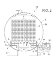
FIG. 2 is a transverse cross-sectional view taken at the location of line A-A ofFIG. 1 ; -
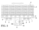
FIG. 3 is a partial cross-sectional view taken at the location of line B-B ofFIG. 1 ; -
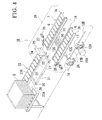
FIG. 4 is a perspective view showing another embodiment of a retort sterilizing apparatus used to carry out the retort sterilizing method of the present invention; -
FIG. 5 is an overhead view showing the general structure of a retort sterilizing apparatus used to carry out another retort sterilizing method of the present invention; -
FIG. 6 is a transverse cross-sectional view taken at the location of line C-C ofFIG. 5 ; -
FIG. 7 is a graph showing measurement results in the case of carrying out a sterilization processing test while sliding retorted products at 30 Hz according to the retort sterilizing method of the present invention; -
FIG. 8 is a graph showing measurement results in the case of carrying out a sterilization processing test while sliding retorted products at 35 Hz according to the retort sterilizing method of the present invention; -
FIG. 9 is a graph showing measurement results in the case of carrying out a sterilization processing test while sliding retorted products at 40 Hz according to the retort sterilizing method of the present invention; -
FIG. 10 is a graph showing measurement results in the case of carrying out a sterilization processing test while sliding retorted products at 45 Hz according to the retort sterilizing method of the present invention; -
FIG. 11 is a graph showing an example of the case of changing the sliding frequency of carriages during a retorting operation according to the retort sterilizing method of the present invention; and -
FIG. 12 is a longitudinal cross-sectional view of a retort sterilizing apparatus proposed in the prior art. -
- 1A, 1B, 1C
- Sterilizing apparatus
- 2
- Support leg
- 3
- Retort
- 3A
- Retort body
- 3B,3C
- Cover
- 4
- Retorted product
- 5
- Tray
- 6
- Tray holding roller
- 7
- Carriage
- 7A
- Roller support frame
- 9,30
- Carriage holding roller
- 10
- Cam follower
- 10A
- Cam guide surface
- 11
- Eccentric cam
- 12,12A,12B,12C
- Rotating driveshaft
- 13
- Shaft sealing mechanism
- 14
- Shaft joint
- 15
- Mounting bracket
- 16,16A
- Motor (rotating drive source)
- 17,18
- Gear box
- 19
- Guide rail
- 20
- Traveling guide wheel
- 21
- Relay carriage
- 22
- Dog
- 23
- Roller conveyor
- 23A
- Transfer roller
- 24
- Relay roller
- 25
- Relay frame
- 26
- Actuator
- 27
- Stopper
- 30
- Sealing mechanism
- 36
- Coupling rod
- 37
- Support arm
- 38
- Drive source
- 38A
- Drive rod
- The following provides an explanation of an embodiment of the present invention based on the drawings.
As shown inFIGS. 1 to 3 , a sterilizing apparatus 1A of the present embodiment has aretort 3 held withsupport legs 2 on a floor surface.
Theretort 3 is constituted by acylindrical retort body 3A and covers 3B and 3C attached to the ends on the front and back in the lengthwise direction thereof. In the present embodiment, a sterilizingapparatus 1 is arranged an intermediate point of a transfer line in a factory not shown with the lengthwise direction of theretort 3 facing in the direction of transfer of the transfer line. - In addition, although not shown in detail, the front and back covers 3B and 3C are each able to be opened and closed, and retorted products not yet sterilized that have been transferred from a previous line with the transfer line are able to be loaded into the
retort body 3A by opening theback cover 3B (cover on the upstream side of the direction of transfer, or in other words, the loading side).
In addition, retorted products on which sterilization processing with the sterilizingapparatus 1 has been completed can be unloaded to the downstream side of the transfer line and transferred to the next step by the transfer line by opening thefront cover 3C (cover on the downstream side in the direction of transfer, or in other words the unloading side). - Thus, loading of unprocessed retorted products into the
retort body 3A of the sterilizingapparatus 1 and unloading of processed retorted products from theretort body 3A can be carried out simultaneously by opening thecover 3B and thecover 3C, and when loading of all unprocessed retorted products into theretort body 3A has been completed, thecovers apparatus 1. In addition, in order to prevent contamination by unsterilized products, an interlock control can be provided that only starts loading of unprocessed products aftercover 3B has been closed following transfer of sterilized trays. - As shown in
FIG. 2 , a large number of retortedproducts 4, which have been loaded into theretort body 3A by a conveyor of the transfer line, are respectively housed in rows ontrays 5 stacked in a plurality of layers, and thesestacked trays 5 are removably coupled and fixed by a fixing tool not shown so that the stacks thereof do not collapse. Furthermore, thesetrays 5 are omitted fromFIG. 1 . - These retorted
products 4 have contents sealed in a packaging bag comprising lamination of a heat-resistant synthetic resin and aluminum foil, are inserted one at a time between a large number of dividers provided on thetrays 5, and are arranged in rows so as not to shift out of position or fall outside thetrays 5 even during vibration of thetrays 5. - The lower surfaces in the vicinity of the side edges on both the left and right sides of the
lowermost trays 5 stacked in a plurality of layers within theretort body 3A are supported by a plurality oftray holding rollers 6 provided in two rows to the left and right in the lower portion of theretort body 3A. Both ends of thesetray holding rollers 6 are rotatably supported with bearings by roller support frames 7A comprising a portion ofcarriages 7 provided in the lower portion of theretort body 3A, and thetrays 5 stacked in a plurality of layers are able to move within theretort body 3A in the lengthwise direction thereof by the rotation of thesetray holding rollers 6. - In addition, as shown in
FIG. 3 , the length of each of these roller support frames 7A is set to be roughly equal to the length of one side of thetrays 5 along the lengthwise direction of theretort body 3A, and groups of thetrays 5 stacked in a plurality of layers are placed so as to span pairs of roller support frames 7A on the left and right sides. Furthermore, although not shown in the drawing, stopper mechanisms are provided in the vicinity of the ends of each of the roller support frames 7A on the left and right sides in opposition to the lengthwise direction thereof in order to restrict the movement of the groups oftrays 5 placed on thetray holding rollers 6, enabling groups oftrays 5 to be fixed in position on the left and right pairs of roller support frames 7Aduring sterilizationprocessing and the like of the retortedproducts 4. - As shown in
FIGS. 2 and3 , the lower surfaces of the roller support frames 7A comprising thecarriages 7 are supported on a plurality of rows ofcarriage holding rollers 9 fixed to the inside and bottom of theretort body 3 and respectively and rotatably supported with bearings by pairs of roller support frames 8 on the left and right sides, and thecarriages 7 are able to move freely within a prescribed range in the lengthwise direction of the retort body 3Aby allowing thesecarriage holding rollers 8 to rotate freely. - In addition, as shown in
FIG. 2 , pairs of left andright cam followers 10 are attached to thecarriages 7. Pairs of cam guide surfaces 10A respectively arranged in a row to the front and back in the perpendicular direction as shown inFIG. 3 are formed in thesecam followers 10, andeccentric cams 11 are respectively arranged between these cam guide surfaces 10A. Theseeccentric cams 11 are fixed to arotating driveshaft 12 rotatably supported with bearings in the lower portion of theretort body 3A in an orientation that transverses to the left and right the lengthwise direction of theretort body 3A. The rotatingdriveshaft 12 protrudes outside theretort body 3A by passing through the inside of a shaft sealing mechanism 13, and is coupled by a shaft joint 14 to an output shaft of a rotating drive source in the form of amotor 16 fixed on a mountingbracket 15 provided on the side of thesupport leg 2. - The shaft sealing mechanism 13 employs a structure in which the periphery of the
rotating driveshaft 12 is rotatably sealed with a gasket sealing member so that high-temperature and high-pressure steam within theretort body 3A does not escape to the outside during sterilization processing. Furthermore, in the present embodiment, a cam mechanism of the present invention is composed by thecam followers 10 and theeccentric cams 11. - Next, an explanation is provided of the operation of the sterilizing
apparatus 1 configured in the manner described above.
Unsterilized retortedproducts 4 are housed in thetrays 5 stacked in a plurality of layer and carried to just in front of theretort 3 by a conveyor of a transfer line not shown where they are temporarily stopped and paused. At this time, thecover 3B of theretort 3 is opened, and a group of thetrays 5 stacked in a plurality of layers is transferred onto thetray holding rollers 6 within theretort body 3A from the conveyor of the transfer line. In the present embodiment, although forward movement of thetrays 5 stacked in a plurality of layers on thetray holding rollers 6 within theretort body 3A is carried out by being pushed from the outside by allowing thetray holding rollers 6 to rotate freely, each of thetray holding rollers 6 may be synchronously driven collectively for each group of left and right pairs of the roller support frames 7A by a drive source such as a motor not shown. - Furthermore, a means for moving the
trays 5 stacked in a plurality of layers within theretort body 3A is not limited to thetray holding rollers 6 driven by a motor and the like, but rather a pushing mechanism can be used that is arranged between the rows oftray holding rollers 6 on both the left and right sides and uses pusher dogs driven with cylinder apparatuses and the like, and the pusher dogs may be made to engage with thelowermost trays 5 so as to push thetrays 5 stacked in a plurality of layers forward at a prescribed stroke interval. - Thus, at the point each group of
trays 5 stacked in a plurality of layers is pushed in order starting with the first group to the end of each of the roller support frames 7A arranged in series symmetrically on the left and right sides, eachlowermost tray 5 is held in position so as not to move forward or backward (lengthwise direction of the retort 3) by a stopper mechanism not shown as a result of being detected by a detection means not shown. - Thus, after all groups of the
trays 5 on which are placed retortedproducts 4 to undergo sterilization processing are loaded into theretort body 3A, theback cover 3B is closed and heat sterilization processing of the retortedproducts 4 begins within theretort 3. In addition, simultaneous to the start of sterilization processing, themotor 16 provided outside theretort 3 is driven. - When the
motor 16 is driven, the rotatingdriveshaft 12 rotates and the eccentric cam 11s are driven and rotated. As a result, thecam followers 10, having the pair of cam guide surfaces 10A opposing both sides of the outer periphery of theeccentric cams 11, move reciprocally in the forward and backward directions (lengthwise direction) of theretort body 3A accompanying rotation of theeccentric cams 11. Accompanying the reciprocal motion of thecam followers 10, thecarriages 7 fixed thereto also slide in the forward and backward directions of theretort body 3A. - Since the movement of the groups of
trays 5 stacked in a plurality of layers placed on thecarriages 7 is restricted on thecarriages 7 by the stopper mechanism described above, the groups oftrays 5 also slide together with thecarriages 7. Accompanying the sliding motion of thetrays 5, the contents of the retortedproducts 4 housed therein slide within the packaging bags, and as a result thereof, the contents are subjected to agitation effects and temperature unevenness within the packaging bags is reduced, thereby allowing the contents to be sterilized in a short period of time while also making it possible to avoid partially incomplete sterilization and scorching caused by overheating. - Driving of the
motor 16 continues even after completion of heat sterilization processing inside theretort 3 to slide the groups oftrays 5 while carrying out cooling processing of the retortedproducts 4. As a result of cooling while sliding the groups oftrays 5 in this manner, the time required for cooling can be shortened. Once cooling processing has been completed, covers 3B and 3C provided at the front and back ends of theretort body 3A are opened, and each group of thetrays 5 housing the processed retortedproducts 4 in theretort body 3A are sent out from thefront cover 3C onto a conveyor of a transfer line not shown starting with the first group of thetrays 5 and transferred to the next step. - At the same time, groups of trays (not shown) housing unprocessed retorted
products 4, which have been transferred from the previous step and which are stacked in a plurality of layers and waiting on a conveyor of a transfer line, are sequentially loaded from the side of theback cover 3B into theretort body 3A, and once all of these groups of trays have been loaded into theretort body 3A, the front and back covers 3B and 3C are closed and the previously described processed is repeated. - Furthermore, in the present embodiment, since the front and back covers 3B and 3C of the
retort body 3A are opened simultaneously, enabling processed groups of thetrays 5 to be unloaded from inside theretort body 3A while groups of unprocessed trays are simultaneously loaded therein, the cycle time of the sterilization processing step can be shortened. - Next,
FIG. 4 is a perspective view showing another embodiment of the retorted product sterilizing apparatus as claimed in the present invention. An outline of the contour of theretort body 3A in asterilizing apparatus 1B is indicated with a virtual line inFIG. 4 .
In the sterilizingapparatus 1B, arotating driveshaft 12A of amotor 16A provided outside theretort body 3A is drivingly coupled to arotating driveshaft 12B extending in the lengthwise direction of theretort body 3A through agear box 17 provided on the upper end of asupport leg 2A that supports theretort body 3A, and is further drivingly coupled to arotating driveshaft 12C, the orientation of the rotation axis line thereof being perpendicular to therotating driveshaft 12B, through agear box 18 provided on the upper end of anadjacent support leg 2A. - Thus, when the
rotating driveshaft 12A of themotor 16A rotates, the rotation thereof is transmitted to therotating driveshaft 12B and further transmitted to therotating driveshaft 12C. Theeccentric cams 11 are fixed to therotating driveshaft 12C, and thecam followers 10 are moved reciprocally by the rotation of theeccentric cams 11 as the roller support frames 7A slide. - Furthermore, although not shown in the drawings, the
gear box 18 is provided at a plurality of locations along the forward and backward directions (lengthwise direction) of theretort body 3A, and therotating driveshaft 12C to which theeccentric cam 11 is provided at a plurality of locations corresponding to each of thegear boxes 18. - In addition, the left and right pairs of roller support frames 7A on which the
tray holding rollers 6 are arranged are provided in a plurality of groups of rows in the lengthwise direction of theretort body 3A in the same manner as shown inFIG. 1 although not shown inFIG. 4 , and each group of the left and right pairs of roller support frames 7A is collectively slid in the forward and backward directions of theretort body 3A by theeccentric cams 11 fixed on therotating driveshafts 12C provided corresponding thereto. - In the sterilizing
apparatus 1B of the present embodiment, free-rolling rollers not having a drive source are used for thetray holding rollers 6, and arelay carriage 21, guided by travelingguide wheels 20 on a pair of left and right guide rails 19 provided on the bottom inside theretort body 3A between the left and right roller support frames 7A, is used for loading and unloading thetrays 5 stacked in a plurality of layers. Therelay carriage 21 is provided with a pair ofdogs 22 that removably retain the front and back ends of thelowermost tray 5 stacked in a plurality of layers by clamping from the forward and backward directions in the vicinity of both ends in the forward and backward directions of the upper surface thereof, and is able to move reciprocally between the inside of theretort body 3A androller conveyors 23 installed outside theretort body 3A. - The
trays 5 stacked in a plurality of layers are housed inside theretort body 3A by being supported in order by left andright transfer rollers 23A provided on theroller conveyors 23,relay rollers 24 and thetray holding rollers 6, and by being pushed by therelay carriage 21. Furthermore, the pair ofdogs 22 are comprised to be erected and collapsed by a drive means not shown installed on therelay carriage 21. - The groups of
trays 5 housed in theretort body 3A are held in position at a prescribed location with their forward and backward movement relative to the roller support frames 7A being restricted bystoppers 27 driven to advance and retract from both sides above thetray holding rollers 6 byactuators 26 attached at the front and back thereof on the side of the roller support frames 7A. - Although only partially shown in the drawing, the
stoppers 27 and theactuators 26, which cause them to advance and retract, are respectively provided on the front and back ends of the pair of left and right roller support frames 7A. In addition, although not shown in detail in the drawing, when therelay carriage 21 is on the side of theroller conveyors 23, the travel thereof is guided by a pair of guide rails having the same structure as the guide rails 19 respectively provided on the insides of the rows of the left andright transfer rollers 23A, and when leaving and entering theretort body 3A, are guided by guides having the same cross-sectional shape as the guide rails 19 respectively formed on a pair of left and right relay frames 25, thereby enabling therelay carriage 21 to transfer to the side of the guide rails 19.
Furthermore, an endless or fluid cylinder apparatus such as a chain or timing belt is used to drive the reciprocating travel of therelay carriage 21, and can be carried out by a drive means equipped with a drive source on the side of therelay carriage 21. - Furthermore, in the present embodiment, since the load to each
motor 16A can be dispersed if thegear box 17 driven and coupled to themotor 16A is arranged at a plurality of locations and a commonrotating driveshaft 12B is driven by a plurality of themotors 16A, a small motor can be used for the rotating drive source. Moreover, by using carriages having independent groups of roller support frames 7A in which respective groups of left and right pairs slide as a single unit, arranging a plurality of these carriages in series in theretort body 3A, supporting each of the carriages individually while allowing to slide, and causing each carriage to slide in a mutually different phase by varying the phase of the angle of rotation of theeccentric cam 11 that drives each carriage, resonance of the overall sterilizing apparatus can be suppressed, thereby making it possible to reduce the effects of vibrations and noise on the area around the sterilizing apparatus. - In addition, although an eccentric cam mechanism is used as a cam mechanism to slide carriages in the forward and backward directions of a retort in the embodiments explained above, a structure can also be employed in which a cylindrical cammechanism, for example, is used as a cam mechanism, cam followers are guided in cam grooves formed in the peripheral surfaces of cylindrical cams and the cam followers can be allowed to move reciprocally in the axial direction of the cylindrical cams, and sterilization processing can be carried out while allowing retorted products to slide in the leftward and rightward directions relative to the retort body by supporting the carriages to as to be able to move in the leftward and rightward directions of the retort body.
-
FIGS. 6 and7 show a sterilizing apparatus for retorted products as claimed in another embodiment of the present invention. In the apparatus of this embodiment, drive sources for sliding carriages reciprocally are linear reciprocating drive sources provided independently for each carriage and provided perpendicular to the lengthwise direction of the retort, and the carriages are independently slid in a horizontal direction perpendicular to the lengthwise direction by the linear reciprocating drive sources. The following provides an explanation of those aspects of the present embodiment that differ from those of the previously described embodiments while using the same reference symbols for those portions that are the same for both. - In a
sterilizing apparatus 1C for retortedproducts of the present embodiment, eightcarriers 7 within theretort 3 are supported oncarriage holding rollers 8 provided in two rows each in the horizontal direction perpendicular to the lengthwise direction of theretort body 3A. Thesecarriage holding rollers 30 are rotatably supported on both ends with bearings byroller holding frames 31 attached to both the left and right sides at the lower portion of the inner periphery of theretort body 3A, and each of thecarriages 7 is able to move freely in the horizontal direction perpendicular to the lengthwise direction of theretort body 3A within theretort body 3A by allowing thesecarriage holding rollers 30 to rotate freely. - In addition, one end of a
coupling rod 36, which passes through the peripheral wall of theretort body 3A, is coupled to eachcarriage 7 through asealing mechanism 35 that isolates the inside and outside of theretort 3 as shown inFIG. 6 . The other end of thecoupling rod 36 is coupled to adrive rod 38A provided in a drive source in the form of anair cylinder mechanism 38 attached to asupport arm 37 provided protruding from the outer peripheral surface of theretort 3. - As shown in
FIG. 5 , theair cylinder mechanism 38 is provided in a quantity equal to the number ofcarriages 7, and in the present embodiment, a total of eight of theair cylinder mechanisms 38 are provided, and each is driven and controlled by a drive control mechanism not shown. - When the driving
rods 38A of theair cylinder mechanisms 38 are repeatedly driven to advance and retract at a prescribed cycle and stroke in the horizontal direction perpendicular to the lengthwise direction of theretort 3, the movement of the drivingrods 38A is transmitted to thecarriages 7 through thecoupling rods 36, and thecarriages 7 are configured so as to slide in the same direction as the drivingrods 38A while being supported by thecarriage holding rollers 30. - Here, two groups of
carriages 7, respectively supporting the lower surfaces of thelowermost tray 5 of each group oftrays 5 stacked in a plurality of layers at both the left and right sides, are driven and controlled in coordination with theair cylinder mechanisms 38 that drive eachcarriage 7 so that thecarriages 7 move at mutually the same amplitude, in the same phase and in synchronization. - Furthermore, two of these
carriages 7 may be configured in the form of an integral member by coupling together, and in this case, theseintegral carriages 7 may be driven using a drive source such as a single air cylinder mechanism. In addition, the drive source for sliding the carriages is not limited to the air cylinder mechanism, but rather a rotating drive source in the manner of a motor, for example, may be used so as to slide the carriages by means of a cranking mechanism. - Although not shown in the drawings, the sterilizing
apparatus 1 of the present embodiment may be equipped with drive control apparatuses that allow the cycle and phase of reciprocal motion of the drive rods to be individually set for each of four groups consisting of left and right pairs each of the eightair cylinder mechanisms 38 provided on both sides outside theretort 3. - Next, an explanation is provided of the operation of the sterilizing
apparatus 1C configured in the manner described above while focusing on those portions that differ from the previously described embodiments based on the drawings.
After thetrays 5 stacked in a plurality of layers in the retort body are positioned by a stopper mechanism not shown and thecover 3B is closed, sterilization processing of the retorted products by heating begins within theretort 3. In addition, together with the start of sterilization processing, each of theair cylinder mechanisms 38 provided outside theretort 3 is collectively driven and eachcarriage 7 begins to slide in the leftward and rightward directions. As a result, each group P1, P2, P3 and P4 of thetrays 5 stacked in a plurality of layers slides reciprocally at a right angle to the lengthwise direction of the retort body. - Accompanying the sliding motion of the
trays 5, the contents of the retortedproducts 4 housed therein slide within the packaging bags. As a result, the temperature of the contents is uniform throughout the entire inside of the packaging bags due to agitation effects, thereby avoiding partially incomplete sterilization and scorching caused by over heating. Inaddition, theagitationeffects on the contents also enable the sterilization time to be shortened. - Furthermore, in the present embodiment, since the sliding cycles and sliding phases of the groups P1, P2, P3 and P4 of the
trays 5 can be changed individually, varying these sliding cycles and sliding phases enables resonance of theoverall sterilizing apparatus 1C to be suppressed, thereby making it possible to reduce the effects of vibrations and noise on the area around the sterilizingapparatus 1C. - Following completion of sterilization processing, the retorted
products 4 continue to undergo cooling processing while sliding the groups P1, P2, P3 and P4 of thetrays 5 for a short time thereafter. Cooling the groups P1, P2, P3 and P4 of thetrays 5 while sliding in this manner makes it possible to shorten the amount of time required for cooling. - Sterilization processing tests were carried out by sliding retorted products at various frequencies in order to confirm the effects of a retort sterilizing method using an apparatus of the present invention. Those results are shown in
FIGS. 7 to 10. FIGS. 7 to 10 are graphs showing measurement results when sterilization processing tests were carried out by sliding retorted products at various frequencies, the retorted products used for measurement consisted of 1 kg packages of curry soup, the sterilization temperature within the retort was 120°C, come-up time was 12 minutes, sterilization advances to the next step at a sterilization value in the form of an Fo value of 5, and the sliding stroke of the retorted products was 75 mm. - Here, "come-up time" refers to the amount of time until the ambient temperature inside the retort reaches the sterilization temperature, and a come-up time of 12 minutes means that the amount of time from the start of sterilization to the time the ambient temperature inside the retort reaches 120°C is 12 minutes. In addition, "advancing to the next step" refers to advancing from the retorted product sterilization step to the cooling step, and here, advancing to the next step at an Fo value of 5 means that the sterilization step advances to the cooling step when the Fo value of the retorted products has reached 5.
- The graph of
FIG. 7 shows the results of carrying out sterilization processing while sliding the retorted products at a sliding frequency of 30 Hz, and in this example, the amount of time from the start of sterilization until the Fo value reaches 5 was 31minutes 10 seconds, the amount of time from the start of sterilization until the product temperature has decreased to 50°C after entering the cooling step following heating was 50minutes 12 seconds, and the final Fo value was 8.19. - In addition, the graph of
FIG. 8 shows the results of carrying out sterilization processing while sliding the retorted products at a sliding frequency of 35 Hz, and in this example, the amount of time from the start of sterilization until the Fo value reaches 5 was 28 minutes 01 second, the amount of time from the start of sterilization until the product temperature has decreased to 50°C after entering the cooling step following heating was 45 minutes 46 seconds, and the final Fo value was 7.77. - In addition, the graph of
FIG. 9 shows the results of carrying out sterilization processing while sliding the retorted products at a sliding frequency of 40 Hz, and in this example, the amount of time from the start of sterilization until the Fo value reaches 5 was 23 minutes 52 seconds, the amount of time from the start of sterilization until the product temperature has decreased to 50°C after entering the cooling step following heating was 36minutes 20 seconds, and the final Fo value was 6.82. - In addition, the graph of
FIG. 10 shows the results of carrying out sterilization processing while sliding the retorted products at a sliding frequency of 45 Hz, and in this example, the amount of time from the start of sterilization until the Fo value reaches 5 was 22 minutes 42 seconds, the amount of time from the start of sterilization until the product temperature has decreased to 50°C after entering the cooling step following heating was 34minutes 17 seconds, and the final Fo value was 6.75. - In addition, although not shown in the drawings, in the case of carrying out sterilization processing with the retorted products in a stationary state without sliding the carriages to serve as a comparative example, the amount of time from the start of sterilization until the Fo value reaches 5 was 110 minutes, the amount of time from the start of sterilization until the product temperature has decreased to 50°C after entering the cooling step following heating was 2
hours 45 minutes, and the final Fo value was 7. In addition, in the case, observation of the status of the retorted products following sterilization revealed the presence of portions in which the contents were partially scorched, or in other words, portions in which so-called "retort browning" occurred. On the basis of these results, according to the sterilizing method of the present invention, sterilization time was confirmed to be able to be shortened considerably as compared with conventional methods, and the contents of retorted products were confirmed to be able to be uniformly sterilized without the occurrence of scorched portions or portions that escaped sterilization. - Although the carriages were slid at the same frequency from the start to completion of processing in the above embodiments, the motor serving as a rotating drive source during retort operation can be switched on and off and the speed thereof can be controlled as desired, and the sliding frequency of the carriages during retort processing can be controlled as desired by switching on and off and freely controlling the speed of motor. In the case the contents to be sterilized are susceptible to separation of an oil fraction or susceptible to foaming, there are cases in which it is desirable to not slide the contents as much as possible. In such cases, sterilization can be carried out efficiently and uniformly without having an effect on the contents by holding sliding to the absolute minimum.
-
FIG. 11 shows an example of the case of changing the sliding pattern by controlling the sliding frequency of the carriages during retort operation to the optimum frequency according to the ambient temperature. In this example, the pattern used for sterilization processing consists of not sliding the carriages until the ambient temperature following the start of processing reaches 80°C (namely, sliding frequency of 0 Hz with the motor switched off), sliding the carriages at 30 Hz until the sterilization temperature rises from 80°C to the sterilization temperature of 120°C, sliding at 45 Hz during sterilization, lowering the sliding frequency to 35 Hz following completion of sterilization until the temperature falls to 80°C in the cooling step, and then discontinuing sliding when the ambient temperature has fallen to 80°C. Since product temperature can be controlled by arbitrarily changing the sliding pattern during processing in this manner, retort processing can be carried out under the optimum conditions at all times without causing excessive sliding simply by presetting the pattern in accordance with the type of product to be sterilized by determining the optimum sliding pattern in advance for each type or size of product to be sterilized and then storing that pattern in a controller in the form of a program. In addition, there is also the advantage of extending the service life of the retort apparatus itself by holding sliding of the carriages to the absolute minimum in this manner. Although changing the sliding pattern was carried out according to ambient temperature in the example above, the sliding frequency can also be changed according to product temperature by monitoring product temperatures of products to be sterilized, for example. - The sterilizing method and sterilizing apparatus for retorted products of the present invention can be used to sterilize retorted products having foods or pharmaceuticals and the like sealed inside, and are particularly preferable for retorted products in which solid products or highly viscous contents are sealed in a packaging bag and the like and which use a large or thick packaging bag.
Claims (11)
- A sterilizing method for retorted products, in which carriages on which retorted products are placed are slid within a retort while carrying out heat sterilization processing on the retorted products, wherein driving force of a drive source installed outside the retort is transmitted to the carriages after being converted to reciprocal motion, and the carriages are slid reciprocally at a preset prescribed cycle in forward and backward or leftward and rightward directions of the retort.
- The sterilizing method for retorted products according to claim 1, wherein the drive source is a rotating drive source using a motor installed outside the retort, rotary motion of the rotating drive source is transmitted to the carriages after being converted to reciprocal motion by a cam mechanism, and the carriages are slid in the forward and backward or leftward and rightward directions of the retort.
- The sterilizing method for retorted products according to claim 1, wherein the drive source is a linear reciprocating drive source provided independently for each of the carriages and provided in a direction perpendicular to a lengthwise direction of the retort, and the carriages are slid independently in a horizontal direction perpendicular to the lengthwise direction by the linear reciprocating drive source.
- The sterilizing method for retorted products according to any of claims 1 to 3, wherein at least one of either a cycle or phase of the sliding of the carriages is varied between the carriages arranged in a row in the lengthwise direction in the retort.
- The sterilizing method for retorted products according to any of claims 1 to 3, wherein a slidingpattern can be changed in accordance with products to be sterilized by controlling a sliding frequency of the carriages during retort processing.
- A sterilizing apparatus for retorted products, in which carriages on which retorted products are placed are slid within a retort while carrying out heat sterilization processing on the retorted products, the sterilizing apparatus for retorted products comprising: a plurality of carriages which are arranged in a row in a lengthwise direction in the retort, are provided so as to be able to respectively slide reciprocally in the lengthwise direction or a horizontal direction perpendicular to the lengthwise direction, and hold trays housing retorted products; and a reciprocating drive source that allows the carriages to slide reciprocally within the retort, wherein the reciprocating drive source is installed outside the retort.
- The sterilizing apparatus for retorted products according to claim 6, wherein the reciprocating drive source is a rotating drive source using a motor installed outside the retort, a rotating drive shaft driven by the rotating drive source rotatably passes through a retort wall by means of a shaft sealing mechanism, the rotating drive shaft is driven by a cam mechanism within the retort by being coupled thereto, rotary motion of the rotating drive shaft is transmitted to the carriages after being converted to reciprocal motion by the cam mechanism, and the carriages are slid in forward and backward or leftward and rightward directions of the retort.
- The sterilizing apparatus for retorted products according to claim 6, wherein the reciprocating drive source is a linear reciprocating drive source provided independently for each of the carriages and using a plurality of cylinder apparatuses provided in a direction perpendicular to the lengthwise direction of the retort.
- The sterilizing apparatus for retorted products according to any of claims 6 to 8, wherein the reciprocating drive source drives the carriages by varying at least one of either a cycle or phase of the sliding between the carriages arranged in a row in the lengthwise direction in the retort.
- The sterilizing apparatus for retorted products according to claim 7, wherein the cam mechanism is constituted by eccentric cams rotated and driven by the rotating drive source, and cam followers attached to the carriages.
- The sterilizing apparatus for retorted products according to any of claims 6 to 8, wherein speed of the reciprocating drive source is variable, and a sliding pattern can be changed in accordance with products to be sterilized by controlling a sliding frequency of the carriages during retort processing.
Applications Claiming Priority (3)
| Application Number | Priority Date | Filing Date | Title |
|---|---|---|---|
| JP2006190138A JP4941642B2 (en) | 2006-07-11 | 2006-07-11 | Method and apparatus for sterilizing retort products |
| JP2007150376A JP5321773B2 (en) | 2007-06-06 | 2007-06-06 | Method and apparatus for sterilizing retort products |
| PCT/JP2007/063717 WO2008007659A1 (en) | 2006-07-11 | 2007-07-10 | Sterilizing method and sterilizing apparatus for retorted product |
Publications (3)
| Publication Number | Publication Date |
|---|---|
| EP2042044A1 true EP2042044A1 (en) | 2009-04-01 |
| EP2042044A4 EP2042044A4 (en) | 2010-05-05 |
| EP2042044B1 EP2042044B1 (en) | 2012-03-21 |
Family
ID=38923218
Family Applications (1)
| Application Number | Title | Priority Date | Filing Date |
|---|---|---|---|
| EP07790535A Ceased EP2042044B1 (en) | 2006-07-11 | 2007-07-10 | Sterilizing method and sterilizing apparatus for retorted product |
Country Status (5)
| Country | Link |
|---|---|
| US (1) | US8262987B2 (en) |
| EP (1) | EP2042044B1 (en) |
| KR (1) | KR101405077B1 (en) |
| AU (1) | AU2007273589B2 (en) |
| WO (1) | WO2008007659A1 (en) |
Cited By (3)
| Publication number | Priority date | Publication date | Assignee | Title |
|---|---|---|---|---|
| GB2448147B (en) * | 2007-04-03 | 2010-02-24 | Zinetec Ltd | Food processing |
| FR2951090A1 (en) * | 2009-10-13 | 2011-04-15 | Steriflow | System for agitating article e.g. liquid products including dairy products present in autoclave under pressure, comprises enclosure with heating and pressurizing units, and storage rack translationally coupled with agitating unit |
| EP2311327A1 (en) * | 2009-10-13 | 2011-04-20 | Steriflow | System for shaking items inside a pressurised device, in particular an autoclave |
Families Citing this family (24)
| Publication number | Priority date | Publication date | Assignee | Title |
|---|---|---|---|---|
| US12515838B2 (en) | 2020-10-01 | 2026-01-06 | Stock America Llc | Retort system and process |
| JP2010057463A (en) * | 2008-09-08 | 2010-03-18 | Toyo Seikan Kaisha Ltd | Sterilization method of fluid food packed in pouch |
| JP5434924B2 (en) * | 2008-10-03 | 2014-03-05 | 東洋製罐株式会社 | Disinfection method for pouch-packed fluid food |
| KR101108667B1 (en) * | 2009-06-16 | 2012-01-25 | 주식회사 협진기계 | Retort Food Sterilizer |
| CN102008738A (en) * | 2010-11-01 | 2011-04-13 | 张家港市环宇制药设备有限公司 | Soft bag sterilization vehicle tray |
| WO2013022815A1 (en) * | 2011-08-10 | 2013-02-14 | Allpax Products Llc | Retort with progressive latch, roller support arrangement and method and system for reciprocation of loads |
| US8808638B2 (en) | 2011-09-16 | 2014-08-19 | Tomoda Selling & Sailing Co., Ltd. | Retort sterilization device, heating device, heat sterilization method, and heat treatment method |
| AU2013255434A1 (en) * | 2012-05-02 | 2014-11-06 | Nestec S.A. | Methods for mixing products using acoustic mixing |
| US9668509B2 (en) | 2014-03-16 | 2017-06-06 | John Bean Technologies Corporation | Retort agitation system |
| DE102014004785B4 (en) * | 2014-04-02 | 2023-02-02 | Fresenius Medical Care Deutschland Gmbh | Process for sterilizing a measuring probe |
| KR20160056167A (en) * | 2014-11-11 | 2016-05-19 | 삼성전자주식회사 | Method of manufacturing a light emitting device, apparatus for inspection of a light emitting module, and method of making a decision on whether a light emitting module meets a quality requirement |
| US20190159486A1 (en) | 2017-11-29 | 2019-05-30 | IXON Food Technology Limited | Method for Preparing Food |
| KR102151772B1 (en) * | 2018-11-07 | 2020-10-27 | 주식회사 경한 | Shaking device of retort sterilized food for steam sterilizer |
| US11533935B2 (en) * | 2019-07-01 | 2022-12-27 | John Bean Technologies Corporation | Retort agitation system and method |
| KR102455201B1 (en) * | 2020-03-02 | 2022-10-18 | 씨제이제일제당 (주) | Sterilizing module |
| KR102481536B1 (en) * | 2020-03-02 | 2022-12-26 | 씨제이제일제당 (주) | Sterilizer |
| JP7737128B2 (en) * | 2021-03-26 | 2025-09-10 | 国立研究開発法人農業・食品産業技術総合研究機構 | Method for producing a paste-like composition |
| KR102404173B1 (en) * | 2021-08-19 | 2022-06-02 | 씨제이제일제당 (주) | Packing and cart treatment system including same |
| CN113648435B (en) * | 2021-09-02 | 2023-02-17 | 江苏天宇伟业智能装备股份有限公司 | Multifunctional horizontal sterilizing kettle |
| CN114404637B (en) * | 2021-12-20 | 2025-11-21 | 华润双鹤药业股份有限公司 | Frame reciprocating rectilinear motion type sterilizing cabinet |
| KR102863489B1 (en) * | 2022-12-30 | 2025-09-24 | 김내욱 | Retort sterilizer |
| KR102707283B1 (en) | 2024-05-28 | 2024-09-19 | 주식회사 엠씨맥스 | Sterilization device with a sequential movement structure of containers loaded with retort pouches |
| KR102707284B1 (en) | 2024-05-28 | 2024-09-19 | 주식회사 엠씨맥스 | Sterilization system for retort pouches using AGV |
| CN119817646B (en) * | 2025-01-27 | 2025-09-26 | 广州王老吉大健康产业有限公司 | A rapid sterilization method and sterilization device for beverage processing |
Citations (2)
| Publication number | Priority date | Publication date | Assignee | Title |
|---|---|---|---|---|
| JP2006190138A (en) | 2005-01-07 | 2006-07-20 | Mitsubishi Electric Corp | Alarm management device, alarm management method and program |
| JP2007150376A (en) | 2007-03-20 | 2007-06-14 | Sharp Corp | Nitride semiconductor light-emitting device, epi-wafer and method of manufacturing the same |
Family Cites Families (11)
| Publication number | Priority date | Publication date | Assignee | Title |
|---|---|---|---|---|
| US2134817A (en) * | 1934-09-26 | 1938-11-01 | Gerber Prod | Reciprocating cooker |
| US3446636A (en) * | 1966-04-20 | 1969-05-27 | Big Stone Canning Co | Method for heat sterilizing food in sealed containers |
| US4170421A (en) * | 1978-09-05 | 1979-10-09 | American Hospital Supply Corporation | Reciprocal sterilizing agitator system (RSAS) |
| JPS582666B2 (en) | 1980-06-12 | 1983-01-18 | 東洋製罐株式会社 | Method and device for sterilizing retort food |
| US4748816A (en) * | 1986-11-10 | 1988-06-07 | Reynolds Metals Company | Method for thermally treating filled cans |
| KR0164023B1 (en) * | 1994-08-24 | 1998-12-15 | 오오쯔카 요시미쯔 | Spray-type sterilizer apparatus and sterilizing method |
| GB9420650D0 (en) * | 1994-10-13 | 1994-11-30 | Metal Box Plc | Thermal processing method and apparatus for use with packaging containers |
| JP3977567B2 (en) * | 2000-02-21 | 2007-09-19 | 株式会社日阪製作所 | Swing / rotation type spray retort sterilizer |
| JP3977568B2 (en) * | 2000-02-25 | 2007-09-19 | 株式会社日阪製作所 | Oscillating spray retort sterilizer |
| JP2001245642A (en) | 2000-03-07 | 2001-09-11 | Kamigaki Tekkosho:Kk | Retort sterilizer |
| GB2411335B (en) * | 2004-02-26 | 2007-06-20 | Zinetec Ltd | Heat-treatment apparatus and process |
-
2007
- 2007-07-10 WO PCT/JP2007/063717 patent/WO2008007659A1/en not_active Ceased
- 2007-07-10 US US12/307,977 patent/US8262987B2/en not_active Expired - Fee Related
- 2007-07-10 KR KR1020087030573A patent/KR101405077B1/en not_active Expired - Fee Related
- 2007-07-10 AU AU2007273589A patent/AU2007273589B2/en not_active Ceased
- 2007-07-10 EP EP07790535A patent/EP2042044B1/en not_active Ceased
Patent Citations (2)
| Publication number | Priority date | Publication date | Assignee | Title |
|---|---|---|---|---|
| JP2006190138A (en) | 2005-01-07 | 2006-07-20 | Mitsubishi Electric Corp | Alarm management device, alarm management method and program |
| JP2007150376A (en) | 2007-03-20 | 2007-06-14 | Sharp Corp | Nitride semiconductor light-emitting device, epi-wafer and method of manufacturing the same |
Non-Patent Citations (1)
| Title |
|---|
| See also references of WO2008007659A1 |
Cited By (4)
| Publication number | Priority date | Publication date | Assignee | Title |
|---|---|---|---|---|
| GB2448147B (en) * | 2007-04-03 | 2010-02-24 | Zinetec Ltd | Food processing |
| FR2951090A1 (en) * | 2009-10-13 | 2011-04-15 | Steriflow | System for agitating article e.g. liquid products including dairy products present in autoclave under pressure, comprises enclosure with heating and pressurizing units, and storage rack translationally coupled with agitating unit |
| EP2311327A1 (en) * | 2009-10-13 | 2011-04-20 | Steriflow | System for shaking items inside a pressurised device, in particular an autoclave |
| AU2010227070B2 (en) * | 2009-10-13 | 2016-10-27 | Steriflow | System for shaking items inside a device under pressure, in particular an autoclave |
Also Published As
| Publication number | Publication date |
|---|---|
| EP2042044A4 (en) | 2010-05-05 |
| AU2007273589A1 (en) | 2008-01-17 |
| US20090311131A1 (en) | 2009-12-17 |
| WO2008007659A1 (en) | 2008-01-17 |
| EP2042044B1 (en) | 2012-03-21 |
| KR20090036550A (en) | 2009-04-14 |
| US8262987B2 (en) | 2012-09-11 |
| KR101405077B1 (en) | 2014-06-10 |
| AU2007273589B2 (en) | 2013-01-17 |
Similar Documents
| Publication | Publication Date | Title |
|---|---|---|
| EP2042044B1 (en) | Sterilizing method and sterilizing apparatus for retorted product | |
| CN101489423B (en) | Sterilizing method and sterilizing apparatus for retorted product | |
| JP5321773B2 (en) | Method and apparatus for sterilizing retort products | |
| RU2445243C2 (en) | Device for grouping packages along transfer path | |
| JPH05103585A (en) | Method and device for cold storage process, sterilizing process and germfree packaging for meat product | |
| JP2020507526A (en) | Packaging machine and method for operating packaging machine | |
| JP5972904B2 (en) | Unit for transporting and uprighting sealed packages of injectable food | |
| JP2006168736A (en) | Packaging device that covers and seals the cover film on the tray | |
| JP7839640B2 (en) | A packaging assembly for forming and sealing multiple packs containing an injectable product, and a method for forming and sealing multiple packs. | |
| US12193463B2 (en) | Retort agitation system and method | |
| JP5628740B2 (en) | Bag bottom support device for bag filling and packaging machine | |
| US20070271873A1 (en) | Filling Machine and Method for Packing Comestibles | |
| KR101309032B1 (en) | Structure for conveyer transferring baskets of retort | |
| KR102055577B1 (en) | Compact apparatus for cutting and containing on the spot roasted laver | |
| JP2008308203A (en) | Deaeration packaging method and apparatus for solid food | |
| KR102863489B1 (en) | Retort sterilizer | |
| JP3379629B2 (en) | Heat sterilizer for canned food | |
| CN118770633A (en) | Circulation sealing and cutting device and sealing and cutting method | |
| US3587823A (en) | Transfer mechanism | |
| CN220764923U (en) | Packaging shrink film structure | |
| JP4572701B2 (en) | Container transport device in paper liquid packaging container box filling machine | |
| JP2011103808A (en) | Method for producing aseptic wrapped foods | |
| JP2020520863A (en) | Sealing machine for food containers | |
| CN121158291A (en) | Food packaging machine capable of sterilizing | |
| JPS5844535B2 (en) | Fukuroduzumeshiyokuhinnohansouchi |
Legal Events
| Date | Code | Title | Description |
|---|---|---|---|
| PUAI | Public reference made under article 153(3) epc to a published international application that has entered the european phase |
Free format text: ORIGINAL CODE: 0009012 |
|
| 17P | Request for examination filed |
Effective date: 20090108 |
|
| AK | Designated contracting states |
Kind code of ref document: A1 Designated state(s): AT BE BG CH CY CZ DE DK EE ES FI FR GB GR HU IE IS IT LI LT LU LV MC MT NL PL PT RO SE SI SK TR |
|
| AX | Request for extension of the european patent |
Extension state: AL BA HR MK RS |
|
| DAX | Request for extension of the european patent (deleted) | ||
| RBV | Designated contracting states (corrected) |
Designated state(s): DE FR GB |
|
| TPAC | Observations filed by third parties |
Free format text: ORIGINAL CODE: EPIDOSNTIPA |
|
| A4 | Supplementary search report drawn up and despatched |
Effective date: 20100406 |
|
| RIC1 | Information provided on ipc code assigned before grant |
Ipc: A23L 3/14 20060101ALI20100329BHEP Ipc: A61L 2/04 20060101ALI20100329BHEP Ipc: A23L 3/10 20060101AFI20100329BHEP |
|
| GRAP | Despatch of communication of intention to grant a patent |
Free format text: ORIGINAL CODE: EPIDOSNIGR1 |
|
| GRAS | Grant fee paid |
Free format text: ORIGINAL CODE: EPIDOSNIGR3 |
|
| GRAA | (expected) grant |
Free format text: ORIGINAL CODE: 0009210 |
|
| AK | Designated contracting states |
Kind code of ref document: B1 Designated state(s): DE FR GB |
|
| REG | Reference to a national code |
Ref country code: GB Ref legal event code: FG4D |
|
| REG | Reference to a national code |
Ref country code: DE Ref legal event code: R096 Ref document number: 602007021485 Country of ref document: DE Effective date: 20120516 |
|
| PLBE | No opposition filed within time limit |
Free format text: ORIGINAL CODE: 0009261 |
|
| STAA | Information on the status of an ep patent application or granted ep patent |
Free format text: STATUS: NO OPPOSITION FILED WITHIN TIME LIMIT |
|
| 26N | No opposition filed |
Effective date: 20130102 |
|
| REG | Reference to a national code |
Ref country code: DE Ref legal event code: R097 Ref document number: 602007021485 Country of ref document: DE Effective date: 20130102 |
|
| REG | Reference to a national code |
Ref country code: FR Ref legal event code: PLFP Year of fee payment: 9 |
|
| REG | Reference to a national code |
Ref country code: FR Ref legal event code: PLFP Year of fee payment: 10 |
|
| REG | Reference to a national code |
Ref country code: FR Ref legal event code: PLFP Year of fee payment: 11 |
|
| REG | Reference to a national code |
Ref country code: FR Ref legal event code: PLFP Year of fee payment: 12 |
|
| PGFP | Annual fee paid to national office [announced via postgrant information from national office to epo] |
Ref country code: FR Payment date: 20180725 Year of fee payment: 12 Ref country code: DE Payment date: 20180723 Year of fee payment: 12 |
|
| PGFP | Annual fee paid to national office [announced via postgrant information from national office to epo] |
Ref country code: GB Payment date: 20180719 Year of fee payment: 12 |
|
| REG | Reference to a national code |
Ref country code: DE Ref legal event code: R119 Ref document number: 602007021485 Country of ref document: DE |
|
| GBPC | Gb: european patent ceased through non-payment of renewal fee |
Effective date: 20190710 |
|
| PG25 | Lapsed in a contracting state [announced via postgrant information from national office to epo] |
Ref country code: DE Free format text: LAPSE BECAUSE OF NON-PAYMENT OF DUE FEES Effective date: 20200201 Ref country code: GB Free format text: LAPSE BECAUSE OF NON-PAYMENT OF DUE FEES Effective date: 20190710 |
|
| PG25 | Lapsed in a contracting state [announced via postgrant information from national office to epo] |
Ref country code: FR Free format text: LAPSE BECAUSE OF NON-PAYMENT OF DUE FEES Effective date: 20190731 |