EP2042276A2 - Machine agricole et procédé de détermination de position - Google Patents
Machine agricole et procédé de détermination de position Download PDFInfo
- Publication number
- EP2042276A2 EP2042276A2 EP08162955A EP08162955A EP2042276A2 EP 2042276 A2 EP2042276 A2 EP 2042276A2 EP 08162955 A EP08162955 A EP 08162955A EP 08162955 A EP08162955 A EP 08162955A EP 2042276 A2 EP2042276 A2 EP 2042276A2
- Authority
- EP
- European Patent Office
- Prior art keywords
- attachment
- lifting device
- vehicle
- designed
- agricultural machine
- Prior art date
- Legal status (The legal status is an assumption and is not a legal conclusion. Google has not performed a legal analysis and makes no representation as to the accuracy of the status listed.)
- Granted
Links
- 230000001133 acceleration Effects 0.000 claims 12
- 238000000034 method Methods 0.000 claims 6
- 238000005259 measurement Methods 0.000 claims 5
- 238000010276 construction Methods 0.000 claims 1
- 239000007921 spray Substances 0.000 claims 1
Images

Classifications
-
- E—FIXED CONSTRUCTIONS
- E02—HYDRAULIC ENGINEERING; FOUNDATIONS; SOIL SHIFTING
- E02F—DREDGING; SOIL-SHIFTING
- E02F3/00—Dredgers; Soil-shifting machines
- E02F3/04—Dredgers; Soil-shifting machines mechanically-driven
- E02F3/28—Dredgers; Soil-shifting machines mechanically-driven with digging tools mounted on a dipper- or bucket-arm, i.e. there is either one arm or a pair of arms, e.g. dippers, buckets
- E02F3/36—Component parts
- E02F3/42—Drives for dippers, buckets, dipper-arms or bucket-arms
- E02F3/43—Control of dipper or bucket position; Control of sequence of drive operations
- E02F3/431—Control of dipper or bucket position; Control of sequence of drive operations for bucket-arms, front-end loaders, dumpers or the like
- E02F3/432—Control of dipper or bucket position; Control of sequence of drive operations for bucket-arms, front-end loaders, dumpers or the like for keeping the bucket in a predetermined position or attitude
-
- A—HUMAN NECESSITIES
- A01—AGRICULTURE; FORESTRY; ANIMAL HUSBANDRY; HUNTING; TRAPPING; FISHING
- A01B—SOIL WORKING IN AGRICULTURE OR FORESTRY; PARTS, DETAILS, OR ACCESSORIES OF AGRICULTURAL MACHINES OR IMPLEMENTS, IN GENERAL
- A01B63/00—Lifting or adjusting devices or arrangements for agricultural machines or implements
- A01B63/02—Lifting or adjusting devices or arrangements for agricultural machines or implements for implements mounted on tractors
- A01B63/10—Lifting or adjusting devices or arrangements for agricultural machines or implements for implements mounted on tractors operated by hydraulic or pneumatic means
- A01B63/111—Lifting or adjusting devices or arrangements for agricultural machines or implements for implements mounted on tractors operated by hydraulic or pneumatic means regulating working depth of implements
- A01B63/1117—Lifting or adjusting devices or arrangements for agricultural machines or implements for implements mounted on tractors operated by hydraulic or pneumatic means regulating working depth of implements using a hitch position sensor
-
- B—PERFORMING OPERATIONS; TRANSPORTING
- B66—HOISTING; LIFTING; HAULING
- B66F—HOISTING, LIFTING, HAULING OR PUSHING, NOT OTHERWISE PROVIDED FOR, e.g. DEVICES WHICH APPLY A LIFTING OR PUSHING FORCE DIRECTLY TO THE SURFACE OF A LOAD
- B66F9/00—Devices for lifting or lowering bulky or heavy goods for loading or unloading purposes
- B66F9/06—Devices for lifting or lowering bulky or heavy goods for loading or unloading purposes movable, with their loads, on wheels or the like, e.g. fork-lift trucks
- B66F9/075—Constructional features or details
- B66F9/20—Means for actuating or controlling masts, platforms, or forks
- B66F9/22—Hydraulic devices or systems
Definitions
- the invention relates to an agricultural machine comprising a vehicle, a vehicle-connectable and motor-operated lifting device to which an attachment to be moved can be coupled, and means for determining the position of the lifting device coupled to the vehicle and / or the lifting device coupled attachment, wherein the device comprises an electronic control unit, which is connectable to sensors for determining the position of the lifting device and / or the attachment. Furthermore, a corresponding method for position determination is proposed.
- Lift devices which serve for determining the position of lifting devices or lifting devices coupled to a vehicle or for determining the position of attachments or tools coupled to the lifting devices.
- Such lifting devices are usually operated by a motor, for example by hydraulic cylinders extending between a movement linkage and a mounting frame of the vehicle.
- front loaders are known whose movement linkage is formed by a pair of rockers, which is pivotally coupled to a console connected to the frame of an agricultural tractor.
- the motion linkage of a front loader can be coupled at its free end with a working tool, for example with a shovel or with a fork. It is also known to provide such front loaders with sensors to determine the position of the lifting device or a working tool or attachment.
- the DE 199 00 587 A1 discloses a device for measuring the position and angle of joint members of a movement system, the device providing the use of acceleration sensors whose signals are in an iterative method for calculating loads and center of gravity displacements on the Joint members or be used on the entire movement system, wherein after the iteration, the angles and positions of the individual members of the movement system relative to the vertical can be calculated.
- the device is particularly suitable for construction machinery and forestry machines, wherein a detailed application of the system is not discussed on such machines.
- a disadvantage is that the disclosed system is based on the implementation of iteration steps and thus requires a high and complex computational effort and is also inaccurate and refers only to size information in relation to the vertical.
- the object underlying the invention is seen to provide an agricultural machine of the type mentioned and a method for such, by which the aforementioned problems are overcome.
- an agricultural machine of the type mentioned above is provided with sensors which are designed as acceleration sensors, at least one first acceleration sensor on the lifting device and / or on the attachment and at least one reference sensor designed as an acceleration sensor being positioned on the vehicle, wherein the electronic control unit Position signal for the lifting device and / or for the attachment by a relative measurement of the signals of the at least first acceleration sensor to the signals of the reference sensor can be generated.
- the reference sensor By positioning the reference sensor on the vehicle, it is meant that the reference sensor on the vehicle side, so anywhere on the vehicle outside the lifting device or the attachment can be positioned, for example, the entire vehicle body, on the body or on the vehicle frame, and on the drive train or on The fact that a trained as an acceleration sensor reference sensor on the vehicle and at least one acceleration sensor on the lifting device or on the attachment is provided, a relative angle measurement in a selectable reference plane of the vehicle (xz or yz plane) can be realized.
- the acceleration sensors preferably have two measuring axes and render or indicate the direction of the acceleration vector acting on them. Also conceivable is the use of acceleration sensors with three measuring axes or the use of multiple acceleration sensors with only one measuring axis.
- the acceleration of gravity and on the other hand the acceleration of the vehicle is considered. From the difference in direction of the vector of the at least one acceleration sensor on the lifting device or on the attachment to the vector of the reference sensor on the vehicle, the position of the lifting device or of the attachment can be determined.
- a plurality of reference sensors may be provided on the vehicle in order to optimize the position determination, so that, for example, bumps or tilt positions of the vehicle can be compensated.
- cost-effective acceleration sensors can be used, which are already known from robotics and automation and have proven themselves. They also have high sensitivity and accuracy.
- an agricultural machine or the proposed arrangement of the acceleration sensors allows general automation strategies for the vehicle, such as an electronic tracking of the lifting device or attachment, a position control of lifting device or attachment or a programming of positions that can be approached automatically ,
- general automation strategies for the vehicle such as an electronic tracking of the lifting device or attachment, a position control of lifting device or attachment or a programming of positions that can be approached automatically .
- a bucket coupled to the front loader can be tracked so that it is always guided horizontally to the ground surface, whereby positional variations of the bucket can be compensated for bumps or during suspension movements of the vehicle.
- the acceleration sensors are designed as micro-electro-mechanical accelerometers or micromechanical accelerometers. Furthermore, however, the use of other types of acceleration sensors, such as piezoelectric or magnetic inductive acceleration sensors is conceivable.
- an additional reference sensor may also be provided in the form of a gyroscope or yaw rate sensor which is positioned on the vehicle in order to improve the reference measurement or to carry out an error correction.
- a gyroscope or yaw rate sensor which is positioned on the vehicle in order to improve the reference measurement or to carry out an error correction.
- a 3-axis gyroscope with integrated accelerometer For example, it can measure all 6 degrees of freedom of a vehicle as a reference. This has the advantage that the acceleration sensors positioned on the attachments then allow a position detection in which all translational and rotational errors can be compensated.
- At least one second acceleration sensor is positioned on the lifting device and / or on the attachment, so that at least two or more acceleration sensors are provided, which are set or switched in reference to the reference sensor on the vehicle. In this way, the position of both the lifting device and the attachment and other provided with acceleration sensors components on the vehicle can be independently determined and controlled by sensors.
- the lifting device is designed as a front loader and the attachment as a front loader tool, for example as a blade, gripper or fork.
- the positions of the front loader and the front loader tool can be determined independently of one another via the acceleration sensors, which are positioned on the front loader and on the front loader tool, and selectively controlled or manipulated by appropriate design of the electrical control unit and implementation of appropriate control algorithms.
- a control of the position of the front loader in response to predetermined operating steps, so that, for example, when raising the boom automatically a predeterminable first position and when lowering automatically a predetermined second position is approached.
- the front loader comprises a tool holder, to which the attachment or the front loader tool can be coupled, wherein the at least one or the second acceleration sensor is positioned on the tool holder.
- a rocker of the front loader may be provided with an acceleration sensor to detect or control the position of the hoist and another accelerometer may be provided on the tool holder, with which the position of the tool is detected.
- one and the same acceleration sensor namely the sensor positioned on the tool holder, can be used to determine the position of any tool coupled to the tool holder.
- each tool must be provided with its own acceleration sensor.
- the lifting device is designed as a towing device, in particular three-point hitch device, and the attachment is designed as attachable to the hitch trailer device.
- the position of any hitch or implement coupled to a three-point hitch can be determined and electronically controlled. This may be, for example, a tillage implement or a trailer field sprayer.
- the lifting device is designed as an attachment rod for a header and the attachment as a header.
- a mower header, a Erntegutaufsacrificing, a cutting unit, a reel or the like may be coupled to a mounting rod on the vehicle, wherein a positioning of the Anbaueurss is controllable in a certain predetermined distance to the ground.
- the vehicle is designed as an agricultural tractor, wherein the tractor both a lifting device on its front, for example, a front loader, or at its rear, for example, a three-point hitch, may have.
- the vehicle is designed as a self-propelled harvester, for example as a combine harvester, which is provided with a reel or a header on a lifting device or on an attachment rod, or as a forage harvester, with a Ernteguta (pickup, corn, etc .) Is provided on a lifting device or on an attachment rod, in which case the position of the attachment rod or the reel or the header or the Erntegutage is electronically controlled.
- the vehicle is designed as a self-propelled agricultural field sprayer, wherein the lifting device is designed as a parallelogram linkage and the attachment as a spray boom, in which case the position of the spray boom to the ground is electronically controlled.
- the vehicle is designed as a construction machine, in particular as a wheel loader vehicle, wherein the lifting device designed as a loading device and the attachment as a blade is.
- the lifting device designed as a loading device and the attachment as a blade is.
- a tracking of the blade can be realized, so that regardless of the soil structure and the location of the construction machine parallel guiding of the blade is ensured for excavation and transport to the ground surface or changes in the construction machine position (in bumps or spring movements) are compensated, so that caused thereby pivoting angle changes of the blade and an associated loss of bulk material can be avoided.
- the vehicle is designed as a telescopic loader vehicle, wherein the lifting device is designed as a telescopic boom on which a working device can be coupled via a tool holder.
- the lifting device is designed as a telescopic boom on which a working device can be coupled via a tool holder.
- a tracking of the attachment can be realized so that regardless of the soil structure and the location of the construction machine parallel feeding of the attachment is guaranteed to the soil surface and loader and transport modifications of the construction machine position (in bumps or spring movements) are compensated, so that caused by this pivoting angle changes of the attachment can be avoided.
- An inventive method for determining the position of a coupled to an agricultural vehicle Lifting device and / or an attachable to the lifting attachment provides that on the vehicle designed as an acceleration sensor reference sensor and the lifting device and / or attached to the attachment at least one acceleration sensor is positioned by an electronic control unit and a position signal for the lifting device and / or for the attachment is generated by a relative measurement of the signals of the at least first acceleration sensor to the signals of the reference sensor. Because a reference sensor designed as an acceleration sensor is provided on the vehicle and at least one acceleration sensor is provided on the lifting device or on the attachment, a relative angle measurement in a selectable reference plane of the vehicle (xz or yz plane) is realized.
- the acceleration sensors preferably have two measuring axes and render or indicate the direction of the acceleration vector acting on them.
- acceleration sensors with three measuring axes or the use of multiple acceleration sensors with only one measuring axis is also conceivable.
- the acceleration of gravity and, on the other hand, the acceleration of the vehicle are considered or measured and utilized.
- the position of the lifting device or of the attachment is determined.
- a plurality of reference sensors may be provided on the vehicle in order to optimize the position determination, so that, for example, bumps or tilt positions of the vehicle can be compensated.
- the method according to the invention allows further general automation strategies for the vehicle, eg a electronic tracking of the lifting device or the attachment, a position control of lifting device or attachment or even a programming of positions that can be approached automatically.
- a bucket coupled to the front loader can be tracked so that it is always guided horizontally to the ground surface, whereby positional variations of the bucket can be compensated for bumps or during suspension movements of the vehicle.
- the method uses acceleration sensors which are designed as micro-electro-mechanical accelerometers or micromechanical accelerometers. Furthermore, however, the use of other types of acceleration sensors, such as piezoelectric or magnetic inductive acceleration sensors is conceivable.
- the method uses an additional reference sensor in the form of a gyroscope or yaw rate sensor, which is positioned on the vehicle and with which an error correction measurement is carried out in the generation of the position signal.
- an additional reference sensor in the form of a gyroscope or yaw rate sensor, which is positioned on the vehicle and with which an error correction measurement is carried out in the generation of the position signal.
- the method uses a second acceleration sensor, which is positioned on the lifting device and / or on the attachment, so that at least two or more acceleration sensors are provided, which are set or switched in reference to the reference sensor on the vehicle. In this way, the position of both the lifting device and the attachment and other provided with acceleration sensors components on the vehicle independently determined and controlled by sensors.
- the method further provides that the position of the lifting device in response to the position signal and in response to a predetermined position for the lifting device is controlled by the electronic control unit.
- a corresponding control algorithm is implemented in the electrical control so that the electronic control generates corresponding control signals for the lift link actuating components, for example a hydraulic cylinder controlled via an electronic control valve.
- the desired position or desired position sequences can be preprogrammed, for example via an electronic input module, or entered via an adjustment button or a setting lever or adjusting knob (or via another setting means).
- the method further provides that the position of the attachment in response to the position signal and in response to a predetermined position for the attachment, in particular in response to a horizontal position, is controlled by the electronic control unit.
- a corresponding control algorithm is also implemented in the electrical control for this purpose so that the electronic control generates corresponding control signals for the components actuating the attachment, for example a hydraulic cylinder controlled via an electronic control valve.
- the desired position can be preprogrammed, for example, via an electronic input module or via a setting button or a Adjustment lever or knob (or via another adjustment) are entered.
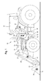
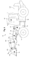
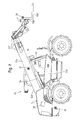
- FIG. 1 and 2 show an agricultural machine 10 with a vehicle in the form of a tractor 12 in combination with a lifting device in the form of a front loader 14.
- the front loader 14 is coupled via a connected to a frame 16 of the tractor console 18 and a connecting mast 20 to the tractor 12.
- the front loader 14 has a rocker 22 which is articulated via hydraulic cylinders 24 pivotally connected to the connecting mast 20.
- a tool holder 26 is arranged, which is articulated via a further hydraulic cylinder 28 pivotally connected to the rocker 22.
- Attached to the tool holder 26 is an attachment or tool in the form of a loader bucket 30.
- the front loader 14 is provided in the region of the rocker 22 with a first acceleration sensor 32.
- a further acceleration sensor 34 is provided in the area of the loader bucket 30, a further acceleration sensor 34 is provided. Furthermore, the tractor 12 is provided with an acceleration sensor which constitutes a reference sensor 35 mounted in the region of the bracket 18 (or at any other point on the tractor 12).
- the acceleration sensor 34 positioned in the region of the loader blade 30 can likewise be arranged directly on the tool holder 26, whereby one and the same Acceleration sensor 34 could be used for the position determination of various tools.
- a further reference sensor 36 shown in the form of a gyroscope or yaw rate sensor, which can be used for improved reference measurement and is positioned on the vehicle or tractor 12. For example, due to the different positioning of accelerometers 32, 34 and reference sensors 35, 36, creeping errors can be more accurately compensated.
- a 3-axis gyroscope with integrated accelerometer can measure all 6 degrees of freedom of a vehicle as a reference.
- Such an additional reference sensor 36 can in all of the here with reference to FIGS. 1 to 7 described embodiments can be used.
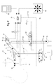
- the tractor 12 further comprises an electronic control unit 38 arranged in the region of the cabin, which is connected to an input module 40.
- the input module 40 allows an operator to input control or reference data that may be supplied to the electronic control unit 38, or in response to which the control unit 38 executes programmable control instructions.
- the control unit 38 to the corresponding via electronic sensor lines 42 (see FIG. 2 ) connected to the acceleration sensors 32, 34, 35 and reference sensor 36 and via electronic control lines 44, 45 with controllable hydraulic switching valves 46, 48, via which a hydraulic flow for operating the hydraulic cylinders 24, 28th is controllable.
- the switching valves 46, 48 are preferably designed as a solenoid-inductive proportional valves.
- the electronic control unit 38 is also connected to an operating lever 50, for example a joystick, via which control signals for actuating the hydraulic switching valves 46, 48 can be triggered by an operator.
- an operating lever 50 for example a joystick
- a hydraulic reservoir 52 and a hydraulic pump 54 are provided, which are respectively connected via hydraulic connecting lines 56, 58 and via the hydraulic switching valves 46, 48 with the hydraulic cylinders 24, 28.
- the positioning of the lifting device 14 or of the attachment 30 is effected by the existing sensor system (32, 34, 35, 36, 38) such that a reference acceleration vector is generated by the reference sensor 35 and supplied to the electronic control unit 38.
- the acceleration sensor 32 positioned on the lifting device (front loader) and the acceleration sensor 34 positioned on the attachment (loader bucket) respectively generate a positional acceleration vector, which are also supplied to the electronic control unit.
- the vectors supplied to the control unit 38 are set in relation, from which a relatively accurate position determination of the lifting device 14 or of the attachment 30 in relation to the vehicle can be determined. Based on the signals of an optionally provided reference sensor 36, the accuracy of the position determination can be additionally increased, as already described.
- the foundation for a control of the hydraulic control valves 46, 48 and the hydraulic cylinder 24, 28 is set by the electronic control unit 38, wherein the electronic control unit 38 of a Operator can be supplied by the input module 40 with corresponding target variables or control variables.
- corresponding control algorithms are stored in the electronic control unit 38.
- the input may be for a maximum height of the implement 30, or for a minimum height.
- Another example would be to specify a preferred working position for the attachment 30, so that, for example, the blade 30 of the front loader 14 is always guided parallel to the ground surface in the raised position in order to ensure, for example, the lowest possible loss of spilled bulk material when moving bulk goods.
- a loss is caused by changes in position of the implement 30 in vehicle position change due to braking, acceleration, rebound or rebound or even when driving over bumps.
- the electronic control unit 38 generates a corresponding control signal which is supplied to the associated hydraulic control valve 48 for the corresponding actuation or actuation of the hydraulic cylinder 28.
- FIGS. 3 to 7 Further embodiments of the invention are shown, wherein the basis FIG. 2 as described above, according to the functional relationships described in FIGS. 3 to 7 illustrated embodiments are applicable. On a new functional description of the position determination for lifting device and attachment is thus omitted. For equivalent functional components were therefore in the FIGS. 3 to 7 the same reference numerals.
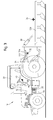
- FIG. 3 shows FIG. 3 an agricultural machine 10 with a vehicle in the form of a tractor 12 in combination with a lifting device in the form of a three-point hitch 114.
- the three-point hitch 114 is connected via a mounting frame (not shown) at the rear with a frame 16 of the tractor 12.
- the three-point hitch 114 has links 122, which are articulated via hydraulic cylinders 24 pivotally mounted on the mounting frame.
- an attachment in the form of a cultivator 130 is arranged, which is articulated via a further hydraulic cylinder 28 pivotally.
- the three-point hitch 114 is provided in the region of the links 122 with a first acceleration sensor 32. In the area of the tillage implement 130, a further acceleration sensor 34 is provided.
- the tractor 12 is provided with an acceleration sensor which constitutes a reference sensor 35 mounted in the region of the frame 16 (or at any other point on the tractor 12).
- the tractor 12 further comprises an electronic control unit 38 arranged in the area of a car 37 and connected to an input module 40.
- the position determination of Lifting device 114 and the attachment 130 is carried out by the existing sensors according to the above description with respect to FIG. 2 , wherein the components with the reference numerals 14 and 30 according to the embodiment to FIG. 3 are to be replaced by the components with the reference numerals 114 and 130. Other components, such as the tool holder 26, are eliminated.
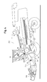
- FIG. 4 another embodiment is shown. It shows an agricultural machine 10 with a vehicle in the form of a harvester 212 in combination with a lifting device in the form of an attachment stand 214.
- the attachment rod 214 is connected at the front of the harvester 212 to a frame 16 of the harvester 212.
- the attachment rod 214 has links 222, which are articulated via hydraulic cylinders 24 pivotally connected to the frame 16.
- At the front end of the link 222 an attachment in the form of a header 230 is arranged.
- the attachment rod 214 is provided with a first acceleration sensor 32 in the area of the links 222.
- a second acceleration sensor 34 is not provided in this case since the harvesting attachment 230 is not pivotably coupled to the attachment rod 214 and thus also not via a hydraulic cylinder 28 according to FIG FIG. 3 is operable.
- the harvester 212 is provided with an acceleration sensor which constitutes a reference sensor 35 mounted in the region of the frame 16 (or at any other location on the harvester 212) (optionally, as in FIG FIG. 1 and 2 shown, another reference sensor 36 may be provided in the region of the frame 16 in the form of a gyroscope or yaw rate sensor (in the FIGS. 3 to 7 not shown)).
- the harvester 212 further includes one in the region of Cabin 37 arranged electronic control unit 38 which is connected to an input module 40.
- the position of the attachment rod 214 and the attachment 230 is determined by the existing sensors according to the above description with respect to FIG. 2 , wherein the components with the reference numerals 12, 14 and 30 according to the embodiment to FIG. 4 are to be replaced by the components with the reference numerals 212, 214 and 230.
- Other components off FIG. 3 Such as the tool holder 26, the hydraulic cylinder 28, the hydraulic valve 48, the associated hydraulic connecting lines 58, and the associated electronic sensor and control lines 42, 45 account for lack of presence in relation to the embodiment FIG. 4 ,
- FIG. 5 another embodiment is shown. It shows an agricultural machine 10 with a vehicle in the form of a self-propelled sprayer 312 in combination with a lifting device in the form of a parallelogram linkage 314.
- the parallelogram linkage 314 is connected at the rear of the field sprayer 312 to a frame 16 of the field sprayer 212.
- the parallelogram linkage 314 has links 322 which are pivotably articulated to the frame 16 via hydraulic cylinders 24.
- a device receptacle 326 is provided at the rear end of the handlebar 322.
- an attachment in the form of a syringe rod 330 is arranged, which is articulated via a further hydraulic cylinder 28 about a longitudinal axis of the machine 10 pivotally connected to the device receptacle 326.
- the parallelogram linkage 314 is provided with a first acceleration sensor 32 in the area of the links 322.
- a further acceleration sensor 34 is provided in the area of the spray boom 330.
- the field sprayer 312 is with a Acceleration sensor provided, which is a in the region of the frame 16 (or at any other location on the field sprayer 312) attached reference sensor 35 (where appropriate, as in FIG.
- another reference sensor 36 may be provided in the region of the frame 16 in the form of a gyroscope or yaw rate sensor (in the FIGS. 3 to 7 not shown)).
- the field sprayer 312 further comprises an electronic control unit 38 which is arranged in the region of a car 37 and which is connected to an input module 40.
- the position determination of the parallelogram linkage 314 or of the spray boom linkage 330 is effected by the existing sensors according to the above description with reference to FIG FIG. 2 , wherein the components with the reference numerals 12, 14, 26 and 30 according to the embodiment to FIG. 5 are to be replaced by the components with the reference numerals 312, 314, 326 and 330.
- FIG. 6 another embodiment is shown. It shows an agricultural machine 10 with a vehicle in the form of a wheel loader vehicle 412 in combination with a lifting device in the form of a loading device 414.
- the loading device 414 is connected at the front of the wheel loader vehicle 412 to a frame 16 of the wheel loader vehicle 412.
- the loading device 414 has a rocker 422, which is articulated via hydraulic cylinders 24 pivotally connected to the frame 16.
- a device or tool holder 426 is provided, to which an attachment in the form of a loader bucket 430 is coupled, wherein the tool holder 426 is articulated via a further hydraulic cylinder 28 pivotally.
- the charging device 414 is provided with a first acceleration sensor 32 in the area of the rocker 422. In the area of the loader bucket 430 is another Acceleration sensor 34 is provided. Further, the wheel loader vehicle 412 is provided with an acceleration sensor which constitutes a reference sensor 35 mounted in the region of the frame 16 (or at any other location on the wheel loader vehicle 412) FIG. 1 and 2 shown, another reference sensor 36 may be provided in the region of the frame 16 in the form of a gyroscope or yaw rate sensor (in the FIGS. 3 to 7 not shown)). The wheel loader vehicle 412 further comprises an electronic control unit 38 arranged in the area of a car 37 and connected to an input module 40.
- the position determination of the charging device 414 or the loader bucket 430 is effected by the existing sensors according to the above description with reference to FIG FIG. 2 , wherein the components with the reference numerals 12, 14, 26 and 30 according to the embodiment to FIG. 6 are to be replaced by the components with the reference numerals 412, 414, 426 and 430.
- FIG. 7 another embodiment is shown. It shows an agricultural machine 10 with a vehicle in the form of a telescopic loader vehicle 512 in combination with a lifting device in the form of a telescopic boom 514.
- the telescopic boom 514 is connected to a frame 16 of the telehandler vehicle 512.
- the telescopic boom 514 comprises a plurality of telescopically guided boom elements 522 and is pivotably articulated via a hydraulic cylinder 24 to the frame 16.
- a tool or tool holder 526 is provided, to which an attachment in the form of a fork 530 is coupled, wherein the tool holder 526 is articulated via a further hydraulic cylinder 28 pivotally.
- the telescopic boom 514 is in the range of Boom elements 522 provided with a first acceleration sensor 32. In the area of the fork 530, a further acceleration sensor 34 is provided. Furthermore, the telescopic loader vehicle 512 is provided with an acceleration sensor which constitutes a reference sensor 35 mounted in the region of the frame 16 (or at any other location on the telescopic loader vehicle 512) FIG. 1 and 2 shown, another reference sensor 36 may be provided in the region of the frame 16 in the form of a gyroscope or yaw rate sensor (in the FIGS. 3 to 7 not shown)). The telehandler vehicle 512 further comprises an electronic control unit 38 arranged in the region of a car 37 and connected to an input module 40.
- the position of the telescopic boom 514 or the fork 530 is determined by the existing sensors according to the above description with respect to FIG. 2 , wherein the components with the reference numerals 12, 14, 26 and 30 according to the embodiment to FIG. 7 are to be replaced by the components with reference numerals 512, 514, 526 and 530.
Landscapes
- Engineering & Computer Science (AREA)
- Mechanical Engineering (AREA)
- Structural Engineering (AREA)
- Life Sciences & Earth Sciences (AREA)
- Civil Engineering (AREA)
- Transportation (AREA)
- General Engineering & Computer Science (AREA)
- Chemical & Material Sciences (AREA)
- Combustion & Propulsion (AREA)
- Mining & Mineral Resources (AREA)
- Geology (AREA)
- Soil Sciences (AREA)
- Environmental Sciences (AREA)
- Lifting Devices For Agricultural Implements (AREA)
- Operation Control Of Excavators (AREA)
Applications Claiming Priority (1)
| Application Number | Priority Date | Filing Date | Title |
|---|---|---|---|
| DE102007045846A DE102007045846A1 (de) | 2007-09-26 | 2007-09-26 | Landwirtschaftliche Maschine und Verfahren zur Positionsbestimmung |
Publications (3)
| Publication Number | Publication Date |
|---|---|
| EP2042276A2 true EP2042276A2 (fr) | 2009-04-01 |
| EP2042276A3 EP2042276A3 (fr) | 2009-05-27 |
| EP2042276B1 EP2042276B1 (fr) | 2011-11-16 |
Family
ID=40120436
Family Applications (1)
| Application Number | Title | Priority Date | Filing Date |
|---|---|---|---|
| EP08162955A Revoked EP2042276B1 (fr) | 2007-09-26 | 2008-08-26 | Machine agricole et procédé de détermination de position |
Country Status (5)
| Country | Link |
|---|---|
| US (1) | US8155844B2 (fr) |
| EP (1) | EP2042276B1 (fr) |
| AT (1) | ATE533598T1 (fr) |
| DE (1) | DE102007045846A1 (fr) |
| ES (1) | ES2377675T3 (fr) |
Cited By (13)
| Publication number | Priority date | Publication date | Assignee | Title |
|---|---|---|---|---|
| WO2010121713A1 (fr) * | 2009-04-20 | 2010-10-28 | Robert Bosch Gmbh | Engin de chantier mobile équipé d'un dispositif de régulation de position d'un bras de travail et procédé pour réguler la position d'un bras de travail d'un engin de chantier mobile |
| EP2638795A1 (fr) * | 2012-03-13 | 2013-09-18 | CLAAS Saulgau GmbH | Dispositif de cueillette destiné à recevoir des plantes |
| EP2936980A1 (fr) * | 2014-04-23 | 2015-10-28 | Robert Bosch Gmbh | Pulvérisateur à cultures |
| DE102015105217A1 (de) * | 2015-04-07 | 2016-10-13 | Claas Saulgau Gmbh | Verfahren zum Betreiben eines landwirtschaftlichen Erntefahrzeugs und Steuerungseinrichtung |
| EP3007553B1 (fr) | 2013-09-18 | 2017-03-01 | HORSCH LEEB Application Systems GmbH | Dispositif de distribution de substances actives liquides et/ou solides et procédé de commande d'un tel dispositif |
| EP2591657B1 (fr) | 2011-11-08 | 2017-06-28 | HORSCH LEEB Application Systems GmbH | Dispositif mobile destiné à sortir des agents actifs liquides et/ou solides et procédé de commande du dispositif |
| EP3251485A1 (fr) * | 2016-05-30 | 2017-12-06 | Deere & Company | Système et procédé de surveillance et/ou de contrôle de l'état de marche d'une machine de travail agricole automotrice |
| US9932213B2 (en) | 2014-09-15 | 2018-04-03 | Crown Equipment Corporation | Lift truck with optical load sensing structure |
| GB2557643A (en) * | 2016-12-14 | 2018-06-27 | Caterpillar Inc | Pro-active machine damage limitation system |
| EP3289847B1 (fr) | 2016-09-01 | 2020-01-01 | Deere & Company | Arrangement destiné à influencer l'emplacement d'un équipement agricole |
| EP2559332B2 (fr) † | 2011-08-15 | 2021-01-13 | Amazonen-Werke H. Dreyer GmbH & Co. KG | Machine de répartition agricole |
| EP3797568A1 (fr) * | 2019-09-25 | 2021-03-31 | Kubota Corporation | Véhicule de déplacement |
| EP4108837A1 (fr) * | 2021-06-23 | 2022-12-28 | Liebherr-Hydraulikbagger GmbH | Système et procédé de localisation d'un outil auxiliaire |
Families Citing this family (37)
| Publication number | Priority date | Publication date | Assignee | Title |
|---|---|---|---|---|
| JP2009197425A (ja) * | 2008-02-20 | 2009-09-03 | Komatsu Ltd | 建設機械 |
| US8463508B2 (en) * | 2009-12-18 | 2013-06-11 | Caterpillar Inc. | Implement angle correction system and associated loader |
| US8594896B2 (en) * | 2009-12-18 | 2013-11-26 | Caterpillar Sarl | Lift arm control system |
| DK201100331A (en) * | 2011-04-29 | 2012-10-30 | Univ Syddansk | Active damping system for a spray boom |
| DE102012016004B4 (de) * | 2012-08-11 | 2017-12-28 | Identec Solutions Ag | Verfahren und Vorrichtung zur Erfassung der Anwesenheit von steinbrechenden Werkzeugen an Erdbewegungsmaschinen |
| US20140088837A1 (en) * | 2012-09-21 | 2014-03-27 | Erric L. Heitmann | Vehicle With Solicited Carriage Descent |
| DE102013203826A1 (de) * | 2013-03-06 | 2014-09-11 | Deere & Company | Arbeitsmaschine mit Hubvorrichtung und Wiegeeinrichtung |
| EP3065530B1 (fr) | 2013-11-10 | 2022-03-30 | HORSCH LEEB Application Systems GmbH | Dispositif pour distribuer des substances actives liquides et/ou solides et procédé de commande d'un tel dispositif |
| CN103950868A (zh) * | 2014-04-23 | 2014-07-30 | 福建晋工机械有限公司 | 一种前移式叉装车的驱动机构 |
| EP3245340A1 (fr) * | 2015-01-15 | 2017-11-22 | Modustri LLC | Appareil de surveillance configurable et système de gestion de pièces |
| DE102015102975A1 (de) | 2015-03-02 | 2016-09-08 | Horsch Leeb Application Systems Gmbh | Vorrichtung zum Ausbringen von flüssigen und/oder festen Wirkstoffen und Verfahren zur Steuerung einer solchen Vorrichtung |
| DE102015204992B3 (de) * | 2015-03-19 | 2016-04-28 | Hochschule für Technik und Wirtschaft Dresden | Vorrichtung zum Ausgleichen von Gier- und/oder Wankbewegungen einer Feldspritze |
| AR104232A1 (es) * | 2015-04-13 | 2017-07-05 | Leica Geosystems Pty Ltd | Compensación dinámica del movimiento en maquinarias |
| EP3150052B1 (fr) | 2015-09-30 | 2018-06-13 | CLAAS E-Systems KGaA mbH & Co KG | Machine de récolte de culture |
| US10316489B2 (en) | 2015-12-07 | 2019-06-11 | Kubota Cororation | Work machine and hydraulic system for work machine |
| US9968033B2 (en) * | 2016-06-21 | 2018-05-15 | Macdon Industries Ltd. | Crop machine with an electronically controlled hydraulic cylinder flotation system |
| US10981763B2 (en) | 2017-11-07 | 2021-04-20 | Deere & Company | Work tool leveling system |
| US10829907B2 (en) | 2018-02-28 | 2020-11-10 | Deere & Company | Method of limiting flow through sensed kinetic energy |
| US11293168B2 (en) | 2018-02-28 | 2022-04-05 | Deere & Company | Method of limiting flow through accelerometer feedback |
| US10648154B2 (en) | 2018-02-28 | 2020-05-12 | Deere & Company | Method of limiting flow in response to sensed pressure |
| US11525238B2 (en) | 2018-02-28 | 2022-12-13 | Deere & Company | Stability control for hydraulic work machine |
| US10954650B2 (en) | 2018-02-28 | 2021-03-23 | Deere & Company | Hydraulic derate stability control |
| US10954654B2 (en) | 2018-02-28 | 2021-03-23 | Deere & Company | Hydraulic derate stability control and calibration |
| US10773665B2 (en) | 2018-10-16 | 2020-09-15 | Cnh Industrial America Llc | System and method for detecting a damage condition associated with an agricultural machine |
| US11512447B2 (en) | 2018-11-06 | 2022-11-29 | Deere & Company | Systems and methods to improve work machine stability based on operating values |
| WO2020185764A1 (fr) * | 2019-03-11 | 2020-09-17 | Cnh Industrial America Llc | Véhicule agricole à hauteur de levage réglable sur la base de l'identification de la table de coupe |
| CN110028022B (zh) * | 2019-05-13 | 2025-06-17 | 浙江加力仓储设备股份有限公司 | 一种液压阀组控制系统及具有其的智能型堆垛车 |
| DE102019115301B4 (de) * | 2019-06-06 | 2024-01-18 | Amazonen-Werke H. Dreyer SE & Co. KG | Steuerungs- und/oder Regelvorrichtung und Verfahren zum Betrieb eines Anbaugerätes an einem Fahrzeug |
| DE102020110367A1 (de) | 2020-04-16 | 2021-10-21 | Horsch Leeb Application Systems Gmbh | System für eine landwirtschaftliche Arbeitsmaschine, Verfahren zum Ermitteln einer Position von Arbeitselementen sowie landwirtschaftliche Arbeitsmaschine |
| DE102020127684A1 (de) * | 2020-10-21 | 2022-04-21 | Amazonen-Werke H. Dreyer SE & Co. KG | Landwirtschaftliches Gerät mit einem Gestänge |
| DE102021203122A1 (de) | 2021-03-29 | 2022-09-29 | Siemens Mobility GmbH | Fahrzeug mit einer Sensoranordnung zur Messung eines Stellwinkels des Stellelementes, Messanordnung und Messverfahren |
| DE102021002610A1 (de) * | 2021-05-18 | 2022-11-24 | Hydac Mobilhydraulik Gmbh | Fahrbare Arbeitsmaschine |
| US11549236B1 (en) | 2021-06-16 | 2023-01-10 | Cnh Industrial America Llc | Work vehicle with improved bi-directional self-leveling functionality and related systems and methods |
| JP7600095B2 (ja) * | 2021-12-28 | 2024-12-16 | 株式会社クボタ | 農業機械、農作業支援システム |
| DE102022103504A1 (de) | 2022-02-15 | 2023-08-17 | Lemken Gmbh & Co. Kg | Fahrzeug-Gerätekombination mit Steckverbindung |
| DE102023108278A1 (de) * | 2023-03-31 | 2024-10-02 | Deere & Company | Ballenpresse und Verfahren zum Betrieb einer Ballenpresse |
| US12529202B2 (en) | 2023-10-19 | 2026-01-20 | Cnh Industrial America Llc | Work vehicle with implement self-leveling functionality including rollback prevention and related systems and methods |
Citations (2)
| Publication number | Priority date | Publication date | Assignee | Title |
|---|---|---|---|---|
| DE19900587A1 (de) | 1999-01-09 | 2000-07-13 | Reiner Foerst | Vorrichtung zur Messung der Positionen und Winkel von Gelenkgliedern eines Bewegungssystems |
| DE19901563A1 (de) | 1999-01-16 | 2000-07-27 | Pfreundt Gmbh & Co Kg | Anordnung zum Wiegen von Nutzlasten |
Family Cites Families (9)
| Publication number | Priority date | Publication date | Assignee | Title |
|---|---|---|---|---|
| US3497014A (en) * | 1967-05-01 | 1970-02-24 | United Aircraft Corp | Automatic blade bite control |
| NL7800648A (nl) * | 1978-01-19 | 1979-07-23 | Lely Nv C Van Der | Trekker. |
| DE3501568A1 (de) * | 1984-03-15 | 1985-09-19 | Mannesmann Rexroth GmbH, 8770 Lohr | Verfahren zur regelung eines anbaugeraets an landwirtschaftlichen schleppern |
| DE4328144C2 (de) | 1993-08-21 | 2001-04-26 | Bosch Gmbh Robert | Vorrichtung zur Gewichtsbestimmung von an einem Schlepper angehängten Lasten und Verfahren dazu |
| DE10000771C2 (de) * | 2000-01-11 | 2003-06-12 | Brueninghaus Hydromatik Gmbh | Vorrichtung und Verfahren zur Lageregelung für Arbeitseinrichtungen mobiler Arbeitsmaschinen |
| DE102004012945A1 (de) * | 2004-03-17 | 2005-10-13 | Cnh Baumaschinen Gmbh | Vorrichtung und Verfahren zur Bewegungstilgung bei Baumaschinen |
| DE102005024676A1 (de) * | 2004-12-21 | 2006-07-06 | Bosch Rexroth Aktiengesellschaft | System zur Lageerfassung und -regelung für Arbeitsarme mobiler Arbeitsmaschinen |
| DE102006016372B3 (de) | 2006-04-05 | 2007-10-31 | Pfreundt Gmbh | Wägemodul eines Radladers |
| US8036797B2 (en) * | 2007-03-20 | 2011-10-11 | Deere & Company | Method and system for controlling a vehicle for loading or digging material |
-
2007
- 2007-09-26 DE DE102007045846A patent/DE102007045846A1/de not_active Withdrawn
-
2008
- 2008-08-14 US US12/191,413 patent/US8155844B2/en active Active
- 2008-08-26 ES ES08162955T patent/ES2377675T3/es active Active
- 2008-08-26 EP EP08162955A patent/EP2042276B1/fr not_active Revoked
- 2008-08-26 AT AT08162955T patent/ATE533598T1/de active
Patent Citations (2)
| Publication number | Priority date | Publication date | Assignee | Title |
|---|---|---|---|---|
| DE19900587A1 (de) | 1999-01-09 | 2000-07-13 | Reiner Foerst | Vorrichtung zur Messung der Positionen und Winkel von Gelenkgliedern eines Bewegungssystems |
| DE19901563A1 (de) | 1999-01-16 | 2000-07-27 | Pfreundt Gmbh & Co Kg | Anordnung zum Wiegen von Nutzlasten |
Cited By (23)
| Publication number | Priority date | Publication date | Assignee | Title |
|---|---|---|---|---|
| CN102459766A (zh) * | 2009-04-20 | 2012-05-16 | 罗伯特·博世有限公司 | 具有工作臂的位置控制装置的移动工作机械和用于控制移动工作机械的工作臂的位置的方法 |
| US9151013B2 (en) | 2009-04-20 | 2015-10-06 | Robert Bosch Gmbh | Mobile working machine comprising a position control device of a working arm, and method for controlling the position of a working arm of a mobile working machine |
| CN102459766B (zh) * | 2009-04-20 | 2015-11-25 | 罗伯特·博世有限公司 | 具有工作臂的位置控制装置的移动工作机械和用于控制移动工作机械的工作臂的位置的方法 |
| WO2010121713A1 (fr) * | 2009-04-20 | 2010-10-28 | Robert Bosch Gmbh | Engin de chantier mobile équipé d'un dispositif de régulation de position d'un bras de travail et procédé pour réguler la position d'un bras de travail d'un engin de chantier mobile |
| EP2559332B2 (fr) † | 2011-08-15 | 2021-01-13 | Amazonen-Werke H. Dreyer GmbH & Co. KG | Machine de répartition agricole |
| EP2591657B1 (fr) | 2011-11-08 | 2017-06-28 | HORSCH LEEB Application Systems GmbH | Dispositif mobile destiné à sortir des agents actifs liquides et/ou solides et procédé de commande du dispositif |
| EP2638795A1 (fr) * | 2012-03-13 | 2013-09-18 | CLAAS Saulgau GmbH | Dispositif de cueillette destiné à recevoir des plantes |
| US10470361B2 (en) | 2013-09-18 | 2019-11-12 | Horsch Leeb Application Systems Gmbh | Device for discharging fluid and/or solid active materials and method for controlling such a device |
| EP3007553B2 (fr) † | 2013-09-18 | 2022-12-28 | HORSCH LEEB Application Systems GmbH | Dispositif de distribution de substances actives liquides et/ou solides et procédé de commande d'un tel dispositif |
| EP3007553B1 (fr) | 2013-09-18 | 2017-03-01 | HORSCH LEEB Application Systems GmbH | Dispositif de distribution de substances actives liquides et/ou solides et procédé de commande d'un tel dispositif |
| EP3183963B1 (fr) | 2013-09-18 | 2018-05-16 | HORSCH LEEB Application Systems GmbH | Dispositif d'extraction de liquides et/ou d'agents actifs solides et procédé de commande d'un tel dispositif |
| EP2936980A1 (fr) * | 2014-04-23 | 2015-10-28 | Robert Bosch Gmbh | Pulvérisateur à cultures |
| US9932213B2 (en) | 2014-09-15 | 2018-04-03 | Crown Equipment Corporation | Lift truck with optical load sensing structure |
| DE102015105217A1 (de) * | 2015-04-07 | 2016-10-13 | Claas Saulgau Gmbh | Verfahren zum Betreiben eines landwirtschaftlichen Erntefahrzeugs und Steuerungseinrichtung |
| US10448556B2 (en) | 2016-05-30 | 2019-10-22 | Deere & Company | Arrangement and method for monitoring and/or controlling the driving state of a self-propelled agricultural working machine |
| EP3251485A1 (fr) * | 2016-05-30 | 2017-12-06 | Deere & Company | Système et procédé de surveillance et/ou de contrôle de l'état de marche d'une machine de travail agricole automotrice |
| EP3289847B1 (fr) | 2016-09-01 | 2020-01-01 | Deere & Company | Arrangement destiné à influencer l'emplacement d'un équipement agricole |
| EP3289847B2 (fr) † | 2016-09-01 | 2022-09-28 | Deere & Company | Arrangement destiné à influencer l'emplacement d'un équipement agricole |
| GB2557643A (en) * | 2016-12-14 | 2018-06-27 | Caterpillar Inc | Pro-active machine damage limitation system |
| GB2557643B (en) * | 2016-12-14 | 2019-12-18 | Caterpillar Inc | Pro-active machine damage limitation system |
| EP3797568A1 (fr) * | 2019-09-25 | 2021-03-31 | Kubota Corporation | Véhicule de déplacement |
| US11533901B2 (en) | 2019-09-25 | 2022-12-27 | Kubota Corporation | Traveling vehicle |
| EP4108837A1 (fr) * | 2021-06-23 | 2022-12-28 | Liebherr-Hydraulikbagger GmbH | Système et procédé de localisation d'un outil auxiliaire |
Also Published As
| Publication number | Publication date |
|---|---|
| EP2042276B1 (fr) | 2011-11-16 |
| ES2377675T3 (es) | 2012-03-29 |
| US8155844B2 (en) | 2012-04-10 |
| DE102007045846A1 (de) | 2009-04-02 |
| US20090082930A1 (en) | 2009-03-26 |
| EP2042276A3 (fr) | 2009-05-27 |
| ATE533598T1 (de) | 2011-12-15 |
Similar Documents
| Publication | Publication Date | Title |
|---|---|---|
| EP2042276B1 (fr) | Machine agricole et procédé de détermination de position | |
| EP3289847B2 (fr) | Arrangement destiné à influencer l'emplacement d'un équipement agricole | |
| EP3563667B1 (fr) | Procédé de distribution de produit de récolte | |
| EP3903549B1 (fr) | Machine de traitement du sol, de préférence herse-étrille agricole et procédé de réglage d'une force de précontrainte sur une herse-étrille | |
| WO2019238330A1 (fr) | Procédé et dispositif permettant de faire fonctionner des machines de travail à fonctionnement autonome | |
| DE112016000090T5 (de) | Baumaschinensteuerungssystem, baumaschine und baumaschinensteuerungsverfahren | |
| DE112017002603B4 (de) | Steuerungssystem für eine baumaschine, baumaschine und steuerverfahren für eine baumaschine | |
| DE112016000070B4 (de) | Arbeitsmaschinensteuersystem, arbeitsmaschine und arbeitsmaschinensteuerverfahren | |
| EP3300558B1 (fr) | Dispositif et procédé de réglage du fonctionnement d'un appareil isolé hydraulique d'un véhicule | |
| DE10120732A1 (de) | Anbauschnittstelle zwischen Arbeitsfahrzeug und Arbeitsgeräten sowie Steuereinrichtung | |
| DE112016000072T5 (de) | Baumaschinensteuersystem, baumaschine und baumaschinensteuerverfahren | |
| DE102020124867B4 (de) | Verbesserte Hydraulikvorrichtung | |
| DE102020212648A1 (de) | Elektrohydraulische Anbaugerätesteuerung System und Verfahren | |
| EP4052550B1 (fr) | Dispositif de compensation de la suspension latérale pour la viticulture | |
| DE10011499A1 (de) | Vorrichtung zur Bodenkopierung für Vorsatzgeräte an Erntemaschinen | |
| EP3533307B1 (fr) | Procédé de commande d'un bras supérieur hydraulique d'un attelage trois points | |
| AT519979B1 (de) | Dreipunktkupplung | |
| DE102018205092A1 (de) | Fahrzeug mit Erfassungseinrichtung zur Positionserfassung eines Anbaugeräts | |
| DE102020106738A1 (de) | Kompensationssystem für eine Landmaschine, sowie Verteilmaschine und Verfahren zur Kompensation von Bodenunebenheiten für eine Landmaschine | |
| DE102017108997A1 (de) | Verfahren zum Einstellen der Arbeitstiefe eines landwirtschaftlichen Bodenbearbeitungsgeräts | |
| DE102019115301B4 (de) | Steuerungs- und/oder Regelvorrichtung und Verfahren zum Betrieb eines Anbaugerätes an einem Fahrzeug | |
| DE102018103862A1 (de) | Aufhängung für eine landwirtschaftliche Maschine und Verfahren zum Betreiben einer landwirtschaftlichen Maschine | |
| EP3498065B1 (fr) | Procédé de commande de mouvement d'un relevage à trois points d'un tracteur | |
| EP3735810A1 (fr) | Dispositif d'accouplement pour un attelage | |
| EP1416095A1 (fr) | Véhicule de travail, en particulier une pelle rétro et/ou un véhicule avec un chargeur frontal |
Legal Events
| Date | Code | Title | Description |
|---|---|---|---|
| PUAI | Public reference made under article 153(3) epc to a published international application that has entered the european phase |
Free format text: ORIGINAL CODE: 0009012 |
|
| AK | Designated contracting states |
Kind code of ref document: A2 Designated state(s): AT BE BG CH CY CZ DE DK EE ES FI FR GB GR HR HU IE IS IT LI LT LU LV MC MT NL NO PL PT RO SE SI SK TR |
|
| AX | Request for extension of the european patent |
Extension state: AL BA MK RS |
|
| PUAL | Search report despatched |
Free format text: ORIGINAL CODE: 0009013 |
|
| AK | Designated contracting states |
Kind code of ref document: A3 Designated state(s): AT BE BG CH CY CZ DE DK EE ES FI FR GB GR HR HU IE IS IT LI LT LU LV MC MT NL NO PL PT RO SE SI SK TR |
|
| AX | Request for extension of the european patent |
Extension state: AL BA MK RS |
|
| RIC1 | Information provided on ipc code assigned before grant |
Ipc: A01B 63/10 20060101ALI20090422BHEP Ipc: G01G 19/08 20060101ALI20090422BHEP Ipc: G01P 15/18 20060101ALI20090422BHEP Ipc: B25J 13/08 20060101AFI20090106BHEP |
|
| 17P | Request for examination filed |
Effective date: 20091127 |
|
| AKX | Designation fees paid |
Designated state(s): AT BE BG CH CY CZ DE DK EE ES FI FR GB GR HR HU IE IS IT LI LT LU LV MC MT NL NO PL PT RO SE SI SK TR |
|
| 17Q | First examination report despatched |
Effective date: 20100111 |
|
| GRAP | Despatch of communication of intention to grant a patent |
Free format text: ORIGINAL CODE: EPIDOSNIGR1 |
|
| GRAS | Grant fee paid |
Free format text: ORIGINAL CODE: EPIDOSNIGR3 |
|
| GRAA | (expected) grant |
Free format text: ORIGINAL CODE: 0009210 |
|
| AK | Designated contracting states |
Kind code of ref document: B1 Designated state(s): AT BE BG CH CY CZ DE DK EE ES FI FR GB GR HR HU IE IS IT LI LT LU LV MC MT NL NO PL PT RO SE SI SK TR |
|
| REG | Reference to a national code |
Ref country code: GB Ref legal event code: FG4D Free format text: NOT ENGLISH |
|
| REG | Reference to a national code |
Ref country code: CH Ref legal event code: EP |
|
| REG | Reference to a national code |
Ref country code: IE Ref legal event code: FG4D Free format text: LANGUAGE OF EP DOCUMENT: GERMAN |
|
| REG | Reference to a national code |
Ref country code: DE Ref legal event code: R096 Ref document number: 502008005584 Country of ref document: DE Effective date: 20120119 |
|
| REG | Reference to a national code |
Ref country code: NL Ref legal event code: VDEP Effective date: 20111116 |
|
| REG | Reference to a national code |
Ref country code: SE Ref legal event code: TRGR |
|
| REG | Reference to a national code |
Ref country code: NO Ref legal event code: T2 Effective date: 20111116 |
|
| REG | Reference to a national code |
Ref country code: ES Ref legal event code: FG2A Ref document number: 2377675 Country of ref document: ES Kind code of ref document: T3 Effective date: 20120329 |
|
| LTIE | Lt: invalidation of european patent or patent extension |
Effective date: 20111116 |
|
| PG25 | Lapsed in a contracting state [announced via postgrant information from national office to epo] |
Ref country code: IS Free format text: LAPSE BECAUSE OF FAILURE TO SUBMIT A TRANSLATION OF THE DESCRIPTION OR TO PAY THE FEE WITHIN THE PRESCRIBED TIME-LIMIT Effective date: 20120316 Ref country code: LT Free format text: LAPSE BECAUSE OF FAILURE TO SUBMIT A TRANSLATION OF THE DESCRIPTION OR TO PAY THE FEE WITHIN THE PRESCRIBED TIME-LIMIT Effective date: 20111116 |
|
| PG25 | Lapsed in a contracting state [announced via postgrant information from national office to epo] |
Ref country code: GR Free format text: LAPSE BECAUSE OF FAILURE TO SUBMIT A TRANSLATION OF THE DESCRIPTION OR TO PAY THE FEE WITHIN THE PRESCRIBED TIME-LIMIT Effective date: 20120217 Ref country code: PT Free format text: LAPSE BECAUSE OF FAILURE TO SUBMIT A TRANSLATION OF THE DESCRIPTION OR TO PAY THE FEE WITHIN THE PRESCRIBED TIME-LIMIT Effective date: 20120316 Ref country code: LV Free format text: LAPSE BECAUSE OF FAILURE TO SUBMIT A TRANSLATION OF THE DESCRIPTION OR TO PAY THE FEE WITHIN THE PRESCRIBED TIME-LIMIT Effective date: 20111116 Ref country code: NL Free format text: LAPSE BECAUSE OF FAILURE TO SUBMIT A TRANSLATION OF THE DESCRIPTION OR TO PAY THE FEE WITHIN THE PRESCRIBED TIME-LIMIT Effective date: 20111116 Ref country code: SI Free format text: LAPSE BECAUSE OF FAILURE TO SUBMIT A TRANSLATION OF THE DESCRIPTION OR TO PAY THE FEE WITHIN THE PRESCRIBED TIME-LIMIT Effective date: 20111116 Ref country code: HR Free format text: LAPSE BECAUSE OF FAILURE TO SUBMIT A TRANSLATION OF THE DESCRIPTION OR TO PAY THE FEE WITHIN THE PRESCRIBED TIME-LIMIT Effective date: 20111116 Ref country code: PL Free format text: LAPSE BECAUSE OF FAILURE TO SUBMIT A TRANSLATION OF THE DESCRIPTION OR TO PAY THE FEE WITHIN THE PRESCRIBED TIME-LIMIT Effective date: 20111116 |
|
| REG | Reference to a national code |
Ref country code: IE Ref legal event code: FD4D |
|
| PG25 | Lapsed in a contracting state [announced via postgrant information from national office to epo] |
Ref country code: CY Free format text: LAPSE BECAUSE OF FAILURE TO SUBMIT A TRANSLATION OF THE DESCRIPTION OR TO PAY THE FEE WITHIN THE PRESCRIBED TIME-LIMIT Effective date: 20111116 |
|
| PG25 | Lapsed in a contracting state [announced via postgrant information from national office to epo] |
Ref country code: CZ Free format text: LAPSE BECAUSE OF FAILURE TO SUBMIT A TRANSLATION OF THE DESCRIPTION OR TO PAY THE FEE WITHIN THE PRESCRIBED TIME-LIMIT Effective date: 20111116 Ref country code: IE Free format text: LAPSE BECAUSE OF FAILURE TO SUBMIT A TRANSLATION OF THE DESCRIPTION OR TO PAY THE FEE WITHIN THE PRESCRIBED TIME-LIMIT Effective date: 20111116 Ref country code: SK Free format text: LAPSE BECAUSE OF FAILURE TO SUBMIT A TRANSLATION OF THE DESCRIPTION OR TO PAY THE FEE WITHIN THE PRESCRIBED TIME-LIMIT Effective date: 20111116 Ref country code: BG Free format text: LAPSE BECAUSE OF FAILURE TO SUBMIT A TRANSLATION OF THE DESCRIPTION OR TO PAY THE FEE WITHIN THE PRESCRIBED TIME-LIMIT Effective date: 20120216 Ref country code: EE Free format text: LAPSE BECAUSE OF FAILURE TO SUBMIT A TRANSLATION OF THE DESCRIPTION OR TO PAY THE FEE WITHIN THE PRESCRIBED TIME-LIMIT Effective date: 20111116 Ref country code: DK Free format text: LAPSE BECAUSE OF FAILURE TO SUBMIT A TRANSLATION OF THE DESCRIPTION OR TO PAY THE FEE WITHIN THE PRESCRIBED TIME-LIMIT Effective date: 20111116 |
|
| PLBI | Opposition filed |
Free format text: ORIGINAL CODE: 0009260 |
|
| PG25 | Lapsed in a contracting state [announced via postgrant information from national office to epo] |
Ref country code: RO Free format text: LAPSE BECAUSE OF FAILURE TO SUBMIT A TRANSLATION OF THE DESCRIPTION OR TO PAY THE FEE WITHIN THE PRESCRIBED TIME-LIMIT Effective date: 20111116 |
|
| PLAX | Notice of opposition and request to file observation + time limit sent |
Free format text: ORIGINAL CODE: EPIDOSNOBS2 |
|
| 26 | Opposition filed |
Opponent name: ALOE AKTIEBOLAG Effective date: 20120816 |
|
| REG | Reference to a national code |
Ref country code: DE Ref legal event code: R026 Ref document number: 502008005584 Country of ref document: DE Effective date: 20120816 |
|
| PLBB | Reply of patent proprietor to notice(s) of opposition received |
Free format text: ORIGINAL CODE: EPIDOSNOBS3 |
|
| BERE | Be: lapsed |
Owner name: DEERE & CY Effective date: 20120831 |
|
| REG | Reference to a national code |
Ref country code: CH Ref legal event code: PL |
|
| PG25 | Lapsed in a contracting state [announced via postgrant information from national office to epo] |
Ref country code: MC Free format text: LAPSE BECAUSE OF NON-PAYMENT OF DUE FEES Effective date: 20120831 |
|
| PG25 | Lapsed in a contracting state [announced via postgrant information from national office to epo] |
Ref country code: CH Free format text: LAPSE BECAUSE OF NON-PAYMENT OF DUE FEES Effective date: 20120831 Ref country code: LI Free format text: LAPSE BECAUSE OF NON-PAYMENT OF DUE FEES Effective date: 20120831 |
|
| PG25 | Lapsed in a contracting state [announced via postgrant information from national office to epo] |
Ref country code: BE Free format text: LAPSE BECAUSE OF NON-PAYMENT OF DUE FEES Effective date: 20120831 |
|
| PG25 | Lapsed in a contracting state [announced via postgrant information from national office to epo] |
Ref country code: FI Free format text: LAPSE BECAUSE OF FAILURE TO SUBMIT A TRANSLATION OF THE DESCRIPTION OR TO PAY THE FEE WITHIN THE PRESCRIBED TIME-LIMIT Effective date: 20111116 |
|
| PG25 | Lapsed in a contracting state [announced via postgrant information from national office to epo] |
Ref country code: MT Free format text: LAPSE BECAUSE OF FAILURE TO SUBMIT A TRANSLATION OF THE DESCRIPTION OR TO PAY THE FEE WITHIN THE PRESCRIBED TIME-LIMIT Effective date: 20111116 |
|
| PG25 | Lapsed in a contracting state [announced via postgrant information from national office to epo] |
Ref country code: TR Free format text: LAPSE BECAUSE OF FAILURE TO SUBMIT A TRANSLATION OF THE DESCRIPTION OR TO PAY THE FEE WITHIN THE PRESCRIBED TIME-LIMIT Effective date: 20111116 |
|
| PG25 | Lapsed in a contracting state [announced via postgrant information from national office to epo] |
Ref country code: LU Free format text: LAPSE BECAUSE OF NON-PAYMENT OF DUE FEES Effective date: 20120826 |
|
| PG25 | Lapsed in a contracting state [announced via postgrant information from national office to epo] |
Ref country code: HU Free format text: LAPSE BECAUSE OF FAILURE TO SUBMIT A TRANSLATION OF THE DESCRIPTION OR TO PAY THE FEE WITHIN THE PRESCRIBED TIME-LIMIT Effective date: 20080826 |
|
| REG | Reference to a national code |
Ref country code: AT Ref legal event code: MM01 Ref document number: 533598 Country of ref document: AT Kind code of ref document: T Effective date: 20130826 |
|
| PG25 | Lapsed in a contracting state [announced via postgrant information from national office to epo] |
Ref country code: AT Free format text: LAPSE BECAUSE OF NON-PAYMENT OF DUE FEES Effective date: 20130826 |
|
| REG | Reference to a national code |
Ref country code: FR Ref legal event code: PLFP Year of fee payment: 8 |
|
| PLAB | Opposition data, opponent's data or that of the opponent's representative modified |
Free format text: ORIGINAL CODE: 0009299OPPO |
|
| R26 | Opposition filed (corrected) |
Opponent name: ALOE AKTIEBOLAG Effective date: 20120816 |
|
| PLAB | Opposition data, opponent's data or that of the opponent's representative modified |
Free format text: ORIGINAL CODE: 0009299OPPO |
|
| R26 | Opposition filed (corrected) |
Opponent name: ALOE AKTIEBOLAG Effective date: 20120816 |
|
| REG | Reference to a national code |
Ref country code: DE Ref legal event code: R103 Ref document number: 502008005584 Country of ref document: DE Ref country code: DE Ref legal event code: R064 Ref document number: 502008005584 Country of ref document: DE |
|
| RDAF | Communication despatched that patent is revoked |
Free format text: ORIGINAL CODE: EPIDOSNREV1 |
|
| REG | Reference to a national code |
Ref country code: FR Ref legal event code: PLFP Year of fee payment: 9 |
|
| RDAG | Patent revoked |
Free format text: ORIGINAL CODE: 0009271 |
|
| STAA | Information on the status of an ep patent application or granted ep patent |
Free format text: STATUS: PATENT REVOKED |
|
| 27W | Patent revoked |
Effective date: 20160421 |
|
| GBPR | Gb: patent revoked under art. 102 of the ep convention designating the uk as contracting state |
Effective date: 20160421 |
|
| PGFP | Annual fee paid to national office [announced via postgrant information from national office to epo] |
Ref country code: DE Payment date: 20160720 Year of fee payment: 9 Ref country code: NO Payment date: 20160829 Year of fee payment: 9 Ref country code: GB Payment date: 20160830 Year of fee payment: 9 Ref country code: IT Payment date: 20160824 Year of fee payment: 9 |
|
| PGFP | Annual fee paid to national office [announced via postgrant information from national office to epo] |
Ref country code: FR Payment date: 20160825 Year of fee payment: 9 |
|
| REG | Reference to a national code |
Ref country code: AT Ref legal event code: MA03 Ref document number: 533598 Country of ref document: AT Kind code of ref document: T Effective date: 20160421 |
|
| PGFP | Annual fee paid to national office [announced via postgrant information from national office to epo] |
Ref country code: ES Payment date: 20160826 Year of fee payment: 9 |
|
| REG | Reference to a national code |
Ref country code: SE Ref legal event code: ECNC |
|
| PGFP | Annual fee paid to national office [announced via postgrant information from national office to epo] |
Ref country code: SE Payment date: 20170829 Year of fee payment: 10 |