EP2042348A1 - Pneumatique radial robuste tout usage - Google Patents
Pneumatique radial robuste tout usage Download PDFInfo
- Publication number
- EP2042348A1 EP2042348A1 EP07767822A EP07767822A EP2042348A1 EP 2042348 A1 EP2042348 A1 EP 2042348A1 EP 07767822 A EP07767822 A EP 07767822A EP 07767822 A EP07767822 A EP 07767822A EP 2042348 A1 EP2042348 A1 EP 2042348A1
- Authority
- EP
- European Patent Office
- Prior art keywords
- belts
- tire
- cord
- belt
- belt layers
- Prior art date
- Legal status (The legal status is an assumption and is not a legal conclusion. Google has not performed a legal analysis and makes no representation as to the accuracy of the status listed.)
- Granted
Links
Images

Classifications
-
- B—PERFORMING OPERATIONS; TRANSPORTING
- B60—VEHICLES IN GENERAL
- B60C—VEHICLE TYRES; TYRE INFLATION; TYRE CHANGING; CONNECTING VALVES TO INFLATABLE ELASTIC BODIES IN GENERAL; DEVICES OR ARRANGEMENTS RELATED TO TYRES
- B60C9/00—Reinforcements or ply arrangement of pneumatic tyres
- B60C9/18—Structure or arrangement of belts or breakers, crown-reinforcing or cushioning layers
- B60C9/28—Structure or arrangement of belts or breakers, crown-reinforcing or cushioning layers characterised by the belt or breaker dimensions or curvature relative to carcass
-
- B—PERFORMING OPERATIONS; TRANSPORTING
- B60—VEHICLES IN GENERAL
- B60C—VEHICLE TYRES; TYRE INFLATION; TYRE CHANGING; CONNECTING VALVES TO INFLATABLE ELASTIC BODIES IN GENERAL; DEVICES OR ARRANGEMENTS RELATED TO TYRES
- B60C9/00—Reinforcements or ply arrangement of pneumatic tyres
- B60C9/0007—Reinforcements made of metallic elements, e.g. cords, yarns, filaments or fibres made from metal
-
- B—PERFORMING OPERATIONS; TRANSPORTING
- B60—VEHICLES IN GENERAL
- B60C—VEHICLE TYRES; TYRE INFLATION; TYRE CHANGING; CONNECTING VALVES TO INFLATABLE ELASTIC BODIES IN GENERAL; DEVICES OR ARRANGEMENTS RELATED TO TYRES
- B60C9/00—Reinforcements or ply arrangement of pneumatic tyres
- B60C9/18—Structure or arrangement of belts or breakers, crown-reinforcing or cushioning layers
- B60C9/20—Structure or arrangement of belts or breakers, crown-reinforcing or cushioning layers built-up from rubberised plies each having all cords arranged substantially parallel
- B60C9/2003—Structure or arrangement of belts or breakers, crown-reinforcing or cushioning layers built-up from rubberised plies each having all cords arranged substantially parallel characterised by the materials of the belt cords
- B60C9/2006—Structure or arrangement of belts or breakers, crown-reinforcing or cushioning layers built-up from rubberised plies each having all cords arranged substantially parallel characterised by the materials of the belt cords consisting of steel cord plies only
-
- B—PERFORMING OPERATIONS; TRANSPORTING
- B60—VEHICLES IN GENERAL
- B60C—VEHICLE TYRES; TYRE INFLATION; TYRE CHANGING; CONNECTING VALVES TO INFLATABLE ELASTIC BODIES IN GENERAL; DEVICES OR ARRANGEMENTS RELATED TO TYRES
- B60C9/00—Reinforcements or ply arrangement of pneumatic tyres
- B60C9/18—Structure or arrangement of belts or breakers, crown-reinforcing or cushioning layers
- B60C9/20—Structure or arrangement of belts or breakers, crown-reinforcing or cushioning layers built-up from rubberised plies each having all cords arranged substantially parallel
- B60C2009/2074—Physical properties or dimension of the belt cord
- B60C2009/2077—Diameters of the cords; Linear density thereof
-
- B—PERFORMING OPERATIONS; TRANSPORTING
- B60—VEHICLES IN GENERAL
- B60C—VEHICLE TYRES; TYRE INFLATION; TYRE CHANGING; CONNECTING VALVES TO INFLATABLE ELASTIC BODIES IN GENERAL; DEVICES OR ARRANGEMENTS RELATED TO TYRES
- B60C2200/00—Tyres specially adapted for particular applications
- B60C2200/06—Tyres specially adapted for particular applications for heavy duty vehicles
-
- B—PERFORMING OPERATIONS; TRANSPORTING
- B60—VEHICLES IN GENERAL
- B60C—VEHICLE TYRES; TYRE INFLATION; TYRE CHANGING; CONNECTING VALVES TO INFLATABLE ELASTIC BODIES IN GENERAL; DEVICES OR ARRANGEMENTS RELATED TO TYRES
- B60C2200/00—Tyres specially adapted for particular applications
- B60C2200/06—Tyres specially adapted for particular applications for heavy duty vehicles
- B60C2200/065—Tyres specially adapted for particular applications for heavy duty vehicles for construction vehicles
-
- D—TEXTILES; PAPER
- D07—ROPES; CABLES OTHER THAN ELECTRIC
- D07B—ROPES OR CABLES IN GENERAL
- D07B1/00—Constructional features of ropes or cables
- D07B1/06—Ropes or cables built-up from metal wires, e.g. of section wires around a hemp core
- D07B1/0606—Reinforcing cords for rubber or plastic articles
- D07B1/0613—Reinforcing cords for rubber or plastic articles the reinforcing cords being characterised by the rope configuration
-
- D—TEXTILES; PAPER
- D07—ROPES; CABLES OTHER THAN ELECTRIC
- D07B—ROPES OR CABLES IN GENERAL
- D07B2201/00—Ropes or cables
- D07B2201/10—Rope or cable structures
- D07B2201/1012—Rope or cable structures characterised by their internal structure
- D07B2201/102—Rope or cable structures characterised by their internal structure including a core
-
- D—TEXTILES; PAPER
- D07—ROPES; CABLES OTHER THAN ELECTRIC
- D07B—ROPES OR CABLES IN GENERAL
- D07B2201/00—Ropes or cables
- D07B2201/10—Rope or cable structures
- D07B2201/104—Rope or cable structures twisted
- D07B2201/1044—Rope or cable structures twisted characterised by a value or range of the pitch parameter given
-
- Y—GENERAL TAGGING OF NEW TECHNOLOGICAL DEVELOPMENTS; GENERAL TAGGING OF CROSS-SECTIONAL TECHNOLOGIES SPANNING OVER SEVERAL SECTIONS OF THE IPC; TECHNICAL SUBJECTS COVERED BY FORMER USPC CROSS-REFERENCE ART COLLECTIONS [XRACs] AND DIGESTS
- Y10—TECHNICAL SUBJECTS COVERED BY FORMER USPC
- Y10T—TECHNICAL SUBJECTS COVERED BY FORMER US CLASSIFICATION
- Y10T152/00—Resilient tires and wheels
- Y10T152/10—Tires, resilient
- Y10T152/10495—Pneumatic tire or inner tube
- Y10T152/10765—Characterized by belt or breaker structure
Definitions
- the present invention relates to a pneumatic radial tire for heavy load, which is preferable to be mounted on a truck, a bus, a construction vehicle or the like, and particularly intends to improve durability of a belt.
- cords are arranged in mutually opposite directions with respect to the circumferential direction of the tire between adjacent layers in order to assure stiffness in the circumferential and width directions of the tire.
- the main intersecting belt layers assure stiffness (lateral stiffness, in-plan bending stiffness and the like) against deformation along the plane of the belt
- the small-inclination belt layers bears the tension of the tread in the circumferential direction to restrain radial expansion of the tread and to restrain change of crown shape during running
- the protecting layer avoids a break and damage of each layers due to a projecting input from a road surface.
- a tire for mine vehicles applicable to upsized vehicles in which at least six belt layers respectively serving a function of a hoop effect, a stiffness effect, a cut protection effect and the like, disposed on a crown portion of a carcass forming a frame of the tire is known (for example, see JP2005104437 ).
- JP2005104437 A tire for mine vehicles applicable to upsized vehicles in which at least six belt layers respectively serving a function of a hoop effect, a stiffness effect, a cut protection effect and the like, disposed on a crown portion of a carcass forming a frame of the tire.
- the object of the present invention is to solve the above-mentioned conventional problems and to provide a pneumatic radial tire for heavy load vehicles intending to further improve durability of a belt.
- a pneumatic radial tire for heavy load vehicles comprises a pair of bead portions in each of which a bead core is embedded, a radial carcass ply extending from one bead portion to the other bead portion and turned around the bead core from an inner side to an outer side of the bead core in a width direction of the tire and at least six belt layers disposed on an outer side of this radial carcass ply in a radial direction of the tire, wherein the following relations are satisfied:
- a cord of the first and second belts has an arrangement angle ⁇ 2 of not more than 10 degrees with respect to a circumferential direction of the tire, a sheath strand of the cord of the first and second belts has a twist angle ⁇ 1 with respect to an axis center of the cord having a range of 3 degrees ⁇ ⁇ 1 ⁇ 13 degrees and the relation of 2.0 > ⁇ 2 / ⁇ 1 > 0.4 is satisfied.
- the steel filament has a diameter of 0.15 mm to 0.40 mm.
- a sufficient hoop effect, a stiffness effect and a cut protection effect can be achieved by setting each of the maximum width of the first and second belts, the third and forth belts and the fifth and sixth belts of the belt layers so as to satisfy the relation of W 56 > W 34 > W 12 .
- the cord section does not spread in the cut surface so as to assure separation resistance in the belt edges inside the tire by setting the cord of the first and second belts to have an arrangement angle ⁇ 2 of not more than 10 degrees, preferably within a range of 2 degrees and 8 degrees with respect to the circumferential direction of the tire, by setting the sheath strand of the cord of the first and second belts to have a twist angle ⁇ 1 with respect to an axis center of the cord having a range of 3 degrees ⁇ ⁇ 1 ⁇ 13 degrees, preferably a range of 5 degrees ⁇ ⁇ 1 ⁇ 10 degrees, and by satisfying the relation of 2.0 > ⁇ 2 / ⁇ 1 > 0.4.
- Fig. 1 is a view showing a cross-section (in the width direction of a tire) of only a half (right) side of a pneumatic radial tire for a heavy load vehicle, which is preferable to be mounted on a construction vehicle or the like.
- the reference numeral 1 in Fig. 1 denotes a radial carcass ply forming a frame of a tire. This radial carcass ply 1 extends from one bead portion (not shown) to the other and is turned around the bead core from an inner side to an outer side of the bead core to be anchored.
- the reference numeral 2 denotes belt layers disposed on the outer side of the radial carcass ply 1. These belt layers 2 consist of first and second belts 2a, which are disposed adjacent to the carcass ply 1, third and forth belts 2b, which are disposed on the first and second belts 2a and fifth and sixth belts 2c, which are disposed on the third and forth belts 2b.
- W56 > W34 > W12 is satisfied, where W 12 is a maximum width of the first and second belts 2a, W34 is a maximum width of the third and forth belts 2b and W56 is a maximum width of the fifth and sixth belts 3c as well as the relation of 1 > D12/D34 > 0.6 is satisfied, where D 12 is a cord diameter of the first and second belts 2a and D34 is a cord diameter of the third and forth belts 2b.
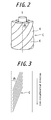
- a steel cord C comprised of each of the belts 2a, 2b, 2c preferably has a double twist structure in which a plurality of steel filaments are twisted to form a cable k and two to ten cables k are further twisted.
- the steel filament comprised of the cord C preferably has a diameter of 0.15 mm to 0.40 mm, more preferably 0.20 mm to 0.34 mm.
- the reference numeral 3 denotes a tread rubber layer. There are provided in the tread rubber layer 3 a plurality of groove portions 3a, which define land portions 3b.
- the pneumatic radial tire having the above-mentioned configuration can maintain separation performance in the edges of the belt, a hoop effect and a stiffness effect without degrading heat durability and improve cut penetration resistance and thus significantly improve durability of the belt.
- a cord of the first and second belts 2a preferably has an arrangement angle ⁇ 2 of not more than 10 degrees, more preferably within a range of 2 degrees and 8 degrees with respect to the circumferential direction of the tire.
- a sheath strand of the cord of the first and second belts 2a preferably has a twist angle ⁇ 1 with respect to an axis center L of the cord having a range of 3 degrees ⁇ ⁇ 1 ⁇ 13 degrees, more preferably a range of 5 degrees ⁇ ⁇ 1 ⁇ 10 degrees, and the relation of 2.0 > ⁇ 2 / ⁇ 1 > 0.4 is preferably satisfied.
- the cord section does not spread so as to assure separation resistance within the tire by setting 2.0 > ⁇ 2 / ⁇ 1 > 0.4.
- the diameter of the steel filament is preferably 0.15 mm to 0.40 mm, more preferably 0.20 mm to 0.34 mm.
- Pneumatic radial tires for mine vehicles, having the same structure except for a maximum width of a belt and a cord diameter of first and second belts as well as third and forth belts
- a size of 53/80R63 are produced, each of which comprises belt layers having different maximum widths.
- the tire is mounted on a regular rim (filling air pressure: 600kPa). Then, a running experiment is performed using each tire under the following condition to examine heat condition in the belt edges and cut penetration. The results are shown in Table 1.
- the width of the belt layers is shown in an index value with the width of the fifth and sixth belts being defined as 100 and the cord diameter of the belt layers is shown in an index value with the cord diameter of the third and forth belts being defined as 100.
- the heat condition in the belt edges is obtained by measuring the temperature in the edges of the second belt in the width direction of the tire and shown in an index value with the temperature of the reference tire being defined as 100 (the closer value to 100 means the better results).
- the cut penetration is estimated from a penetration examination with a model tire and shown in an index value with the reference tire being defined as 100 (the closer value to 100 means the better results).
- a tire of 53/80R63 is mounted on a rim of 36.00/5.0 with a load of 124.8 t and it runs in the speed of 10 km/h.
- the temperature of the edges of the second belt 2B is measured after 1 h after the run.
- Example tires 1 - 3 show smaller temperature increase due to heat generation than that of Comparative Example tires 1, 2 and show better results of cut penetration.
Landscapes
- Engineering & Computer Science (AREA)
- Mechanical Engineering (AREA)
- Tires In General (AREA)
Applications Claiming Priority (2)
| Application Number | Priority Date | Filing Date | Title |
|---|---|---|---|
| JP2006179581A JP4776455B2 (ja) | 2006-06-29 | 2006-06-29 | 重荷重用空気入りラジアルタイヤ |
| PCT/JP2007/063029 WO2008001862A1 (fr) | 2006-06-29 | 2007-06-28 | Pneumatique radial robuste tout usage |
Publications (3)
| Publication Number | Publication Date |
|---|---|
| EP2042348A1 true EP2042348A1 (fr) | 2009-04-01 |
| EP2042348A4 EP2042348A4 (fr) | 2012-01-25 |
| EP2042348B1 EP2042348B1 (fr) | 2013-06-05 |
Family
ID=38845626
Family Applications (1)
| Application Number | Title | Priority Date | Filing Date |
|---|---|---|---|
| EP07767822.5A Active EP2042348B1 (fr) | 2006-06-29 | 2007-06-28 | Pneumatique radial robuste tout usage |
Country Status (6)
| Country | Link |
|---|---|
| US (1) | US8261795B2 (fr) |
| EP (1) | EP2042348B1 (fr) |
| JP (1) | JP4776455B2 (fr) |
| CN (1) | CN101479116B (fr) |
| ES (1) | ES2425052T3 (fr) |
| WO (1) | WO2008001862A1 (fr) |
Families Citing this family (12)
| Publication number | Priority date | Publication date | Assignee | Title |
|---|---|---|---|---|
| US8903810B2 (en) | 2005-12-05 | 2014-12-02 | Collarity, Inc. | Techniques for ranking search results |
| US8429184B2 (en) | 2005-12-05 | 2013-04-23 | Collarity Inc. | Generation of refinement terms for search queries |
| JP5275656B2 (ja) * | 2008-03-25 | 2013-08-28 | 株式会社ブリヂストン | 空気入りタイヤ |
| JP2010254082A (ja) * | 2009-04-23 | 2010-11-11 | Bridgestone Corp | 重荷重用空気入りタイヤ |
| US8875038B2 (en) * | 2010-01-19 | 2014-10-28 | Collarity, Inc. | Anchoring for content synchronization |
| JP6058341B2 (ja) * | 2012-10-05 | 2017-01-11 | 株式会社ブリヂストン | 重荷重用空気入りタイヤ |
| JP6117556B2 (ja) * | 2013-01-23 | 2017-04-19 | 株式会社ブリヂストン | 建設車両用タイヤ |
| JP2016165924A (ja) * | 2015-03-09 | 2016-09-15 | 株式会社ブリヂストン | 重荷重用空気入りタイヤ |
| JP6555998B2 (ja) * | 2015-09-17 | 2019-08-07 | 株式会社ブリヂストン | 空気入りタイヤ |
| JP6694805B2 (ja) * | 2016-12-09 | 2020-05-20 | 株式会社ブリヂストン | 重荷重用タイヤ |
| JP2019035461A (ja) * | 2017-08-15 | 2019-03-07 | 株式会社ブリヂストン | 高圧ホース |
| CN108422811A (zh) * | 2018-04-16 | 2018-08-21 | 中策橡胶集团有限公司 | 一种扁平70以下系列的载重充气子午线轮胎 |
Family Cites Families (15)
| Publication number | Priority date | Publication date | Assignee | Title |
|---|---|---|---|---|
| DE3317744C2 (de) * | 1983-05-16 | 1985-08-22 | Akzo Gmbh, 5600 Wuppertal | Verstärkungscord mit Umschlingungsdraht |
| DE3481337D1 (de) | 1983-10-21 | 1990-03-15 | Vernon E Gleasman | Gleitfreies verbessertes differentialgetriebe. |
| JP3064108B2 (ja) * | 1992-07-24 | 2000-07-12 | 株式会社ブリヂストン | 重荷重用ラジアルタイヤ |
| JPH06173179A (ja) * | 1992-12-01 | 1994-06-21 | Bridgestone Corp | ゴム物品補強用スチールコード |
| JP3464501B2 (ja) * | 1993-07-06 | 2003-11-10 | 株式会社ブリヂストン | 重荷重用ラジアルタイヤ |
| FR2719257B1 (fr) * | 1994-04-28 | 1996-07-19 | Dunlop Sa | Pneumatique radial renforcé pour poids lourd. |
| US5661966A (en) * | 1996-06-27 | 1997-09-02 | Tokyo Rope Manufacturing Co. Ltd. | Steel cord for reinforcement of off-road tire, method of manufacturing the same, and off-road tire |
| JP2896976B2 (ja) * | 1995-06-27 | 1999-05-31 | 東京製綱株式会社 | 建設車両用スチールコード及び建設車両用タイヤ |
| JPH11170809A (ja) * | 1997-12-08 | 1999-06-29 | Bridgestone Corp | 重荷重用空気入りラジアル・タイヤ |
| JP4257713B2 (ja) * | 1998-04-10 | 2009-04-22 | 株式会社ブリヂストン | 重荷重用空気入りラジアルタイヤ |
| JP4097812B2 (ja) | 1998-11-13 | 2008-06-11 | 株式会社ブリヂストン | ゴム物品補強用スチールコードおよび空気入りタイヤ |
| JP2001301418A (ja) * | 2000-04-20 | 2001-10-31 | Bridgestone Corp | 空気入りタイヤ |
| JP4544782B2 (ja) | 2001-06-05 | 2010-09-15 | 株式会社ブリヂストン | ラジアルタイヤ |
| JP4373171B2 (ja) * | 2003-10-02 | 2009-11-25 | 株式会社ブリヂストン | 重荷重用空気入りラジアルタイヤ |
| JP4450686B2 (ja) * | 2004-07-06 | 2010-04-14 | 株式会社ブリヂストン | ゴム補強用スチールコードおよびタイヤ |
-
2006
- 2006-06-29 JP JP2006179581A patent/JP4776455B2/ja active Active
-
2007
- 2007-06-28 US US12/306,771 patent/US8261795B2/en not_active Expired - Fee Related
- 2007-06-28 CN CN2007800245492A patent/CN101479116B/zh not_active Expired - Fee Related
- 2007-06-28 EP EP07767822.5A patent/EP2042348B1/fr active Active
- 2007-06-28 WO PCT/JP2007/063029 patent/WO2008001862A1/fr not_active Ceased
- 2007-06-28 ES ES07767822T patent/ES2425052T3/es active Active
Also Published As
| Publication number | Publication date |
|---|---|
| EP2042348B1 (fr) | 2013-06-05 |
| CN101479116B (zh) | 2011-01-26 |
| US20090277556A1 (en) | 2009-11-12 |
| US8261795B2 (en) | 2012-09-11 |
| CN101479116A (zh) | 2009-07-08 |
| ES2425052T3 (es) | 2013-10-11 |
| WO2008001862A1 (fr) | 2008-01-03 |
| JP4776455B2 (ja) | 2011-09-21 |
| JP2008006969A (ja) | 2008-01-17 |
| EP2042348A4 (fr) | 2012-01-25 |
Similar Documents
| Publication | Publication Date | Title |
|---|---|---|
| EP2042348B1 (fr) | Pneumatique radial robuste tout usage | |
| EP2607104B1 (fr) | Pneu | |
| EP2123483B1 (fr) | Pneu | |
| EP1902867B1 (fr) | Pneu radial | |
| EP3305550A1 (fr) | Élément de renforcement pour pneumatique, et pneumatique mettant en uvre celui-ci | |
| EP1872972A2 (fr) | Pneumatique poids-lourds | |
| EP2106930A1 (fr) | Pneu à carcasse radiale | |
| EP2186652A1 (fr) | Pneu pour motocyclette pour déplacement en terrain accidenté | |
| EP3711978B1 (fr) | Pneumatique pour fonctionnement intensif | |
| EP2957435B1 (fr) | Pneu pour service lourd | |
| EP2583837A1 (fr) | Pneumatique à carcasse radiale pour automobiles | |
| EP3549786A1 (fr) | Composite caoutchouc-câble, élément de renfort pour pneus, et pneu l'utilisant | |
| EP3213929A1 (fr) | Pneumatique pour voitures de tourisme | |
| EP3381714B1 (fr) | Pneu de moto | |
| EP3305551A1 (fr) | Élément de renforcement pour pneumatique, et pneumatique mettant en uvre celui-ci | |
| EP3995322B1 (fr) | Pneu et couche de ceinture | |
| EP3181375B1 (fr) | Bandage pneumatique | |
| EP4134247B1 (fr) | Pneumatique | |
| EP3854608B1 (fr) | Câble composite et pneu l'utilisant | |
| EP3251875B1 (fr) | Pneumatique pour motocycle | |
| EP1676731B1 (fr) | Pneumatique radial | |
| EP2808178B1 (fr) | Élément de renforcement de pneumatique et pneumatique utilisant cet élément | |
| EP1905616A2 (fr) | Pneumatique radial | |
| CN101272922A (zh) | 充气子午线轮胎 | |
| EP2657046B1 (fr) | Pneu à carcasse radiale |
Legal Events
| Date | Code | Title | Description |
|---|---|---|---|
| PUAI | Public reference made under article 153(3) epc to a published international application that has entered the european phase |
Free format text: ORIGINAL CODE: 0009012 |
|
| 17P | Request for examination filed |
Effective date: 20081230 |
|
| AK | Designated contracting states |
Kind code of ref document: A1 Designated state(s): AT BE BG CH CY CZ DE DK EE ES FI FR GB GR HU IE IS IT LI LT LU LV MC MT NL PL PT RO SE SI SK TR |
|
| AX | Request for extension of the european patent |
Extension state: AL BA HR MK RS |
|
| DAX | Request for extension of the european patent (deleted) | ||
| RBV | Designated contracting states (corrected) |
Designated state(s): ES FR |
|
| REG | Reference to a national code |
Ref country code: DE Ref legal event code: 8566 |
|
| A4 | Supplementary search report drawn up and despatched |
Effective date: 20111228 |
|
| RIC1 | Information provided on ipc code assigned before grant |
Ipc: B60C 9/28 20060101ALI20111221BHEP Ipc: B60C 9/18 20060101AFI20111221BHEP Ipc: B60C 9/00 20060101ALI20111221BHEP Ipc: B60C 9/20 20060101ALI20111221BHEP |
|
| RIC1 | Information provided on ipc code assigned before grant |
Ipc: B60C 9/20 20060101ALI20120822BHEP Ipc: B60C 9/18 20060101AFI20120822BHEP Ipc: B60C 9/28 20060101ALI20120822BHEP Ipc: B60C 9/00 20060101ALI20120822BHEP |
|
| GRAP | Despatch of communication of intention to grant a patent |
Free format text: ORIGINAL CODE: EPIDOSNIGR1 |
|
| GRAS | Grant fee paid |
Free format text: ORIGINAL CODE: EPIDOSNIGR3 |
|
| GRAA | (expected) grant |
Free format text: ORIGINAL CODE: 0009210 |
|
| AK | Designated contracting states |
Kind code of ref document: B1 Designated state(s): ES FR |
|
| REG | Reference to a national code |
Ref country code: ES Ref legal event code: FG2A Ref document number: 2425052 Country of ref document: ES Kind code of ref document: T3 Effective date: 20131011 |
|
| PLBE | No opposition filed within time limit |
Free format text: ORIGINAL CODE: 0009261 |
|
| STAA | Information on the status of an ep patent application or granted ep patent |
Free format text: STATUS: NO OPPOSITION FILED WITHIN TIME LIMIT |
|
| 26N | No opposition filed |
Effective date: 20140306 |
|
| REG | Reference to a national code |
Ref country code: FR Ref legal event code: CA Effective date: 20140812 |
|
| REG | Reference to a national code |
Ref country code: FR Ref legal event code: PLFP Year of fee payment: 10 |
|
| REG | Reference to a national code |
Ref country code: FR Ref legal event code: PLFP Year of fee payment: 11 |
|
| REG | Reference to a national code |
Ref country code: FR Ref legal event code: PLFP Year of fee payment: 12 |
|
| PGFP | Annual fee paid to national office [announced via postgrant information from national office to epo] |
Ref country code: ES Payment date: 20220829 Year of fee payment: 16 |
|
| P01 | Opt-out of the competence of the unified patent court (upc) registered |
Effective date: 20230531 |
|
| REG | Reference to a national code |
Ref country code: ES Ref legal event code: FD2A Effective date: 20240802 |
|
| PG25 | Lapsed in a contracting state [announced via postgrant information from national office to epo] |
Ref country code: ES Free format text: LAPSE BECAUSE OF NON-PAYMENT OF DUE FEES Effective date: 20230629 |
|
| PG25 | Lapsed in a contracting state [announced via postgrant information from national office to epo] |
Ref country code: ES Free format text: LAPSE BECAUSE OF NON-PAYMENT OF DUE FEES Effective date: 20230629 |
|
| PGFP | Annual fee paid to national office [announced via postgrant information from national office to epo] |
Ref country code: FR Payment date: 20250620 Year of fee payment: 19 |