EP2042407A2 - Véhicule agricole avec son sytème de direction - Google Patents
Véhicule agricole avec son sytème de direction Download PDFInfo
- Publication number
- EP2042407A2 EP2042407A2 EP08162952A EP08162952A EP2042407A2 EP 2042407 A2 EP2042407 A2 EP 2042407A2 EP 08162952 A EP08162952 A EP 08162952A EP 08162952 A EP08162952 A EP 08162952A EP 2042407 A2 EP2042407 A2 EP 2042407A2
- Authority
- EP
- European Patent Office
- Prior art keywords
- steering
- vehicle
- axle
- angle
- steering angle
- Prior art date
- Legal status (The legal status is an assumption and is not a legal conclusion. Google has not performed a legal analysis and makes no representation as to the accuracy of the status listed.)
- Granted
Links
Images

Classifications
-
- B—PERFORMING OPERATIONS; TRANSPORTING
- B62—LAND VEHICLES FOR TRAVELLING OTHERWISE THAN ON RAILS
- B62D—MOTOR VEHICLES; TRAILERS
- B62D5/00—Power-assisted or power-driven steering
- B62D5/008—Changing the transfer ratio between the steering wheel and the steering gear by variable supply of energy, e.g. by using a superposition gear
-
- B—PERFORMING OPERATIONS; TRANSPORTING
- B60—VEHICLES IN GENERAL
- B60G—VEHICLE SUSPENSION ARRANGEMENTS
- B60G9/00—Resilient suspensions of a rigid axle or axle housing for two or more wheels
-
- B—PERFORMING OPERATIONS; TRANSPORTING
- B62—LAND VEHICLES FOR TRAVELLING OTHERWISE THAN ON RAILS
- B62D—MOTOR VEHICLES; TRAILERS
- B62D6/00—Arrangements for automatically controlling steering depending on driving conditions sensed and responded to, e.g. control circuits
- B62D6/002—Arrangements for automatically controlling steering depending on driving conditions sensed and responded to, e.g. control circuits computing target steering angles for front or rear wheels
-
- B—PERFORMING OPERATIONS; TRANSPORTING
- B60—VEHICLES IN GENERAL
- B60G—VEHICLE SUSPENSION ARRANGEMENTS
- B60G2200/00—Indexing codes relating to suspension types
- B60G2200/30—Rigid axle suspensions
- B60G2200/32—Rigid axle suspensions pivoted
- B60G2200/322—Rigid axle suspensions pivoted with a single pivot point and a straight axle
-
- B—PERFORMING OPERATIONS; TRANSPORTING
- B60—VEHICLES IN GENERAL
- B60G—VEHICLE SUSPENSION ARRANGEMENTS
- B60G2200/00—Indexing codes relating to suspension types
- B60G2200/40—Indexing codes relating to the wheels in the suspensions
- B60G2200/44—Indexing codes relating to the wheels in the suspensions steerable
-
- B—PERFORMING OPERATIONS; TRANSPORTING
- B60—VEHICLES IN GENERAL
- B60G—VEHICLE SUSPENSION ARRANGEMENTS
- B60G2300/00—Indexing codes relating to the type of vehicle
- B60G2300/08—Agricultural vehicles
- B60G2300/082—Tractors
Definitions
- the invention relates to an agricultural vehicle with a vehicle frame, at least one vehicle axle having at least one equipped with a wheel stub axle, wherein the at least one vehicle axle relative to the frame is suspended vertically movable and wheel steerable via a steering knuckle, an electronic control unit and a steering system generating a steering angle on the steering knuckle, the steering system comprising a first steering device which can be operated by an operator and generates a manipulated variable, and a second steering device, wherein the second steering device is operable by an actuator controllable by the electronic control unit, which generates a second manipulated variable, and wherein the manipulated variables of both steering devices are superimposable to a total manipulated variable generating the steering angle at the steering knuckle joint.
- the maximum steering angle or maximum steering angle is usually purely mechanically limited by (adjustable) rigid stops on the vehicle frame.
- the maximum steering angle or maximum steering angle must be set so that no contact between the vehicle body (frame, hood, etc.) and wheels occurs in any position from vehicle axle to vehicle frame, which could lead to damage to the components on the vehicle.
- electromechanical or electrohydraulic steering systems which generate the steering on the vehicle by superposition of the steering signal of a first steering device initiated by an operator with an additional control signal of a second steering device.
- an auxiliary power device is created by an overlay plate in the steering system, by which an auxiliary power to the driver independent correction of the steering torque is generated to protect the driver against unexpectedly occurring reaction torques.
- such a system is not suitable for limiting the steering angle on a vehicle axle.
- DE 196 01 826 A1 discloses a steering system for a motor vehicle having a coupled with a steering gear superposition gear.
- superimposition of a steering movement of a first steering device initiated by the driver with a movement of a second steering device initiated by an actuator takes place here in order to create a variable design of the mechanical transmission of the steering gear, which is designed to be constant.
- a limitation of the steering angle as described above can not be realized.
- the object underlying the invention is seen to provide an agricultural vehicle of the type mentioned, by which the aforementioned problems are overcome.
- an agricultural vehicle of the type mentioned above is provided with means for detecting the current steering angle and with means for detecting the current position of the at least one vehicle axle relative to the vehicle frame, and the control unit is designed such that by controlling the actuator limiting the steering angle in dependence from the current steering angle and from the current position of the at least one vehicle axle can be achieved.
- the position of the vehicle axle relative to the vehicle frame (swivel angle or swiveling angle, pendulum angle and / or travel) is determined online via suitable means.
- the maximum permitted steering angle is determined and the currently measured steering angle is corrected if necessary, if this exceeds the maximum permitted steering angle.
- the correction takes place by superposition of the manipulated variable initiated by the operator with the manipulated variable initiated by the actuator, so that the maximum steering angle or steering angle on the vehicle axle is actively limited in the end result as a function of the determined position of the vehicle axle.
- the operator driver of the vehicle
- the maximum permitted steering angle steering angle
- the actual steering angle (steering angle) is actively pursued the maximum permitted steering angle, ie it Correction of the steering angle by active return steering, if the current steering angle exceeds the maximum permitted steering angle. This is done as described above by active engagement of the actuator in the steering system.
- the current steering angle or steering angle is actively only reduced, that is, the actuator is activated only in case of exceeding the maximum permitted steering angle by the electronic control unit and corrects the current steering angle.
- the actuator is activated only in case of exceeding the maximum permitted steering angle by the electronic control unit and corrects the current steering angle.
- operator release eg, by an activation switch
- an activation device for example an activation switch, can generally be provided, by which only the above-described active correction of the steering angle is generally activated, so that the above-described processes must first be released by the operator.
- the vehicle axle is a pendulum axle with at least two with a Wheel-equipped stub axle formed, such that the means for detecting the current position of the vehicle axle determine or detect a pendulum angle relative to the vehicle frame.
- the pendulum axle can be designed both as a pendulum axle suspended centrally of the vehicle frame and as a pendulum axle (separate pivoting axle pair) suspended on both sides of the vehicle frame.
- a centrally suspended to the vehicle frame swing axle is rigid, with the axle ends extend from both sides of the vehicle frame to the wheels.
- Pendulum axles suspended on both sides of the vehicle frame are, in the actual sense, a pair of pivot axes, with one pivot axis extending on each side of the vehicle frame separated from the other to the respective wheel or a respective wheel suspension.
- the vehicle axle is designed as a sprung vehicle axle, wherein the means for detecting the current position of the vehicle axle capture a spring travel relative to the vehicle frame.
- the vehicle axle can be designed as a pendulum axle suspended centrally of the vehicle frame or as a separate pendulum axle suspended on both sides (pivot axle pair).
- the limitation of the steering angle can preferably be generated as a function of data stored in the control unit, wherein the data represent the maximum (permissible) steering angles (maximum (permissible) steering angles) and wherein the maximum steering angles are defined as a function of the position of the vehicle axle relative to the vehicle frame.
- the first and / or second steering device is designed as a mechanical or electromechanical, as electrical, as a hydraulic or electro-hydraulic or as a pneumatic or electropneumatic steering device.
- the superimposition of the manipulated variables of both steering devices preferably takes place by means of a superimposition gear, so that the current steering angle can be actively corrected in parallel with a manipulated variable (steering command) caused by the operator via the first steering device via the manipulated variable (steering angle correction command) caused by the second steering device.
- the means for detecting the current steering angle preferably include angle sensors which detect or signal the angle of rotation of a steering knuckle and / or the position of the axle pivot.
- angle sensors which detect or signal the angle of rotation of a steering knuckle and / or the position of the axle pivot.
- the position of the steering knuckle associated track rod can be determined.
- the means for detecting the current position of a vehicle axle preferably include angle sensors which detect or signal the pivot angle of a vehicle axle. Furthermore, it is also possible to provide different types of sensors at the same or different location or identical sensors at a different location, which detect the pivoting angle of the vehicle axle.
- the correction is effected by the second manipulated variable as a function of a driving speed of the vehicle, so that for example an active return (correction of the steering angle) takes place only at certain driving speeds and a maximum possible steering angle is released in certain speed ranges without correction.
- FIG. 1 shows an inventive agricultural vehicle 10 in the form of a tractor, which are also other agricultural vehicles, such. B. could be harvesters, loaders or self-propelled sprayers.
- the vehicle 10 has a vehicle axle 12 with wheels 16 which are steerably arranged on it via a steering knuckle 14.
- the vehicle axle 12 is designed as a pendulum axle and has a pendulum or pivot bearing 20 arranged centrally with respect to the vehicle frame 18.
- suspension cylinder 22 which represent a suspension of the vehicle axle formed as a swing axle 12.
- the vehicle axle 12 can thus move vertically in the direction of a wheel contact surface 24 (ground surface) relative to the vehicle frame 18 and at the same time pivot about a pivot axis parallel to a vehicle longitudinal axis 26 or move around it in a pendulum fashion.
- the ends of the vehicle axle 12 are connected via pivot axes 28 pivotally connected to wheel axles 30 on which the wheels 16 are suspended.
- the wheel axles 30 are fixedly connected to stub axles 32, such that pivoting of the wheel axles 30 and thus of the wheels 16 is triggered by moving or pivoting the stub axles 32 about the pivot axles 28.
- the free end of a respective stub axle 32 is in each case connected to one end of a tie rod 34, so that the stub axles 32 are connected to one another in an articulated manner via the tie rod 34 and form the above-mentioned stub axle steering 14.
- By laterally displacing the tie rod 34 a pivoting of the steering knuckle 32 and thus a corresponding steering movement or a corresponding steering angle is triggered.
- a position sensor 36 is arranged, which detects or detects the position of the tie rod 34 and a displacement of the tie rod 34 and thus constitutes a means for detecting or determining a current steering angle on the wheels 16.
- position sensors 38 are arranged, which determine the vertical movement of the vehicle axle 12 relative to the vehicle frame 18 or detect and thus reflect a suspension state (suspension position) of the vehicle axle.
- an angle sensor 40 is arranged on the vehicle axle 12 in the region of the pivot bearing 20, by which a pendulum position or a pendulum angle of the vehicle axle 12 is determined or detected relative to the vehicle frame 18.
- the position sensors 38 and the angle sensor 40 thereby represent means which are used for determining or detecting the current position of the vehicle axle 12 relative to the vehicle frame 18.
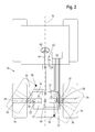
- the tie rod 34 is connected to a steering system 42, the structure of which is schematically illustrated in FIG FIG. 2 is shown.
- the steering system 42 includes a first steering device 44 and a second steering device 46.
- the first steering device 44 is operable by an operator via a steering wheel 48 of the vehicle 10 (or alternatively via other steering means, such as a steering lever or joystick), whereby a first manipulated variable is generated.
- the second steering device 46 is actuated by an actuator 50 which can be controlled by an electronic control unit 52 and by which a second manipulated variable is generated.
- the actuator 50 may be formed as an electric motor. Alternatively, another kind, for example, a hydraulically or pneumatically controlled motor can be provided.
- the steering system 42 includes a superposition gear 54, in which superimposed the first and second manipulated variable to a Bacstelliere.
- the total control variable determines the resulting steering angle of the steering knuckle 14, the total control variable being transmitted to the steering knuckle 14 via a steering gear 56 actuating the tie rod 34.
- the electronic control unit 52 is connected to the sensors 36, 38, 40 and generates as needed a correction signal or control signal for driving the actuator 50.
- data are stored, the corresponding maximum steering angles depending on a current steering angle and define a current position of the vehicle axle 12. Should the current steering angle, which is registered or detected online by the control unit 52, exceed the maximum steering angle determined in dependence on the current position of the vehicle axle 12 for a specific operating situation, then the electronic control unit 52 generates a corresponding correction signal (control signal) for the driver Steering angle, by which the actuator 50 is activated and in turn generates a corresponding second manipulated variable, which in turn is superimposed on the first manipulated variable.
- the electronic control unit 52 thus corrects the current steering angle as soon as the maximum steering angle is reached or exceeded for a specific operating situation with respect to the position of the vehicle axle 12, the correction signal being based on the sensor signals of the vehicle 10 and the steering system 42 arranged position and Angle sensors 36, 38, 40 is generated.
- the data stored in the electronic control unit 52 with respect to the maximum steering angles are to be determined individually depending on the geometric dimensions of the vehicle 10 and the wheels 16 to be steered and fed into the electronic control unit 52.
- Collision points 58 shown for a particular position of the vehicle axle 16 wherein the maximum steering angle (the maximum permitted steering angle without a collision of the wheels 16 enters the vehicle body) always changes depending on the position or suspension position of the vehicle axle 12.
Landscapes
- Engineering & Computer Science (AREA)
- Mechanical Engineering (AREA)
- Chemical & Material Sciences (AREA)
- Combustion & Propulsion (AREA)
- Transportation (AREA)
- Physics & Mathematics (AREA)
- Mathematical Physics (AREA)
- Steering Control In Accordance With Driving Conditions (AREA)
- Vehicle Body Suspensions (AREA)
Applications Claiming Priority (1)
| Application Number | Priority Date | Filing Date | Title |
|---|---|---|---|
| DE102007045781A DE102007045781A1 (de) | 2007-09-25 | 2007-09-25 | Landwirtschaftliches Fahrzeug |
Publications (3)
| Publication Number | Publication Date |
|---|---|
| EP2042407A2 true EP2042407A2 (fr) | 2009-04-01 |
| EP2042407A3 EP2042407A3 (fr) | 2012-10-03 |
| EP2042407B1 EP2042407B1 (fr) | 2013-11-13 |
Family
ID=40119414
Family Applications (1)
| Application Number | Title | Priority Date | Filing Date |
|---|---|---|---|
| EP20080162952 Active EP2042407B1 (fr) | 2007-09-25 | 2008-08-26 | Véhicule agricole avec son sytème de direction |
Country Status (2)
| Country | Link |
|---|---|
| EP (1) | EP2042407B1 (fr) |
| DE (1) | DE102007045781A1 (fr) |
Cited By (5)
| Publication number | Priority date | Publication date | Assignee | Title |
|---|---|---|---|---|
| CN104724170A (zh) * | 2013-12-19 | 2015-06-24 | 凯斯纽荷兰(中国)管理有限公司 | 用于主动地确定作业车辆的转向限位角的系统和方法 |
| US10577013B2 (en) | 2016-12-20 | 2020-03-03 | Deere & Company | Steering assistance system for an agricultural vehicle |
| EP3718861A1 (fr) * | 2019-04-02 | 2020-10-07 | Deere & Company | Dispositif de direction pour un véhicule agricole |
| EP3798028A1 (fr) | 2019-09-30 | 2021-03-31 | CLAAS Tractor S.A.S. | Machine de travail agricole et procédé de direction d'une machine agricole |
| CN118850074A (zh) * | 2024-07-03 | 2024-10-29 | 中国重汽集团济南动力有限公司 | 一种用于齿轮齿条转向器的转向参数优化方法、装置、设备及介质 |
Families Citing this family (2)
| Publication number | Priority date | Publication date | Assignee | Title |
|---|---|---|---|---|
| DE102015120480A1 (de) | 2015-11-26 | 2017-06-01 | Amazonen-Werke H. Dreyer Gmbh & Co. Kg | Fahrzeug zur Pflege von Grünflächen und Verfahren zur Lenkung eines solchen Fahrzeugs |
| DE102019125792B4 (de) | 2019-09-25 | 2021-12-16 | Crown Equipment Corp. | Elektrisch betriebenes Lenkungssystem für ein Fahrzeug |
Citations (3)
| Publication number | Priority date | Publication date | Assignee | Title |
|---|---|---|---|---|
| DE19601826A1 (de) | 1996-01-19 | 1997-07-24 | Bosch Gmbh Robert | Lenksystem für ein Kraftfahrzeug |
| DE102004027586A1 (de) | 2004-06-05 | 2005-12-22 | Daimlerchrysler Ag | Verfahren zum Betrieb eines Hilfskraftlenksystems und Hilfskraftlenksystem |
| DE102005038390A1 (de) | 2004-12-07 | 2006-06-14 | Volkswagen Ag | Lenkung eines Fahrzeugs |
Family Cites Families (4)
| Publication number | Priority date | Publication date | Assignee | Title |
|---|---|---|---|---|
| KR100316918B1 (ko) * | 1999-07-14 | 2001-12-22 | 이계안 | 자동차의 최소 회전반경 조절시스템 |
| DE10221721B4 (de) * | 2002-05-16 | 2011-02-17 | Bayerische Motoren Werke Aktiengesellschaft | Kraftfahrzeug mit einem Lenksystem sowie einem Anschlag zum Begrenzen des maximalen Einschlagwinkels |
| DE10244067A1 (de) * | 2002-09-06 | 2004-04-01 | Volkswagen Ag | Vorrichtung und Verfahren zur Lenkunterstützung für Fahrzeuge mit elektromechanischer Lenkung |
| DE102005061522A1 (de) * | 2005-12-22 | 2007-07-05 | Zf Lenksysteme Gmbh | Lenkbare Achse |
-
2007
- 2007-09-25 DE DE102007045781A patent/DE102007045781A1/de not_active Withdrawn
-
2008
- 2008-08-26 EP EP20080162952 patent/EP2042407B1/fr active Active
Patent Citations (3)
| Publication number | Priority date | Publication date | Assignee | Title |
|---|---|---|---|---|
| DE19601826A1 (de) | 1996-01-19 | 1997-07-24 | Bosch Gmbh Robert | Lenksystem für ein Kraftfahrzeug |
| DE102004027586A1 (de) | 2004-06-05 | 2005-12-22 | Daimlerchrysler Ag | Verfahren zum Betrieb eines Hilfskraftlenksystems und Hilfskraftlenksystem |
| DE102005038390A1 (de) | 2004-12-07 | 2006-06-14 | Volkswagen Ag | Lenkung eines Fahrzeugs |
Cited By (7)
| Publication number | Priority date | Publication date | Assignee | Title |
|---|---|---|---|---|
| CN104724170A (zh) * | 2013-12-19 | 2015-06-24 | 凯斯纽荷兰(中国)管理有限公司 | 用于主动地确定作业车辆的转向限位角的系统和方法 |
| EP2886419A3 (fr) * | 2013-12-19 | 2016-04-06 | CNH Industrial Italia S.p.A. | Système et procédé pour déterminer activement un angle de butée de direction pour un véhicule de travail |
| US10577013B2 (en) | 2016-12-20 | 2020-03-03 | Deere & Company | Steering assistance system for an agricultural vehicle |
| EP3718861A1 (fr) * | 2019-04-02 | 2020-10-07 | Deere & Company | Dispositif de direction pour un véhicule agricole |
| US11807295B2 (en) * | 2019-04-02 | 2023-11-07 | Deere & Company | Steering apparatus for an agricultural vehicle |
| EP3798028A1 (fr) | 2019-09-30 | 2021-03-31 | CLAAS Tractor S.A.S. | Machine de travail agricole et procédé de direction d'une machine agricole |
| CN118850074A (zh) * | 2024-07-03 | 2024-10-29 | 中国重汽集团济南动力有限公司 | 一种用于齿轮齿条转向器的转向参数优化方法、装置、设备及介质 |
Also Published As
| Publication number | Publication date |
|---|---|
| EP2042407B1 (fr) | 2013-11-13 |
| EP2042407A3 (fr) | 2012-10-03 |
| DE102007045781A1 (de) | 2009-04-09 |
Similar Documents
| Publication | Publication Date | Title |
|---|---|---|
| EP3022107B1 (fr) | Procédé permettant de faire fonctionner la direction d'un véhicule automobile | |
| DE10040870B4 (de) | Lenksystem für ein Fahrzeug | |
| EP0970875B1 (fr) | Système de direction pour véhicules | |
| EP1849682B1 (fr) | Procédé destiné au réglage de la direction | |
| EP2042407B1 (fr) | Véhicule agricole avec son sytème de direction | |
| EP0975507B1 (fr) | Servo-direction a servo-assistance hydraulique | |
| EP1091868B1 (fr) | Direction assistee hydrauliquement | |
| WO2017198565A1 (fr) | Système à commande électrique « steer-by-wire », véhicule automobile et procédé de fonctionnement d'un système à commande électrique « steer-by-wire » | |
| EP3216677B1 (fr) | Module de contre-rail pour véhicules automobiles comprenant une direction individuelle des roues | |
| EP3428041A1 (fr) | Colonne de direction multifonctionnelle, véhicule automobile et procédé de fonctionnement d'un véhicule automobile | |
| WO2015055363A1 (fr) | Dispositif d'angle de braquage pour un véhicule automobile | |
| WO2002060741A1 (fr) | Systeme de direction pour vehicules non guides | |
| DE10007658A1 (de) | Regelbares Aufhängungssystem für ein aktives Fahrzeugfahrwerk | |
| EP3343311B1 (fr) | Levier de commande pourvu d'unité de rétroaction active | |
| EP2935087B1 (fr) | Procédé de direction et chariot de manutention | |
| EP3487804A1 (fr) | Procédé de fonctionnement et chariot de manutention | |
| EP2679470B1 (fr) | Dispositif destiné à diriger un elément agricole | |
| DE19908323B4 (de) | Gelenkte Fahrzeugachse | |
| DE102022104584A1 (de) | Lenksystem und lenkbare Achse für ein Kraftfahrzeug | |
| DE102020208261B4 (de) | Endanschlags-Rückstellfunktion für eine Fahrzeuglenkung | |
| WO2008071496A1 (fr) | Système de direction de véhicule | |
| DE10008984A1 (de) | Lenksystem für ein Flurförderzeug | |
| DE202004007061U1 (de) | Telelader, insbesondere Reachstacker | |
| EP4134294B1 (fr) | Système de direction pour un véhicule agricole | |
| DE10253468A1 (de) | Servolenkung mit Rangier-Betriebsweise |
Legal Events
| Date | Code | Title | Description |
|---|---|---|---|
| PUAI | Public reference made under article 153(3) epc to a published international application that has entered the european phase |
Free format text: ORIGINAL CODE: 0009012 |
|
| AK | Designated contracting states |
Kind code of ref document: A2 Designated state(s): AT BE BG CH CY CZ DE DK EE ES FI FR GB GR HR HU IE IS IT LI LT LU LV MC MT NL NO PL PT RO SE SI SK TR |
|
| AX | Request for extension of the european patent |
Extension state: AL BA MK RS |
|
| PUAL | Search report despatched |
Free format text: ORIGINAL CODE: 0009013 |
|
| AK | Designated contracting states |
Kind code of ref document: A3 Designated state(s): AT BE BG CH CY CZ DE DK EE ES FI FR GB GR HR HU IE IS IT LI LT LU LV MC MT NL NO PL PT RO SE SI SK TR |
|
| AX | Request for extension of the european patent |
Extension state: AL BA MK RS |
|
| RIC1 | Information provided on ipc code assigned before grant |
Ipc: B60G 9/00 20060101ALI20120830BHEP Ipc: B62D 5/04 20060101ALI20120830BHEP Ipc: B62D 5/00 20060101ALI20120830BHEP Ipc: B62D 6/00 20060101AFI20120830BHEP |
|
| 17P | Request for examination filed |
Effective date: 20130403 |
|
| GRAP | Despatch of communication of intention to grant a patent |
Free format text: ORIGINAL CODE: EPIDOSNIGR1 |
|
| AKX | Designation fees paid |
Designated state(s): AT BE BG CH CY CZ DE DK EE ES FI FR GB GR HR HU IE IS IT LI LT LU LV MC MT NL NO PL PT RO SE SI SK TR |
|
| INTG | Intention to grant announced |
Effective date: 20130611 |
|
| GRAS | Grant fee paid |
Free format text: ORIGINAL CODE: EPIDOSNIGR3 |
|
| GRAA | (expected) grant |
Free format text: ORIGINAL CODE: 0009210 |
|
| AK | Designated contracting states |
Kind code of ref document: B1 Designated state(s): AT BE BG CH CY CZ DE DK EE ES FI FR GB GR HR HU IE IS IT LI LT LU LV MC MT NL NO PL PT RO SE SI SK TR |
|
| REG | Reference to a national code |
Ref country code: GB Ref legal event code: FG4D Free format text: NOT ENGLISH |
|
| REG | Reference to a national code |
Ref country code: CH Ref legal event code: EP |
|
| REG | Reference to a national code |
Ref country code: AT Ref legal event code: REF Ref document number: 640443 Country of ref document: AT Kind code of ref document: T Effective date: 20131215 |
|
| REG | Reference to a national code |
Ref country code: IE Ref legal event code: FG4D Free format text: LANGUAGE OF EP DOCUMENT: GERMAN |
|
| REG | Reference to a national code |
Ref country code: DE Ref legal event code: R096 Ref document number: 502008010946 Country of ref document: DE Effective date: 20140109 |
|
| REG | Reference to a national code |
Ref country code: NL Ref legal event code: VDEP Effective date: 20131113 |
|
| REG | Reference to a national code |
Ref country code: LT Ref legal event code: MG4D |
|
| PG25 | Lapsed in a contracting state [announced via postgrant information from national office to epo] |
Ref country code: LT Free format text: LAPSE BECAUSE OF FAILURE TO SUBMIT A TRANSLATION OF THE DESCRIPTION OR TO PAY THE FEE WITHIN THE PRESCRIBED TIME-LIMIT Effective date: 20131113 Ref country code: NO Free format text: LAPSE BECAUSE OF FAILURE TO SUBMIT A TRANSLATION OF THE DESCRIPTION OR TO PAY THE FEE WITHIN THE PRESCRIBED TIME-LIMIT Effective date: 20140213 Ref country code: NL Free format text: LAPSE BECAUSE OF FAILURE TO SUBMIT A TRANSLATION OF THE DESCRIPTION OR TO PAY THE FEE WITHIN THE PRESCRIBED TIME-LIMIT Effective date: 20131113 Ref country code: IS Free format text: LAPSE BECAUSE OF FAILURE TO SUBMIT A TRANSLATION OF THE DESCRIPTION OR TO PAY THE FEE WITHIN THE PRESCRIBED TIME-LIMIT Effective date: 20140313 Ref country code: SE Free format text: LAPSE BECAUSE OF FAILURE TO SUBMIT A TRANSLATION OF THE DESCRIPTION OR TO PAY THE FEE WITHIN THE PRESCRIBED TIME-LIMIT Effective date: 20131113 Ref country code: HR Free format text: LAPSE BECAUSE OF FAILURE TO SUBMIT A TRANSLATION OF THE DESCRIPTION OR TO PAY THE FEE WITHIN THE PRESCRIBED TIME-LIMIT Effective date: 20131113 |
|
| PG25 | Lapsed in a contracting state [announced via postgrant information from national office to epo] |
Ref country code: LV Free format text: LAPSE BECAUSE OF FAILURE TO SUBMIT A TRANSLATION OF THE DESCRIPTION OR TO PAY THE FEE WITHIN THE PRESCRIBED TIME-LIMIT Effective date: 20131113 Ref country code: ES Free format text: LAPSE BECAUSE OF FAILURE TO SUBMIT A TRANSLATION OF THE DESCRIPTION OR TO PAY THE FEE WITHIN THE PRESCRIBED TIME-LIMIT Effective date: 20131113 Ref country code: CY Free format text: LAPSE BECAUSE OF FAILURE TO SUBMIT A TRANSLATION OF THE DESCRIPTION OR TO PAY THE FEE WITHIN THE PRESCRIBED TIME-LIMIT Effective date: 20131113 |
|
| PG25 | Lapsed in a contracting state [announced via postgrant information from national office to epo] |
Ref country code: PT Free format text: LAPSE BECAUSE OF FAILURE TO SUBMIT A TRANSLATION OF THE DESCRIPTION OR TO PAY THE FEE WITHIN THE PRESCRIBED TIME-LIMIT Effective date: 20140313 |
|
| PG25 | Lapsed in a contracting state [announced via postgrant information from national office to epo] |
Ref country code: EE Free format text: LAPSE BECAUSE OF FAILURE TO SUBMIT A TRANSLATION OF THE DESCRIPTION OR TO PAY THE FEE WITHIN THE PRESCRIBED TIME-LIMIT Effective date: 20131113 |
|
| REG | Reference to a national code |
Ref country code: DE Ref legal event code: R097 Ref document number: 502008010946 Country of ref document: DE |
|
| PG25 | Lapsed in a contracting state [announced via postgrant information from national office to epo] |
Ref country code: SK Free format text: LAPSE BECAUSE OF FAILURE TO SUBMIT A TRANSLATION OF THE DESCRIPTION OR TO PAY THE FEE WITHIN THE PRESCRIBED TIME-LIMIT Effective date: 20131113 Ref country code: RO Free format text: LAPSE BECAUSE OF FAILURE TO SUBMIT A TRANSLATION OF THE DESCRIPTION OR TO PAY THE FEE WITHIN THE PRESCRIBED TIME-LIMIT Effective date: 20131113 Ref country code: PL Free format text: LAPSE BECAUSE OF FAILURE TO SUBMIT A TRANSLATION OF THE DESCRIPTION OR TO PAY THE FEE WITHIN THE PRESCRIBED TIME-LIMIT Effective date: 20131113 Ref country code: CZ Free format text: LAPSE BECAUSE OF FAILURE TO SUBMIT A TRANSLATION OF THE DESCRIPTION OR TO PAY THE FEE WITHIN THE PRESCRIBED TIME-LIMIT Effective date: 20131113 |
|
| PLBE | No opposition filed within time limit |
Free format text: ORIGINAL CODE: 0009261 |
|
| STAA | Information on the status of an ep patent application or granted ep patent |
Free format text: STATUS: NO OPPOSITION FILED WITHIN TIME LIMIT |
|
| PG25 | Lapsed in a contracting state [announced via postgrant information from national office to epo] |
Ref country code: DK Free format text: LAPSE BECAUSE OF FAILURE TO SUBMIT A TRANSLATION OF THE DESCRIPTION OR TO PAY THE FEE WITHIN THE PRESCRIBED TIME-LIMIT Effective date: 20131113 |
|
| 26N | No opposition filed |
Effective date: 20140814 |
|
| REG | Reference to a national code |
Ref country code: DE Ref legal event code: R097 Ref document number: 502008010946 Country of ref document: DE Effective date: 20140814 |
|
| PG25 | Lapsed in a contracting state [announced via postgrant information from national office to epo] |
Ref country code: SI Free format text: LAPSE BECAUSE OF FAILURE TO SUBMIT A TRANSLATION OF THE DESCRIPTION OR TO PAY THE FEE WITHIN THE PRESCRIBED TIME-LIMIT Effective date: 20131113 |
|
| PG25 | Lapsed in a contracting state [announced via postgrant information from national office to epo] |
Ref country code: LU Free format text: LAPSE BECAUSE OF FAILURE TO SUBMIT A TRANSLATION OF THE DESCRIPTION OR TO PAY THE FEE WITHIN THE PRESCRIBED TIME-LIMIT Effective date: 20140826 Ref country code: MC Free format text: LAPSE BECAUSE OF FAILURE TO SUBMIT A TRANSLATION OF THE DESCRIPTION OR TO PAY THE FEE WITHIN THE PRESCRIBED TIME-LIMIT Effective date: 20131113 |
|
| REG | Reference to a national code |
Ref country code: CH Ref legal event code: PL |
|
| PG25 | Lapsed in a contracting state [announced via postgrant information from national office to epo] |
Ref country code: IT Free format text: LAPSE BECAUSE OF FAILURE TO SUBMIT A TRANSLATION OF THE DESCRIPTION OR TO PAY THE FEE WITHIN THE PRESCRIBED TIME-LIMIT Effective date: 20131113 Ref country code: CH Free format text: LAPSE BECAUSE OF NON-PAYMENT OF DUE FEES Effective date: 20140831 Ref country code: BE Free format text: LAPSE BECAUSE OF NON-PAYMENT OF DUE FEES Effective date: 20140831 Ref country code: LI Free format text: LAPSE BECAUSE OF NON-PAYMENT OF DUE FEES Effective date: 20140831 |
|
| REG | Reference to a national code |
Ref country code: IE Ref legal event code: MM4A |
|
| PG25 | Lapsed in a contracting state [announced via postgrant information from national office to epo] |
Ref country code: IE Free format text: LAPSE BECAUSE OF NON-PAYMENT OF DUE FEES Effective date: 20140826 |
|
| REG | Reference to a national code |
Ref country code: AT Ref legal event code: MM01 Ref document number: 640443 Country of ref document: AT Kind code of ref document: T Effective date: 20140826 |
|
| PG25 | Lapsed in a contracting state [announced via postgrant information from national office to epo] |
Ref country code: AT Free format text: LAPSE BECAUSE OF NON-PAYMENT OF DUE FEES Effective date: 20140826 |
|
| PG25 | Lapsed in a contracting state [announced via postgrant information from national office to epo] |
Ref country code: BG Free format text: LAPSE BECAUSE OF FAILURE TO SUBMIT A TRANSLATION OF THE DESCRIPTION OR TO PAY THE FEE WITHIN THE PRESCRIBED TIME-LIMIT Effective date: 20131113 |
|
| PG25 | Lapsed in a contracting state [announced via postgrant information from national office to epo] |
Ref country code: GR Free format text: LAPSE BECAUSE OF FAILURE TO SUBMIT A TRANSLATION OF THE DESCRIPTION OR TO PAY THE FEE WITHIN THE PRESCRIBED TIME-LIMIT Effective date: 20140214 Ref country code: MT Free format text: LAPSE BECAUSE OF FAILURE TO SUBMIT A TRANSLATION OF THE DESCRIPTION OR TO PAY THE FEE WITHIN THE PRESCRIBED TIME-LIMIT Effective date: 20131113 |
|
| PG25 | Lapsed in a contracting state [announced via postgrant information from national office to epo] |
Ref country code: TR Free format text: LAPSE BECAUSE OF FAILURE TO SUBMIT A TRANSLATION OF THE DESCRIPTION OR TO PAY THE FEE WITHIN THE PRESCRIBED TIME-LIMIT Effective date: 20131113 Ref country code: HU Free format text: LAPSE BECAUSE OF FAILURE TO SUBMIT A TRANSLATION OF THE DESCRIPTION OR TO PAY THE FEE WITHIN THE PRESCRIBED TIME-LIMIT; INVALID AB INITIO Effective date: 20080826 |
|
| REG | Reference to a national code |
Ref country code: FR Ref legal event code: PLFP Year of fee payment: 9 |
|
| REG | Reference to a national code |
Ref country code: FR Ref legal event code: PLFP Year of fee payment: 10 |
|
| REG | Reference to a national code |
Ref country code: FR Ref legal event code: PLFP Year of fee payment: 11 |
|
| PGFP | Annual fee paid to national office [announced via postgrant information from national office to epo] |
Ref country code: FI Payment date: 20250825 Year of fee payment: 18 |
|
| PGFP | Annual fee paid to national office [announced via postgrant information from national office to epo] |
Ref country code: DE Payment date: 20250721 Year of fee payment: 18 |
|
| PGFP | Annual fee paid to national office [announced via postgrant information from national office to epo] |
Ref country code: GB Payment date: 20250827 Year of fee payment: 18 |
|
| PGFP | Annual fee paid to national office [announced via postgrant information from national office to epo] |
Ref country code: FR Payment date: 20250825 Year of fee payment: 18 |