EP2042423A1 - Support de levier de vitesse frontal d'une bicyclette et levier de vitesse frontal de bicyclette comportant un tel support - Google Patents
Support de levier de vitesse frontal d'une bicyclette et levier de vitesse frontal de bicyclette comportant un tel support Download PDFInfo
- Publication number
- EP2042423A1 EP2042423A1 EP08006142A EP08006142A EP2042423A1 EP 2042423 A1 EP2042423 A1 EP 2042423A1 EP 08006142 A EP08006142 A EP 08006142A EP 08006142 A EP08006142 A EP 08006142A EP 2042423 A1 EP2042423 A1 EP 2042423A1
- Authority
- EP
- European Patent Office
- Prior art keywords
- support
- coupling portion
- anchoring portion
- bicycle
- anchoring
- Prior art date
- Legal status (The legal status is an assumption and is not a legal conclusion. Google has not performed a legal analysis and makes no representation as to the accuracy of the status listed.)
- Withdrawn
Links
- 238000004873 anchoring Methods 0.000 claims abstract description 95
- 238000010168 coupling process Methods 0.000 claims abstract description 90
- 230000008878 coupling Effects 0.000 claims abstract description 89
- 238000005859 coupling reaction Methods 0.000 claims abstract description 89
- 239000000463 material Substances 0.000 claims abstract description 23
- 238000000034 method Methods 0.000 claims description 15
- 238000004519 manufacturing process Methods 0.000 claims description 10
- 239000002131 composite material Substances 0.000 claims description 9
- 238000000465 moulding Methods 0.000 claims description 9
- 238000004026 adhesive bonding Methods 0.000 claims description 8
- 239000011208 reinforced composite material Substances 0.000 claims description 4
- 239000007769 metal material Substances 0.000 claims description 3
- 230000008901 benefit Effects 0.000 description 7
- 230000005540 biological transmission Effects 0.000 description 3
- 230000033001 locomotion Effects 0.000 description 3
- 230000008569 process Effects 0.000 description 3
- 229910000838 Al alloy Inorganic materials 0.000 description 2
- OKTJSMMVPCPJKN-UHFFFAOYSA-N Carbon Chemical compound [C] OKTJSMMVPCPJKN-UHFFFAOYSA-N 0.000 description 2
- 229910052799 carbon Inorganic materials 0.000 description 2
- 239000008187 granular material Substances 0.000 description 2
- 238000001746 injection moulding Methods 0.000 description 2
- 238000003780 insertion Methods 0.000 description 2
- 230000037431 insertion Effects 0.000 description 2
- 239000011159 matrix material Substances 0.000 description 2
- 229910052751 metal Inorganic materials 0.000 description 2
- 239000002184 metal Substances 0.000 description 2
- 229920000642 polymer Polymers 0.000 description 2
- 239000000843 powder Substances 0.000 description 2
- ZOXJGFHDIHLPTG-UHFFFAOYSA-N Boron Chemical compound [B] ZOXJGFHDIHLPTG-UHFFFAOYSA-N 0.000 description 1
- FYYHWMGAXLPEAU-UHFFFAOYSA-N Magnesium Chemical compound [Mg] FYYHWMGAXLPEAU-UHFFFAOYSA-N 0.000 description 1
- 238000009825 accumulation Methods 0.000 description 1
- 229920003235 aromatic polyamide Polymers 0.000 description 1
- 230000002457 bidirectional effect Effects 0.000 description 1
- 229910052796 boron Inorganic materials 0.000 description 1
- 239000000919 ceramic Substances 0.000 description 1
- 238000006243 chemical reaction Methods 0.000 description 1
- 238000004891 communication Methods 0.000 description 1
- 238000001816 cooling Methods 0.000 description 1
- 239000003822 epoxy resin Substances 0.000 description 1
- 230000002349 favourable effect Effects 0.000 description 1
- 239000000835 fiber Substances 0.000 description 1
- 239000000945 filler Substances 0.000 description 1
- 239000003365 glass fiber Substances 0.000 description 1
- 239000003292 glue Substances 0.000 description 1
- 230000002452 interceptive effect Effects 0.000 description 1
- 229910052749 magnesium Inorganic materials 0.000 description 1
- 239000011777 magnesium Substances 0.000 description 1
- 238000012986 modification Methods 0.000 description 1
- 230000004048 modification Effects 0.000 description 1
- 230000003387 muscular Effects 0.000 description 1
- 239000004033 plastic Substances 0.000 description 1
- 229920000647 polyepoxide Polymers 0.000 description 1
- 238000012545 processing Methods 0.000 description 1
- 230000001141 propulsive effect Effects 0.000 description 1
- 239000012815 thermoplastic material Substances 0.000 description 1
- 229920001187 thermosetting polymer Polymers 0.000 description 1
- 230000007704 transition Effects 0.000 description 1
Images


Classifications
-
- B—PERFORMING OPERATIONS; TRANSPORTING
- B62—LAND VEHICLES FOR TRAVELLING OTHERWISE THAN ON RAILS
- B62M—RIDER PROPULSION OF WHEELED VEHICLES OR SLEDGES; POWERED PROPULSION OF SLEDGES OR SINGLE-TRACK CYCLES; TRANSMISSIONS SPECIALLY ADAPTED FOR SUCH VEHICLES
- B62M9/00—Transmissions characterised by use of an endless chain, belt, or the like
- B62M9/04—Transmissions characterised by use of an endless chain, belt, or the like of changeable ratio
- B62M9/06—Transmissions characterised by use of an endless chain, belt, or the like of changeable ratio using a single chain, belt, or the like
- B62M9/10—Transmissions characterised by use of an endless chain, belt, or the like of changeable ratio using a single chain, belt, or the like involving different-sized wheels, e.g. rear sprocket chain wheels selectively engaged by the chain, belt, or the like
- B62M9/12—Transmissions characterised by use of an endless chain, belt, or the like of changeable ratio using a single chain, belt, or the like involving different-sized wheels, e.g. rear sprocket chain wheels selectively engaged by the chain, belt, or the like the chain, belt, or the like being laterally shiftable, e.g. using a rear derailleur
- B62M9/131—Front derailleurs
- B62M9/135—Mounting the derailleur on the frame
-
- Y—GENERAL TAGGING OF NEW TECHNOLOGICAL DEVELOPMENTS; GENERAL TAGGING OF CROSS-SECTIONAL TECHNOLOGIES SPANNING OVER SEVERAL SECTIONS OF THE IPC; TECHNICAL SUBJECTS COVERED BY FORMER USPC CROSS-REFERENCE ART COLLECTIONS [XRACs] AND DIGESTS
- Y10—TECHNICAL SUBJECTS COVERED BY FORMER USPC
- Y10T—TECHNICAL SUBJECTS COVERED BY FORMER US CLASSIFICATION
- Y10T29/00—Metal working
- Y10T29/49—Method of mechanical manufacture
- Y10T29/49462—Gear making
- Y10T29/49464—Assembling of gear into force transmitting device
-
- Y—GENERAL TAGGING OF NEW TECHNOLOGICAL DEVELOPMENTS; GENERAL TAGGING OF CROSS-SECTIONAL TECHNOLOGIES SPANNING OVER SEVERAL SECTIONS OF THE IPC; TECHNICAL SUBJECTS COVERED BY FORMER USPC CROSS-REFERENCE ART COLLECTIONS [XRACs] AND DIGESTS
- Y10—TECHNICAL SUBJECTS COVERED BY FORMER USPC
- Y10T—TECHNICAL SUBJECTS COVERED BY FORMER US CLASSIFICATION
- Y10T74/00—Machine element or mechanism
- Y10T74/20—Control lever and linkage systems
- Y10T74/20207—Multiple controlling elements for single controlled element
Definitions
- the present invention relates to a support for a bicycle front gearshift.
- the invention also relates to a bicycle front gearshift comprising such a support and a bicycle comprising the aforementioned front gearshift.
- a bicycle front gearshift comprising such a support and a bicycle comprising the aforementioned front gearshift.
- the aforementioned bicycle is a racing bicycle.
- the present invention relates to a method for manufacturing a support for a bicycle front gearshift.
- the bicycle is a mechanical vehicle moved by muscular driving force that is transmitted to the rear "driving" wheel through a motion transmission system.
- the motion transmission system comprises a pair of crank arms, on which the cyclist exerts a propulsive thrust, one or more driving toothed wheels, made to rotate by direct coupling with the crank arms, and one or more driven toothed wheels or “sprockets”, made to rotate by the driving toothed wheels through a chain, said sprockets being coupled with the hub of the rear wheel.
- racing bicycles comprise a plurality of sprockets of various diameters and a plurality of driving toothed wheels, also of various diameters.
- the chain simultaneously engages a driving toothed wheel and a sprocket and is selectively movable over them through a gearshift device, so as to obtain the combination of driving toothed wheel and sprocket that offers the most favourable transmission ratio for the conditions of the route.
- the bicycle typically comprises a front gearshift, which moves the chain from one driving toothed wheel to another, and a rear gearshift, which moves the chain from one sprocket to another.
- the present application is directed to the front gearshift.
- the front gearshift comprises a chain guide that embraces the chain to exert the necessary thrust thereon in order to move it, a support to fasten the front gearshift itself to the seat post tube of the bicycle frame and two articulation arms to movably connect the chain guide to the support.
- the chain guide, the support and the two articulation arms define an articulated quadrilateral that allows the chain to be moved on the driving toothed wheels.
- Figure 1 shows a front gearshift of the prior art, indicated with 1, fastened to a seat post tube 3 of a bicycle. It is clearly possible to distinguish a chain guide 5 and a support 7, which are connected by two articulation arms 9 and 10.
- the support 7 embraces a seat post tube 3 of the bicycle frame through a clip-shaped portion 12.
- the support 7 houses two articulation pins 14 and 15. Respective ends 9a and 10a of the articulation arms 9 and 10 are rotatably mounted on such pins. Said pins 14 and 15 are associated with a portion 18 of the support 7 made in a single piece with the clip-shaped portion 12 and extending canti-levered from such a portion 12.
- the front gearshift just described has various drawbacks, the main one of which is that during operation, due to the stresses exerted by the chain on the chain guide, the portion of the clip-shaped support tends to easily loosen, with the consequent loss of the correct positioning of the chain guide of the front gearshift with respect to the frame and to the driving toothed wheels.
- the technical problem at the basis of the present invention is to provide a support for a bicycle front gearshift that ensures stable clamping on the seat post tube of the frame, so as to simply and effectively overcome the drawbacks aforementioned with reference to the prior art.
- the present invention therefore relates, in a first aspect thereof, to a support for a bicycle front gearshift, comprising an anchoring portion to a seat post tube of a bicycle, and a coupling portion with a thrusting member of a bicycle chain, and characterised in that said anchoring portion is structurally distinct from said coupling portion.
- the expression "structurally distinct" used with reference to the anchoring portion and with respect to the coupling portion, or vice-versa, is used to indicate that the two portions are defined at respective elements obtained separately with distinct methods of manufacturing, such elements thus being able to be made from the same material or from two different materials.
- the anchoring portion and the coupling portion - which are very different parts in their function, shape, thickness and tensional stress - can be better designed in relation to their specific function, thus being of a simpler shape and stronger than the respective portions of the supports of the prior art.
- the present invention allows a support to be made without those rapid changes in section that are provided in the supports of the prior art in the transition area between the clip-shaped portion and the portion where the two articulation pins are housed.
- Such rapid changes in section cause an accumulation of residual processing tensions, particularly high in the case in which the support is made by moulding of plastic material.
- these residual tensions are substantially absent, so that the total operating tension is due to just the sum of the tensions of clamping the anchoring portion and of the reaction tensions of the chain to the thrust exerted by the chain guide of the front gearshift.
- the Applicant has advantageously found that such a total tension is no longer sufficient to permanently deform the anchoring portion up to a level such as to make its clamping ineffective, also in the case in which the anchoring portion is at high temperatures.
- the aforementioned coupling portion is removably associated with the anchoring portion, for example through rigid connecting elements selected from the group consisting of pins, screws, bolts, rivets or other connecting elements known to a man skilled in the art.
- the aforementioned connecting elements are housed in respective holes, aligned with each other, formed in the anchoring portion and in the coupling portion.
- the aforementioned coupling portion is irremovably associated with the anchoring portion, for example through gluing, co-moulding, caulking or other processes known to a man skilled in the art.
- the anchoring portion has preferably a substantially annular shape.
- Such an anchoring portion preferably comprises two first ends that can be coupled together through at least one bolt or screw to obtain the clamping of the anchoring portion around the seat post tube of the bicycle.
- the aforementioned anchoring portion comprises a pair of jaws structurally distinct from each other, each jaw comprises one of the aforementioned first ends and is associated with the other jaw at a respective second end opposite the aforementioned first end.
- the aforementioned coupling portion is associated with at least one first jaw of the aforementioned pair of jaws.
- the aforementioned anchoring portion comprises a single jaw defining an elastic monolithic clip.
- such an anchoring portion comprises at least one connecting part to the aforementioned coupling portion housed in a groove formed in the aforementioned coupling portion.
- the anchoring portion comprises a part that, when the support is mounted on the seat post tube of the bicycle, faces towards the rear wheel of the bicycle and is lower with respect to the remaining part of the anchoring portion.
- Such a support is particularly advantageous when it has to be applied to bicycle seat post tubes that are very close to the rear wheel of the bicycle.
- the lowest part of the anchoring portion i.e. the part that is intended to face towards the rear wheel of the bicycle, is positioned lower down (and therefore in the area in which the rear wheel goes away from the seat post tube) compared to where it would be positioned if the anchoring portion extended entirely according to a plane substantially perpendicular to the axis of the seat post tube.
- the aforementioned connecting part is defined in the aforementioned part of the anchoring portion intended to face towards the rear wheel of the bicycle and the aforementioned groove has end portions arranged at different heights so that, when the support is mounted on the seat post tube of the bicycle, an end portion of the aforementioned groove facing towards the rear wheel of the bicycle is lower than the other end portion of such a groove.
- the aforementioned connecting part is held in the aforementioned groove through pins and gluing, so as to make a particularly stable coupling.
- the aforementioned coupling portion comprises a seat for housing a worm screw.
- the coupling portion is preferably made from composite material, more preferably from reinforced composite material.
- the coupling portion made in this way can easily be manufactured by injection moulding and possibly machined with a machine tool, to obtain complex shapes keeping a high degree of structural strength and lightness.
- the aforementioned anchoring portion is at least partially made from a material having a linear thermal expansion coefficient lower than or equal to 5 ⁇ 10 -5 m/m°K.
- At least the connecting part of the anchoring portion to the coupling portion is made from said material with a thermal expansion coefficient lower than or equal to 5 ⁇ 10 -5 m/m°K.
- the anchoring portion intended to couple the support with the seat post tube of a standard bicycle frame is not subjected to a stretching, due to thermal expansion, of more than two tenths of a millimetre for which reason it does not loosen.
- such a material is a metallic material.
- the whole anchoring portion is made from metallic material.
- the material of the anchoring portion, or of just the connecting part of the anchoring portion to the coupling portion is a structural composite material.
- such a material has a thermal expansion coefficient lower than that of the metal and of the order of 5 ⁇ 10 -7 m/m°K, for which reason the deformation by tension, even if the anchoring portion is put under a high temperature, is totally negligible.
- the present invention relates to a bicycle front gearshift, comprising a support and a chain guide for moving a bicycle chain, connected to each other by at least two articulation arms, said support being of the type described above.
- such a bicycle front gearshift has individually or in combination all of the structural and functional characteristics discussed above with reference to the aforementioned support for a bicycle front gearshift and therefore it has all of the aforementioned advantages.
- the present invention relates to a bicycle comprising a front gearshift of the type described above.
- such a bicycle has individually or in combination all of the structural and functional characteristics discussed above with reference to the aforementioned front gearshift and therefore it has all of the aforementioned advantages.
- the present invention relates to a method for manufacturing a support for a bicycle front gearshift, comprising an anchoring portion to a seat post tube of a bicycle and a coupling portion with a thrusting member of a bicycle chain, characterised in that it comprises the following steps of:
- the anchoring portion and the coupling portion can be manufactured separately. They can thus be better designed in relation to their specific function, having a simpler shape and being stronger than the respective portions of the supports of the prior art.
- the coupling portion can be removably associated with the anchoring portion, for example through pins, screws, bolts, rivets or other connecting elements known to a man skilled in the art, or be irremovably associated with the anchoring portion, for example through gluing, co-moulding, caulking or other processes known to a man skilled in the art.
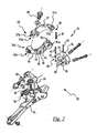
- FIG. 2 a first embodiment of a support 22 for a bicycle front gearshift 20 in accordance with the present invention is shown.
- the front gearshift 20 comprises the support 22 itself, intended to fasten the gearshift 20 to the frame of a bicycle (in particular to the seat post tube of the bicycle, indicated with 3 in the figure 1 relative to the prior art), a thrusting member 24 of the bicycle chain, like for example a chain guide (the chain is not shown since it is per sè conventional), intended to engage and move the chain, a front articulation arm 26 and a rear articulation arm 28, where the terms front and rear refer to the configuration in which the support is mounted on the bicycle.
- the two articulation arms 26 and 28 connect the chain guide 24 to the support 22 thanks to four pins 30, thus defining an articulated quadrilateral.
- the support 22 comprises an anchoring portion 32 to the seat post tube 3 of the bicycle and a coupling portion 34 with the articulation arms 26 and 28, said portions 32 and 34 being - in accordance with the present invention - structurally distinct from each other.
- the anchoring portion 32 in use is intended to embrace the seat post tube 3 of the bicycle and comprises a pair of jaws 36 and 37 joined at one of their ends through a hinge 38 and at the opposite end through a lock screw 40.
- the jaw 37 has a cap-shaped end 37a that is inserted into a forked end 36a of the jaw 36.
- the ends 37a and 36a have respective through holes 37c and 36c (one hole 37c on the end 37a and two holes 36c on the end 36a), which are aligned for the insertion of a rotation pin 39.
- the jaw 37 has, at the end 37d opposite the end 37a, an opening 37b crossed by the screw 40 whereas the jaw 36 has, at the end 36d opposite the end 36a, a threaded hole 36b in which the screw 40 engages.
- the screw 40 can cross a hole without threading provided on the jaw 36 instead of the threaded hole 36b, and be engaged in a nut (not illustrated).
- the coupling portion 34 is permanently associated with at least one of the articulation pins 30, for example by co-moulding or gluing, and comprises a seat for a second articulation pin 30.
- both of the pins 30 can be permanently or dismountably associated with the coupling portion 34.
- the anchoring portion 32 is removably associated with the coupling portion 34, in the example illustrated in figure 2 through rigid connecting elements such as a pair of pins 42 that are inserted into holes 44 of the coupling portion 34 and into holes 45 of the jaw 36 aligned with each other.
- a connecting part 33 specially formed in the anchoring portion 32 is defined by a ribbing 49.
- the coupling portion 34 comprises a groove 48 in which the ribbing 49 is inserted.
- the aligned holes 44 and 45 are made through the walls of the groove 48 and through the ribbing 49.
- connection between the anchoring portion 32 and the coupling portion 34 just described and illustrated in figure 2 is given purely as an example; a man skilled in the art will have no difficulty in understanding that any type of connection that makes a rigid coupling is suitable for the purpose.
- Figure 3 shows a second embodiment of the support according to the present invention, which is indicated with 22a.
- structural elements that are identical or equivalent from the functional point of view to those of the support 22 described above with reference to figure 2 shall be indicated with the same reference numerals and they shall not be described any further.
- the support 22a differs from the support 22 of figure 2 substantially in that the jaw 36 is associated with the coupling portion 34a through co-moulding.
- through holes 52 formed in the coupling portion 34a for the insertion of a pair of articulation pins 30 (not illustrated) are also shown.
- the jaws 36 and 37 of the anchoring portion 32 of the support 22 of figure 2 are integrally joined together at one end and engaged by a lock screw at the opposite end.
- the two jaws 36 and 37 of the anchoring portion 32 of figure 2 form a single jaw defining an elastic monolithic clip, which has a substantially annular shape.
- Such a clip is interrupted at a sector thereof so as to define two ends that can be coupled together.
- the anchoring portion 32 and the coupling portion 34 can be made with any material, like for example an aluminium alloy, a composite material or a polymer.
- composite material a material consisting of at least two components including a polymeric matrix and a filler for example comprising structural fibres, granules or powders.
- the structural fibres are preferably selected from the group consisting of carbon fibres, glass fibres, aramid fibres, ceramic fibres, boron fibres and combinations thereof. Carbon fibres are particularly preferred.
- the polymeric material is thermosetting and preferably comprises an epoxy resin. However, the use of a thermoplastic material is not excluded.
- structural composite materials those materials that contain structural fibres with a length of over five millimetres.
- the arrangement of said structural fibres in the polymeric material can be a random arrangement of pieces or small sheets of structural fibres, a substantially unidirectional ordered arrangement of fibres, a substantially bidirectional ordered arrangement of fibres or a combination of the above.
- reinforced composite materials materials comprising a polymeric matrix filled with fibres of a length shorter than or equal to five millimetres and/or with powders and/or with granules. It should be observed that the dimensions shown refer to the length of the fibre that can be found in a finished piece.
- the reinforced composite materials have a structural strength lower than that of composite structural materials, but in general they are suitable for injection moulding and they are easy to work, which is why they are particularly preferred for manufacturing the coupling portion 34, to which they also confer a considerable lightness. However, for such a coupling portion the use of a simple polymer is not excluded.
- Composite structural materials have a high structural strength and a very low linear thermal expansion coefficient, in general of the order of 5 ⁇ 10 -7 m/m°K, for which reason they are particularly preferred for manufacturing the anchoring portion 32, or at least one of the two jaws 36 and 37 of figures 2 and 3 .
- a less expensive alternative is to manufacture the anchoring portion 32 - or at least a part thereof, for example the jaw 36 of figures 2 and 3 - from metal, like an aluminium alloy and/or magnesium, which in any case has a linear thermal expansion coefficient of the order of 5 ⁇ 10 -6 m/m°K. In general, materials having a linear thermal expansion coefficient lower than 5 ⁇ 10 -5 m/m°K are acceptable to manufacture the anchoring portion 32.
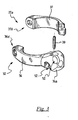
- FIGS 4-9 show a third embodiment of the support according to the present invention, which is indicated with 122.
- the support 122 is part of a bicycle front gearshift 120.
- the front gearshift 120 is a so-called motorised gearshift, of the type analogous to the one described in patent n° US 6679797 to the same Applicant.
- the gearshift 120 comprises a support 122 comprising an anchoring portion 132, substantially identical to the anchoring portion 32 of figure 2 , and a coupling portion 134, said portions 132 and 134 - in accordance with the present invention - being structurally distinct from each other.
- the main difference with respect to the gearshift 20 of figure 2 is given by the fact that the coupling portion 134 has a more complex shape than that of the portion 34 of figure 2 and is adapted to house a worm screw 102, actuated by an electric motor 105.
- a chain guide 24 is connected to the coupling portion 134 through the front articulation arm 26 and the rear articulation arm 28, which are movable in rotation about the pins 30, in a totally similar way to what has already been described in reference to the gearshift 20 of figure 2 .
- the front articulation arm 26 has an extension 127 terminating with an engagement portion 127a, carrying a nut screw, which engages with the worm screw 102.
- the worm screw 102 actuated by the electric motor 105, moves the engagement portion 127a of the extension 127, the arm 26 rotates about a pin 30 that is fixed with respect to the coupling portion 134, like a lever pivoted at the aforementioned pin 30, causing the movement of the chain guide 24.
- the support 122 which comprises the coupling portion 134 having a per sè complex shape, is easier to be moulded than the support for a front gearshift illustrated in patent n° US 6679797 to the same Applicant, since the coupling portion 134 is made separately from the anchoring portion 132.
- the residual tensions inside the coupling portion 134 are lower, since there are no long portions with a thin section (such as the anchoring portion 132) connected roughly to portions of large thickness (such as the coupling portion 134). In this way, the cooling of the pieces (in particular of the coupling portions 134) in the mould is substantially uniform and the residual tensions are very limited. This allows even pieces with a particularly complicated shape to be moulded (in particular coupling portions 134).
- the support 122 comprises a groove 148 of a shape such as to contain for the whole height thereof a connecting part 133 of a jaw 136.
- Two pins 142a and 142b cross the whole height of the connecting part 133 of the jaw 136 and not only a ribbing thereof as occurs in the support 22 of figure 2 .
- the groove 148 also comprises two deeper end areas 170 and 171 at the passing points of the pins 142a and 142b, so as to house corresponding widenings 170a and 171a projecting outside from the jaw 136.
- a fork-shaped end 136a of the jaw 136 is totally housed in the deeper end area 170 and is held here by the pin 142b, which thus acts as an articulation pin between the jaw 136 and the jaw 37, thus replacing the function of the pin 39 of the support 22 of figure 2 .
- the pin 142b preferably has a larger diameter than the pin 142a.
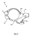
- figure 8 shows that the anchoring portion 132 is advantageously mounted on the seat post tube 3 of the bicycle with the jaw 136 facing towards the rear wheel 160 of the bicycle.
- the jaw 136 has a descending progression at the part 162 that, in use, is intended to face the rear wheel 160 of the bicycle. Thanks to this provision, the part 162 of jaw 136 that faces the rear wheel 160 remains farther away, with respect to the rest of the anchoring portion 132, from a plane Y that is perpendicular to the axis X and at which the distance between the wheel 160 and the seat post tube 3 of the bicycle is at its minimum.
- the connecting part 133 is defined in said part 162 of the jaw 136, and is housed in the groove 148, which also has a "skewed" shape.
- the groove 148 is substantially “inclined” with respect to a plane perpendicular to the axis X of the seat post tube 3.
- FIG 5 it can be seen how the openings 148a and 148b of the coupling portion 134, arranged at the opposite end portions of the groove 148 and from where the jaw 136 projects when mounted on the coupling portion 134, are not aligned with respect to a plane perpendicular to the axis X of the seat post tube 3, but are at different heights, so that the end portion 148b of said groove 148 facing towards the rear wheel 160 of the bicycle is lower than the other end portion 148a of the groove 148.
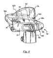
- Figure 7 shows the coupling portion 134 according to a point of view different to that of figure 6 .
- the pin 30 is integrated in the coupling portion 134, for example through co-moulding.
- the aforementioned pin 30 is intended to couple with the front articulation arm 26.
- the coupling portion 134 also comprises a pair of plates 173 faced to one other so as to form a chain guide and on which a respective hole 175 is formed, said holes 175 being aligned with each other for the passage of the other pin 30, intended to couple with the rear articulation arm 28.
- the coupling portion 134 is hollow so as to define a housing seat 177 for the worm screw 102.
- a seat 177 has a top opening 178, from the part of the chain guide 173 and of the co-moulded pin 30, for the access of the extension 127 of the front articulation arm 26.
- a cover 185 ( figure 4 ), fixedly fitted along the edge of the opening 178, protects the worm screw 102 and the portion 127a, shaped like a nut screw, of the extension 127 of the front articulation arm 26.
- the housing seat 177 is in communication with a tubular space 182 coaxial thereto and formed in a part 183 of the coupling portion 134, adapted to be coupled with an end of the electric motor 105 ( figure 4 ).
- the part 183 of the coupling portion 134 comprises an elastic clip 179, obtained by forming two wings 180 which are elastically deformable and integral with the coupling portion 134.
- the wings 180 are crossed by respective holes 181 which are aligned with each other for the passage of a bolt or locking screw (not shown).
- the assembly of the support for the bicycle front gearshift takes place in the following way.
- the anchoring portion (32 in figures 2 and 3 , 132 in figure 4 ) is opened by rotating the jaws (36 and 37 in figures 2 and 3 , 136 and 37 in figure 4 ) about the rotation pin 39 ( figures 2 and 3 ) or the pin 142b ( figure 5 ) of the hinge (38 in figures 2 and 6 ). It is thus possible to arrange the anchoring portion (32 in figures 2 and 3 , 132 in figure 4 ) around the seat post tube 3 of the bicycle.
- the jaws (36 and 37 in figures 2 and 3 , 136 and 37 in figure 4 ) are closed by rotating them about the rotation pin 39 ( figures 2 and 3 ) or the pin 142b ( figure 5 ), and are clamped around the seat post tube 3 through screwing of the screw 40.
- the anchoring portion comprises a monolithic clip
- such a clip is elastic, so that the two couplable ends can firstly be distanced to allow the arrangement of the clip about the seat post tube of the bicycle. Once the clip has elastically returned to its original position, the couplable ends are brought together by screwing a locking screw, until the clamping by deformation of the anchoring portion on the seat post tube is obtained.
- the clip 179 is clamped around the electric motor 105 and keeps it in operative connection with the worm screw 102 inserted in the housing seat 177, for example through an Oldham joint (not illustrated), housed in the tubular space 182 of the housing seat 177.
Landscapes
- Engineering & Computer Science (AREA)
- Chemical & Material Sciences (AREA)
- Combustion & Propulsion (AREA)
- Transportation (AREA)
- Mechanical Engineering (AREA)
- Steering Devices For Bicycles And Motorcycles (AREA)
- Clamps And Clips (AREA)
- Motorcycle And Bicycle Frame (AREA)
Applications Claiming Priority (1)
| Application Number | Priority Date | Filing Date | Title |
|---|---|---|---|
| IT001871A ITMI20071871A1 (it) | 2007-09-28 | 2007-09-28 | Supporto per cambio anteriore di bicicletta e cambio anteriore di bicicletta comprendente tale supporto |
Publications (1)
| Publication Number | Publication Date |
|---|---|
| EP2042423A1 true EP2042423A1 (fr) | 2009-04-01 |
Family
ID=40227953
Family Applications (1)
| Application Number | Title | Priority Date | Filing Date |
|---|---|---|---|
| EP08006142A Withdrawn EP2042423A1 (fr) | 2007-09-28 | 2008-03-28 | Support de levier de vitesse frontal d'une bicyclette et levier de vitesse frontal de bicyclette comportant un tel support |
Country Status (5)
| Country | Link |
|---|---|
| US (1) | US20090084926A1 (fr) |
| EP (1) | EP2042423A1 (fr) |
| JP (1) | JP2009083845A (fr) |
| IT (1) | ITMI20071871A1 (fr) |
| TW (1) | TW200932623A (fr) |
Families Citing this family (2)
| Publication number | Priority date | Publication date | Assignee | Title |
|---|---|---|---|---|
| US8387926B2 (en) * | 2010-12-08 | 2013-03-05 | Bendix Spicer Foundation Brake Llc | Clamping cam tube support |
| ITMI20131641A1 (it) * | 2013-10-04 | 2015-04-05 | Campagnolo Srl | Dispositivo di arresto dello spostamento laterale di una catena di bicicletta |
Citations (3)
| Publication number | Priority date | Publication date | Assignee | Title |
|---|---|---|---|---|
| US20030228947A1 (en) * | 2000-09-15 | 2003-12-11 | Campagnolo, Srl | Front bycycle derailleur |
| EP1630093A2 (fr) * | 2004-08-30 | 2006-03-01 | Shimano Inc. | Dérailleur avant pour une bicyclette |
| EP1787902A2 (fr) * | 2005-11-21 | 2007-05-23 | Shimano Inc. | Dérailleur avant avec dispositif de fixation |
Family Cites Families (8)
| Publication number | Priority date | Publication date | Assignee | Title |
|---|---|---|---|---|
| US3863512A (en) * | 1973-11-09 | 1975-02-04 | California Progressive Prod | Shift mechanism for derailleur drive |
| US4041788A (en) * | 1975-07-30 | 1977-08-16 | California Progressive Products, Inc. | Electrical control for derailleur drive |
| US4922164A (en) * | 1988-10-03 | 1990-05-01 | Sarcos Group | Eccentric motion motor |
| IT1266817B1 (it) * | 1994-02-24 | 1997-01-21 | Campagnolo Srl | Dispositivo di cambio di velocita' per biciclette. |
| US5514041A (en) * | 1994-11-21 | 1996-05-07 | Hsu; Yi-Hsung | Electronic bicycle derailleur control apparatus |
| US6162140A (en) * | 1998-12-18 | 2000-12-19 | Shimano, Inc. | Motor driven derailleur |
| IT1307681B1 (it) * | 1999-04-13 | 2001-11-14 | Campagnolo Srl | Deragliatore posteriore di bicicletta. |
| IT1320581B1 (it) * | 2000-08-03 | 2003-12-10 | Campagnolo Srl | Deragliatore anteriore di bicicletta con motore elettrico di comando e riduttore ad ingranaggi. |
-
2007
- 2007-09-28 IT IT001871A patent/ITMI20071871A1/it unknown
-
2008
- 2008-03-28 EP EP08006142A patent/EP2042423A1/fr not_active Withdrawn
- 2008-09-17 US US12/212,281 patent/US20090084926A1/en not_active Abandoned
- 2008-09-26 TW TW097137246A patent/TW200932623A/zh unknown
- 2008-09-26 JP JP2008247676A patent/JP2009083845A/ja active Pending
Patent Citations (3)
| Publication number | Priority date | Publication date | Assignee | Title |
|---|---|---|---|---|
| US20030228947A1 (en) * | 2000-09-15 | 2003-12-11 | Campagnolo, Srl | Front bycycle derailleur |
| EP1630093A2 (fr) * | 2004-08-30 | 2006-03-01 | Shimano Inc. | Dérailleur avant pour une bicyclette |
| EP1787902A2 (fr) * | 2005-11-21 | 2007-05-23 | Shimano Inc. | Dérailleur avant avec dispositif de fixation |
Also Published As
| Publication number | Publication date |
|---|---|
| JP2009083845A (ja) | 2009-04-23 |
| TW200932623A (en) | 2009-08-01 |
| US20090084926A1 (en) | 2009-04-02 |
| ITMI20071871A1 (it) | 2009-03-29 |
Similar Documents
| Publication | Publication Date | Title |
|---|---|---|
| CN218141972U (zh) | 自行车换挡机构及用于自行车换挡机构的马达传动单元 | |
| TWI424936B (zh) | 自行車右曲柄臂組件及其曲柄臂與前扣鏈齒輪 | |
| US7025698B2 (en) | Front derailleur with annular chain guide, bicycle and method of operation | |
| EP2441656B1 (fr) | Élément d'espaceur pour pignons d'un ensemble de pignons d'une roue arrière de bicyclette | |
| EP1818252B1 (fr) | Pédalier de bicyclette et méthode pour fabriquer un tel pèdalier | |
| TWI382944B (zh) | 自行車後撥鏈器 | |
| EP2065297B1 (fr) | Dérailleur arrière de bicyclette | |
| US20100058889A1 (en) | Bicycle component and method for making such a component | |
| CN101362501A (zh) | 用于自行车的链轮模块以及包括这种模块的链轮组件 | |
| US7951028B2 (en) | Front derailleur and chain guide | |
| US20050040304A1 (en) | Fixing apparatus | |
| EP2042423A1 (fr) | Support de levier de vitesse frontal d'une bicyclette et levier de vitesse frontal de bicyclette comportant un tel support | |
| EP1792821A1 (fr) | Ensemble de pédalier | |
| EP2052958A1 (fr) | Changement de vitesses pour bicyclette | |
| US20240199163A1 (en) | Method for producing a handlebar arrangement | |
| US20100320814A1 (en) | Support and holding device for bicycle saddle | |
| EP1840023B1 (fr) | Assemblage de pédalier de vélo et éléments associés | |
| EP1792819A1 (fr) | Ensemble de pédalier | |
| US12091131B2 (en) | Insert undercut | |
| US20130263689A1 (en) | Bike stem apparatus | |
| TWI910273B (zh) | 用於人力車輛的操作裝置 | |
| EP4429939B1 (fr) | Dérailleur arrière ayant une cage de chaîne monobloc | |
| US4167125A (en) | Rear-wheel mounting for bicycle | |
| US20220221610A1 (en) | Metal Detector | |
| EP2110304A1 (fr) | Dérailleur de bicyclette |
Legal Events
| Date | Code | Title | Description |
|---|---|---|---|
| PUAI | Public reference made under article 153(3) epc to a published international application that has entered the european phase |
Free format text: ORIGINAL CODE: 0009012 |
|
| AK | Designated contracting states |
Kind code of ref document: A1 Designated state(s): AT BE BG CH CY CZ DE DK EE ES FI FR GB GR HR HU IE IS IT LI LT LU LV MC MT NL NO PL PT RO SE SI SK TR |
|
| AX | Request for extension of the european patent |
Extension state: AL BA MK RS |
|
| AKX | Designation fees paid | ||
| REG | Reference to a national code |
Ref country code: DE Ref legal event code: 8566 |
|
| STAA | Information on the status of an ep patent application or granted ep patent |
Free format text: STATUS: THE APPLICATION IS DEEMED TO BE WITHDRAWN |
|
| 18D | Application deemed to be withdrawn |
Effective date: 20091002 |