EP2042441B1 - Zweiteilige Schale zur Aufnahme von Lebensmitteln - Google Patents
Zweiteilige Schale zur Aufnahme von Lebensmitteln Download PDFInfo
- Publication number
- EP2042441B1 EP2042441B1 EP08165322A EP08165322A EP2042441B1 EP 2042441 B1 EP2042441 B1 EP 2042441B1 EP 08165322 A EP08165322 A EP 08165322A EP 08165322 A EP08165322 A EP 08165322A EP 2042441 B1 EP2042441 B1 EP 2042441B1
- Authority
- EP
- European Patent Office
- Prior art keywords
- container
- lateral
- hollow container
- sides
- tray according
- Prior art date
- Legal status (The legal status is an assumption and is not a legal conclusion. Google has not performed a legal analysis and makes no representation as to the accuracy of the status listed.)
- Active
Links
- 235000013305 food Nutrition 0.000 title description 15
- 239000002131 composite material Substances 0.000 title 1
- 239000004033 plastic Substances 0.000 claims abstract description 17
- 229920003023 plastic Polymers 0.000 claims abstract description 17
- 230000002093 peripheral effect Effects 0.000 claims abstract description 8
- 230000003014 reinforcing effect Effects 0.000 claims description 42
- 239000000463 material Substances 0.000 claims description 15
- 238000003856 thermoforming Methods 0.000 claims description 5
- 238000001746 injection moulding Methods 0.000 claims description 4
- 238000005520 cutting process Methods 0.000 claims description 3
- 238000007789 sealing Methods 0.000 claims description 3
- 230000002787 reinforcement Effects 0.000 abstract description 11
- 238000006073 displacement reaction Methods 0.000 abstract 1
- 239000003292 glue Substances 0.000 description 6
- 239000002699 waste material Substances 0.000 description 6
- 238000004064 recycling Methods 0.000 description 5
- 238000013461 design Methods 0.000 description 3
- 230000015556 catabolic process Effects 0.000 description 2
- 238000006731 degradation reaction Methods 0.000 description 2
- 230000007613 environmental effect Effects 0.000 description 2
- 238000004519 manufacturing process Methods 0.000 description 2
- 238000012545 processing Methods 0.000 description 2
- 230000000284 resting effect Effects 0.000 description 2
- 238000000926 separation method Methods 0.000 description 2
- 239000000126 substance Substances 0.000 description 2
- 239000000853 adhesive Substances 0.000 description 1
- 238000004026 adhesive bonding Methods 0.000 description 1
- 230000001070 adhesive effect Effects 0.000 description 1
- 238000005452 bending Methods 0.000 description 1
- 238000004891 communication Methods 0.000 description 1
- 230000000295 complement effect Effects 0.000 description 1
- 230000008878 coupling Effects 0.000 description 1
- 238000010168 coupling process Methods 0.000 description 1
- 238000005859 coupling reaction Methods 0.000 description 1
- 238000009826 distribution Methods 0.000 description 1
- 230000000694 effects Effects 0.000 description 1
- 238000005516 engineering process Methods 0.000 description 1
- 238000010438 heat treatment Methods 0.000 description 1
- 238000000034 method Methods 0.000 description 1
- 238000012986 modification Methods 0.000 description 1
- 230000004048 modification Effects 0.000 description 1
- 239000010816 packaging waste Substances 0.000 description 1
- 239000002985 plastic film Substances 0.000 description 1
- 229920006255 plastic film Polymers 0.000 description 1
- 239000013502 plastic waste Substances 0.000 description 1
- 230000000717 retained effect Effects 0.000 description 1
- 230000002441 reversible effect Effects 0.000 description 1
- 238000007665 sagging Methods 0.000 description 1
- 238000005728 strengthening Methods 0.000 description 1
- 238000013519 translation Methods 0.000 description 1
- 238000003466 welding Methods 0.000 description 1
Images


Classifications
-
- B—PERFORMING OPERATIONS; TRANSPORTING
- B65—CONVEYING; PACKING; STORING; HANDLING THIN OR FILAMENTARY MATERIAL
- B65D—CONTAINERS FOR STORAGE OR TRANSPORT OF ARTICLES OR MATERIALS, e.g. BAGS, BARRELS, BOTTLES, BOXES, CANS, CARTONS, CRATES, DRUMS, JARS, TANKS, HOPPERS, FORWARDING CONTAINERS; ACCESSORIES, CLOSURES, OR FITTINGS THEREFOR; PACKAGING ELEMENTS; PACKAGES
- B65D25/00—Details of other kinds or types of rigid or semi-rigid containers
- B65D25/34—Coverings or external coatings
- B65D25/36—Coverings or external coatings formed by applying sheet material
Definitions
- the present invention relates to trays for containing foods, such as prepared dishes.
- the trays for containing food comprise a hollow container delimiting at least one cavity between a container bottom and a container side peripheral wall having at least two opposite first sides generally parallel to one another, with a main opening face defining a plan for opening the cavity upwards.
- trays are generally made of plastics with relatively thick walls, that is to say with a relatively thick container bottom and relatively thick lateral peripheral wall.
- the relatively large thickness of the walls of the trays is necessary to ensure sufficient stiffening of the trays so that they can be easily handled. and that they are not deformed by the foods they contain.
- the side peripheral walls of the trays must be rigid enough to allow stacking trays without risking their degradation.
- the main stiffening means used in these known trays is to provide that the walls of the trays have a thickness sufficient to prevent their deformations.
- a thickness of 0.6 mm is usually suitable for molded or thermoformed plastic trays.
- a further disadvantage of known trays is that the processing of plastics is very expensive. Thus, the larger the quantity of plastic material to be treated, the higher the cost of this treatment. This high cost of processing plastic packaging waste has a logical effect on the price that the consumer has to pay when he buys the food in the trays.
- the trays for containing food include a generally plastic hollow container and an outer reinforcing structure having a bottom wall in close proximity to the container bottom and parallel side flaps two by two which are in close proximity to the respective outer faces of the container sides.
- This second type of tray has the advantage of using a smaller amount of plastic, because the reinforcing structure improves the mechanical strength of the tray.
- the wall of the hollow container may be thinner.
- this second type of tray has a first drawback which is to require the addition of an additional element reported, namely the glue.
- a second disadvantage is that the adhesive is a chemical substance that does not easily recycle and that can be harmful to the environment when it is burned for example during the treatment of waste.
- the problem proposed by the present invention is to design a tray for containing food which, while being rigid enough to be transported and stacked, minimizes the environmental impact through a smaller amount of hard-to-recycle plastic waste generated by such a container compared to known trays.
- the invention aims to facilitate, after use, the recycling of the materials constituting the tray.
- the invention also facilitates the assembly of the tray without adding additional elements.
- the invention provides the tray described in claim 1.
- this tray as a combination of two elements, namely a hollow container and an external structure of reinforcement, allows to combine the mechanical and ecological properties of each element.
- the hollow container may have less mechanical properties, and may therefore be formed of a thinner wall. Such a hollow container thus generates less waste and therefore has a lower environmental impact, even if it is made of material rather difficult to recycle such as plastic, suitable for being in contact with the contents of the tray.
- the plastic material makes it possible, for example, to produce a hollow container that is waterproof and / or insensitive to moisture.
- the reinforcing structure is designed to mechanically reinforce the hollow container by preventing the bottom of the container from sagging under the action of the weight of the food contained in the container, and by preventing sidewall bends during stacking.
- the reinforcing structure is not in contact with the contents of the tray, and can therefore be made of a different material and more easily recyclable, for example cardboard.
- the mechanical combination of the container bottom with the bottom wall increases the mechanical properties of the tray.
- the tray will not sag under the weight of the food it contains.
- the mechanical combination of the first two sides with the two first side flaps increases the mechanical properties of the tray.
- the tray can be easily stacked.
- the mechanical assembly of the hollow container and the reinforcing structure is provided by separable mechanical fastening means.
- the hollow container is made of plastic, and that its thin wall has a thickness of between about 0.2 and 0.4 millimeters, preferably about 0.3 millimeters.
- Plastics are easy and inexpensive to implement, in particular by thermoforming.
- the trays of the prior art usually have a thickness of at least 0.6 millimeters, in the case of similar mechanical strengths.
- the container of the invention uses a hollow container of thickness less than half.
- the amount of waste generated by the tray of the invention is therefore about half as much.
- the hollow container is of food plastic material.
- the combination of the first assembly groove, the bosses, the first two lateral flaps and flaps constitutes said separable mechanical coupling means: the mechanical assembly of the two elements - hollow container and reinforcement structure - is effected by a kind of reversible snap.
- the hollow container can be engaged by simple translation into the external reinforcing structure and is then retained in said structure by simple snapping.
- the separation of the hollow container away from the reinforcement structure can be performed by sufficient traction between the two elements, which is a simple and fast operation, allowing selective sorting.
- Such a hollow container design only requires a mold modification. No additional items such as glue should be added for assembly.
- the manufacture of this hollow container is simple and technology (thermoforming or injection molding) to achieve it is known, widespread and inexpensive.
- the absence of glue facilitates and improves the recycling of materials.
- the first two sides each comprise at least two disjointed bosses positioned near the longitudinal ends of the first two sides.
- the at least one boss has an oblong shape whose major axis is substantially parallel to the main opening face and has a length of about 2 centimeters.
- This configuration allows the assembly between the hollow container and the reinforcement structure to be made over a greater length. Thanks to a better distribution of forces, the assembly is mechanically efficient and reliable.
- the four sides of the tray comprise upper radial facets substantially coplanar and defining a lidding surface.
- Lidding is a simple and inexpensive method of closing a cavity. It consists in gluing a plastic film on a peripheral cavity surface. It allows a better conservation of the food contained in a tray, and it is a privileged space of communication with the consumers.
- the hollow container is made in one piece, by thermoforming a sheet of thermoformable material of about 0.3 millimeters thick, or by injection molding.
- thermoforming and injection molding are well known and inexpensive.
- the external reinforcing structure is made of cardboard.
- the cardboard is inexpensive and easy to implement. It has good mechanical properties. It is easy to cut and fold. It has good properties for recycling.
- the external reinforcing structure is made by cutting a strip of sheet material and folding along transverse fold lines into four successive sections each forming one of the four lateral flaps, each section having an edge. lateral to longitudinal fold line to form a flap and having the other lateral side with longitudinal fold line to form a portion of the bottom wall.
- This configuration is simple to perform. It is thus easy to form by simple folding and bonding steps an external reinforcing structure which is mechanically very strong.
- the transverse fold lines are divergent.
- This configuration makes it easy to obtain oblique lateral flaps.
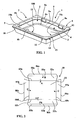
- the hollow container 1 comprises a cavity 2 bounded by a container bottom 3 and a container side peripheral wall 4 forming two opposite first sides 5a and 5b and two opposite second sides 15a and 15b.
- the cavity 2 is open upwards according to an opening face 7.
- the lateral peripheral container wall 4 of the hollow container 1 has a slight clearance ⁇ ( figure 4 ), allowing the stacking of superposed hollow containers.
- the hollow container 1 has a substantially rectangular shape whose four corners are substantially rounded. It is made of thermoformed plastic material, from a plate whose thickness is about 0.2 to 0.4 millimeters, advantageously about 0.3 millimeters.
- the first two opposite sides 5a and 5b of hollow container 1 each comprise, near their opening edges 6a and 6b, a first upper radial facet 9 which expands outwards and is extended by a first descending lip 10 to constitute a first assembly groove 11 open downwards.
- the first two opposite sides 5a and 5b of container each comprise two bosses 8a on their outer face. These bosses 8a are located near the longitudinal ends such as the ends 105a and 205a of the first two opposite sides 5a and 5b of the hollow container 1, and away from the opening edges 6a and 6b.
- each boss 8a is disjoint and each boss 8a has an oblong shape whose major axis is substantially parallel to the main opening face 7 and has a length of about 2 centimeters, for a tray of about 15 centimeters in length, 10 centimeters wide and 3 centimeters high.
- the two second sides 15a and 15b of the hollow container 1 each comprise a second upper radial face 12 which develops outwardly and which is extended by a second descending lip 13 to form a second connecting groove 14 open downwards.
- the first upper radial facets 9 and the second upper radial facets 12 are substantially coplanar, defining a sealing surface 100.
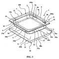
- the outer reinforcing structure 50 comprises a bottom wall 51, two first lateral flaps 52a and 52b opposite generally parallel to each other, and two second lateral flaps 57a and 57b. It is made of cardboard, cut and folded from a blank.
- the first two lateral flaps 52a and 52b each connect, according to their upper edge 53a and 53b, to a flap 55a and 55b.
- the flaps 55a and 55b each have a lower edge 56a and 56b, and their height is little greater than the distance between the bosses 8a and the corresponding opening edge 6a or 6b.
- the two second lateral flaps 57a and 57b each comprise an upper edge 58a or 58b.
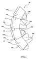
- the figure 3 illustrates elements 1 and 50 of Figures 1 and 2 and their relative position relative to each other, just before assembly.
- the bottom wall 51 is positioned in the immediate vicinity of the external face of the container bottom 3, and the first two lateral flaps 52a and 52b are positioned in close proximity to the external faces of the respective first and opposite opposite sides 5a and 5b of hollow containers. 1.
- the flaps 55a and 55b of the outer reinforcing structure 50 along the upper edges 53a and 53b must be folded inward as indicated by the arrows B ( figure 2 ), and fold inward the first two lateral flaps 52a and 52b of the external reinforcing structure 50 along a respective fold line 60a or 60b as indicated by the arrows A ( figure 2 ).
- the first two lateral flaps 52a and 52b of the external reinforcing structure 50 are folded according to the arrows A ( figure 2 ) to ensure the engagement of the upper edges 53a and 53b of the first two lateral flaps 52a and 52b of the external reinforcing structure 50 in the first connecting groove 11 of the hollow container 1.
- the flaps 55a and 55b tend to unfold and come to lock by their lower edge 56a and 56b resting against the upper face of the bosses 8a.
- the two second lateral flaps 57a and 57b of the external reinforcing structure 50 are also folded along the fold lines 60c and 60d as indicated by the arrows C ( figure 2 ) to engage the upper edge 58a, 58b of each second lateral flap 57a, 57b in the second connecting groove 14 of the hollow container 1.
- the figure 4 illustrates the hollow container 1 and the external reinforcing structure 50 in their assembled state.
- each first lateral flap 52a and 52b is engaged in the corresponding first connecting groove 11 of the hollow container 1, and the flap 55a and 55b abuts by its respective lower edge 56a or 56b on the face upper boss 8a corresponding, to oppose the downward movement of the outer reinforcing structure 50.
- the natural elasticity of the material forming the outer reinforcing structure 50 tends to rotate the flaps 55a and 55b inwardly, and the first assembly groove 11 opposes the outward spacing of the two first lateral flaps 52a and 52b of hollow container 1.
- Sufficient traction exerted by a user between the hollow container 1 and the external reinforcing structure 50 allows them to separate from one another by bending the flaps, for selective recycling for example.
- the first assembly groove 11, the bosses 8a, the two first lateral flaps 52a, 52b, and the flaps 55a, 55b constitute separable mechanical fastening means 8, and ensure the assembly without adding elements. outside such as glue.
- the upper radial facets 9 and 12, coplanar, define a sealing surface 100.
- this operation is usually done by welding with a heating knife and of an anvil.
- the anvil must be able to be placed in the lower face of the radial facets 9 and 12, in the assembly grooves 11 and 14. For this, it firstly carries the lidding of the hollow container 1 unreinforced, then assembles the hollow container 1 and sealed the structure external reinforcement 50 to make the tray.
- the figures represent a relatively flat tray, that is to say whose depth is significantly lower than its other dimensions.
- the invention applies equally well to deeper trays, pot type, having for example volumes of 500 milliliters and more.
- the rigidity aspect is all the more critical that the tray is deep, but the invention ensures a satisfactory rigidity in all usual cases.
- the figure 5 illustrates a second embodiment of the tray.
- the tray comprises a hollow container 1 which is deeper than on the figure 1 , and an external structure of reinforcement 50 more resistant than on the Figures 2 to 4 .
- the same essential means as in the embodiment of the preceding figures are identified by the same reference numerals, and will not all be described again.
- the hollow container 1 of the figure 5 has a shape similar to that illustrated on the figure 1 , with the exception of the depth which is superior, and with the exception of the shape of the bosses.
- the external structure of reinforcement illustrated on the figure 5 has a shape similar to that illustrated on the Figures 2 to 4 , adding the presence of two additional flaps, and adding the fact that the adjacent side flaps are further secured to each other.
- the hollow container 1 thus comprises two opposite first container sides 5a and 5b and two opposite second container sides 15a and 15b.
- Each of the first and second container sides 5a, 5b, 15a and 15b respectively has on its outer face a boss such as the bosses 8a or 18a, of oblong shape whose major axis is substantially parallel to the main opening face 7, and disposed away from a respective opening edge 6a, 6b, 6c or 6d.
- the external reinforcing structure 50 comprises two first lateral flaps 52a and 52b and two second lateral flaps 57a and 57b.
- the two second lateral flaps 57a and 57b each connect, according to their upper edge 58a or 58b, to a flap 155a or 155b.
- the flaps 155a and 155b each have a respective lower edge 156a or 156b, and their height is little greater than the difference between the corresponding boss such as the boss 18a and the corresponding opening edge 6c or 6d.
- the bottom wall 51 is positioned in the immediate vicinity of the outer face of the container bottom 3
- the first two lateral flaps 52a and 52b are positioned in close proximity to the external faces of the respective first two opposite sides 5a and 5b of the hollow container 1
- the first two lateral flaps 52a and 52b and the two second lateral flaps 57a and 57b have previously been raised in a ring and assembled to one another, and the flaps 55a, 55b, 155a and 155b have previously been folded towards the inside of the door.
- external reinforcing structure 50 along the upper edges 53a, 53b, 58a and 58b.
- the first two lateral flaps 52a and 52b and the second two lateral flaps 57a and 57b of the external reinforcing structure 50 are dimensioned so as to allow the engagement of the upper edges 53a, 53b, 58a and 58b of the respective lateral flaps of the structure. external reinforcement 50 in the respective assembly groove 11 or 14 of the hollow container 1.
- the flaps 55a, 55b, 155a and 155b then tend to unfold and come to lock by their respective lower edge 56a, 56b, 156a or 156b resting against the face upper of a respective boss such as bosses 8a or 18a.
- the figure 6 illustrates the realization of the external reinforcement structure 50 of the figure 5 .
- the outer reinforcing structure 50 is a strip of sheet material, made by cutting a blank according to a predefined contour as shown.
- transverse fold lines L1, L2 and L3 are formed, defining four successive sections each forming one of the four lateral flaps 52a, 57b, 52b and 57a.
- Each section has a longitudinal fold line side edge to form a flap 55a, 155a, 55b or 155b, and its other side side is provided with longitudinal fold lines 60a, 60c, 60b and 60d to form a portion of the wall. background 51.
- transverse fold lines L1, L2, L3 are divergent so that once assembled the tray has oblique lateral flaps.
Landscapes
- Engineering & Computer Science (AREA)
- Mechanical Engineering (AREA)
- Packages (AREA)
- Stackable Containers (AREA)
- Table Devices Or Equipment (AREA)
Claims (12)
- Schale zur Aufnahme von Lebensmitteln, umfassend einen Behälter (1), der wenigstens eine Vertiefung (2) zwischen einem Behälterboden (3) und einer umlaufenden Seitenwand (4) begrenzt, die wenigstens zwei erste, einander im wesentlichen parallel gegenüberliegende Seiten (5a, 5b) hat, wobei eine Hauptöffnungsseite (7) eine Öffnungsebene der Vertiefung (2) nach oben begrenzt, und umfassend ferner eine äußere Verstärkungsstruktur (50) mit einer Bodenwand (51) und wenigstens zwei ersten seitlichen, einander im wesentlichen parallel gegenüberliegenden Flügeln (52a, 52b), wobei:- sich die Bodenwand (51) unmittelbar anschließend an die Außenseite des Behälterbodens (3) befindet,- sich die zwei ersten seitlichen Flügel (52a, 52b) in unmittelbarer Nähe der Außenseiten der beiden ersten Seiten (5a, 5b) des Behälters befinden,- der Behälter (1) dünnwandig ausgebildet ist,- die beiden ersten Seiten (5a, 5b) des Behälters jeweils ein erste obere, radiale Randfläche (9) haben, die sich nach außen erstreckt und an die sich ein erste Randlippe (10) anschließt, die nach unten weist, wodurch eine erste Verbindungs-Hohlkehle (11) gebildet wird, die nach unten offen ist und dadurch ein Auseinanderspreizen der beiden ersten seitlichen Flügel (52a, 52b) nach außen verhindert,dadurch gekennzeichnet, dass:- die beiden ersten Seiten (5a, 5b) des Behälters an ihrer Außenfläche jeweils wenigstens einen Vorsprung (8a) aufweisen, der mit den beiden zugeordneten ersten seitlichen Flügeln (52a, 52b) zusammenwirkt, um eine Abwärtsbewegung der äußeren Verstärkungsstruktur (50) zu verhindern,- die beiden ersten seitlichen Flügel (52a, 52b) an ihrem oberen Rand (53a, 53b) mit jeweils einer Lasche (55a, 55b) verbunden sind, die nach innen umgefalzt ist und die Tendenz hat, sich von dem zugehörigen ersten seitlichen Flügel (52a, 52b) elastisch wegzuspreizen, und- im zusammengesetzten Zustand der obere Rand (53a, 53b) jedes ersten seitlichen Flügels (52a, 52b) in die zugeordnete erste Verbindungs-Hohlkehle (11) des Behälters (1) eingreift und die Lasche (55a, 55b) mit ihrem unteren Rand (56a, 56b) an der Oberseite des zugehörigen Vorsprungs (8a) zur Anlage kommt.
- Schale nach Anspruch 1, dadurch gekennzeichnet, dass der Behälter (1) aus Kunststoff besteht und seine dünne Wand eine Wandstärke zwischen etwa 0,2 und 0,4 mm hat, vorzugsweise in der Größenordnung von 0,3 mm.
- Schale nach einem der Ansprüche 1 oder 2, dadurch gekennzeichnet, dass die beiden ersten Seiten (5a, 5b) jeweils wenigstens zwei voneinander getrennte Vorsprünge (8a) haben, die in der Nähe der Längsenden (105a, 205a) der beiden ersten Seiten (5a, 5b) liegen.
- Schale nach einem der Ansprüche 1 bis 3, dadurch gekennzeichnet, dass wenigstens ein Vorsprung (8a) eine längliche Form hat, deren große Achse im wesentlichen parallel zu der Hauptöffnungsseite (7) verläuft und eine Länge von etwa 2 cm hat.
- Schale nach einem der Ansprüche 1 bis 4, dadurch gekennzeichnet, dass:- der Behälter (1) zwei zweite Seiten (15a, 15b) hat, von denen jede eine zweite obere, radiale Randfläche (12) aufweist, die sich nach außen erstreckt und an die sich eine zweite Randlippe (13) anschließt, die nach unten weist, wodurch eine zweite Verbindungs-Hohlkehle (14) gebildet wird, die nach unten offen ist,- die äußere Verstärkungsstruktur (50) weiterhin zwei zweite seitliche Flügel (57a, 57b) mit jeweils einem oberen Rand (58a, 58b) hat, und- im zusammengebauten Zustand der obere Rand (58a, 58b) jedes zweiten seitlichen Flügels (57a, 57b) in die zweite Verbindungs-Hohlkehle (14) des Behälters (1) eingreift.
- Schale nach einem der Ansprüche 1 bis 4, dadurch gekennzeichnet, dass:- der Behälter (1) zwei zweite Seiten (15a, 15b) hat, von denen jede eine zweite obere, radiale Randfläche (12) aufweist, die sich nach außen erstreckt und an die sich eine zweite Randlippe (13) anschließt, die nach unten weist, wodurch eine zweite Verbindungs-Hohlkehle (14) gebildet wird, die nach unten offen ist,- die beiden zweiten Seiten (15a, 15b) des Behälters an ihrer Außenfläche wenigstens einen Vorsprung (18a) haben,- die äußere Verstärkungsstruktur (50) weiterhin zwei zweite seitliche Flügel (57a, 57b) hat, von denen jeder an seinem oberen Rand (58a, 58b) mit einer Lasche (155a, 155b) verbunden ist, die nach innen umgefalzt ist und die Tendenz hat, sich von dem zugehörigen zweiten seitlichen Flügel (57a, 57b) elastisch wegzuspreizen, und- im zusammengesetztem Zustand der obere Rand (58a, 58b) jedes zweiten seitlichen Flügels (57a, 57b) in die zugeordnete zweite Verbindungs-Hohlkehle (14) des Behälters (1) eingreift und die Lasche (155a, 155b) mit ihrem unteren Rand (156a, 156b) an der Oberseite eines zugehörigen Vorsprungs (18a) zur Anlage kommt.
- Schale nach Anspruch 6, dadurch gekennzeichnet, dass die äußere Verstärkungsstruktur (50) durch Ausschneiden aus einer Wand aus Blattmaterial und Falzen an quer verlaufenden Knicklinien (L1, L2, L3) in vier aufeinander folgende Abschnitte gebildet ist, von denen jeder einen der vier seitlichen Flügel (52a, 57b, 52b, 57a) bildet, wobei jeder Abschnitt einen Seitenrand mit längs verlaufender Knicklinie zur Bildung einer Lasche (55a, 155a, 55b, 155b) sowie am anderen Seitenrand mit längs verlaufender Knicklinie (60a, 60c, 60b, 60d) zur Bildung eines Teils der Bodenwand (51) hat.
- Schale nach Anspruch 7, dadurch gekennzeichnet, dass die quer verlaufenden Knicklinien (L1, L2, L3) divergieren.
- Schale nach einem der Ansprüche 5 bis 8, dadurch gekennzeichnet, dass die vier Seiten (5a, 5b, 15a, 15b) obere, radiale Randflächen (9, 12) haben, die im wesentlichem in einer Ebene liegen und eine Deckelfläche (100) bilden.
- Schale nach einem der Ansprüche 1 bis 9, dadurch gekennzeichnet, dass der Behälter (1) aus lebensmittelechtem Kunststoff besteht.
- Schale nach einem der Ansprüche 1 bis 10, dadurch gekennzeichnet, dass der Behälter (1) einstückig durch Thermoverformung eines warmverformbaren Folienmaterials mit einer Wandstärke von etwa 0,3 mm oder durch Spritzguss hergestellt ist.
- Schale nach einem der Ansprüche 1 bis 11, dadurch gekennzeichnet, dass die äußere Verstärkungsstruktur (50) aus Karton besteht.
Applications Claiming Priority (1)
| Application Number | Priority Date | Filing Date | Title |
|---|---|---|---|
| FR0757870A FR2921345A1 (fr) | 2007-09-26 | 2007-09-26 | Barquette combinee pour contenir des aliments |
Publications (2)
| Publication Number | Publication Date |
|---|---|
| EP2042441A1 EP2042441A1 (de) | 2009-04-01 |
| EP2042441B1 true EP2042441B1 (de) | 2012-02-22 |
Family
ID=39322339
Family Applications (1)
| Application Number | Title | Priority Date | Filing Date |
|---|---|---|---|
| EP08165322A Active EP2042441B1 (de) | 2007-09-26 | 2008-09-26 | Zweiteilige Schale zur Aufnahme von Lebensmitteln |
Country Status (3)
| Country | Link |
|---|---|
| EP (1) | EP2042441B1 (de) |
| AT (1) | ATE546375T1 (de) |
| FR (1) | FR2921345A1 (de) |
Family Cites Families (2)
| Publication number | Priority date | Publication date | Assignee | Title |
|---|---|---|---|---|
| US4801017A (en) * | 1986-10-17 | 1989-01-31 | Aldo Artusi | Container, particularly for receiving foods |
| US5709308A (en) * | 1995-06-06 | 1998-01-20 | Gics & Vermee, L.P. | Food product container including a tray and a jacket and an associated food product package |
-
2007
- 2007-09-26 FR FR0757870A patent/FR2921345A1/fr not_active Withdrawn
-
2008
- 2008-09-26 AT AT08165322T patent/ATE546375T1/de active
- 2008-09-26 EP EP08165322A patent/EP2042441B1/de active Active
Also Published As
| Publication number | Publication date |
|---|---|
| ATE546375T1 (de) | 2012-03-15 |
| FR2921345A1 (fr) | 2009-03-27 |
| EP2042441A1 (de) | 2009-04-01 |
Similar Documents
| Publication | Publication Date | Title |
|---|---|---|
| EP2872409B1 (de) | Kastenförmige verpackung aus zwei materialien zum verpacken eines produktes, und herstellungsverfahren | |
| EP0052021B1 (de) | Kartonbehälter mit Kunststoffauskleidung und mit einem einstückigen Umfangsrahmen und Verfahren zu seiner Herstellung | |
| FR2975973A1 (fr) | Procede de fabrication d'une barquette etanche en carton pour la realisation d'un emballage permettant le conditionnement de produits | |
| FR2887529A1 (fr) | Boite en carton ondule a volets ajoures et ensemble de decoupes pour obtenir une telle boite | |
| EP0647566B1 (de) | Faltbarer, wiederverwendbarer und stapelbarer Mehrzweckbehälter aus Kunststoff | |
| FR2460257A1 (fr) | Recipient en forme de bac rectangulaire et flan de carton destine a sa realisation | |
| EP0930999A1 (de) | Verpackung, verfahren und vorrichtung zum verpacken einer gruppe von artikeln unbestimmten volumens | |
| EP3141373A1 (de) | Verfahren und maschine zur herstellung von thermoverschweissten verbundschalen und verbundschalen | |
| EP2905240B1 (de) | Lebensmittelverpackung mit wiederverschließbarem Deckel | |
| FR2979329A1 (fr) | Barquette composite a imbrication | |
| EP3932822B1 (de) | Kunststoffverpackung mit rahmen aus karton oder anderem biobasierten material ohne verklebung | |
| EP4417532B1 (de) | Schale mit kartonbasis zur präsentation von lebensmitteln, schalenseite, verfahren zur herstellung einer schale | |
| WO1988002343A1 (fr) | Contenant etanche notamment pour produits alimentaires | |
| EP2042441A1 (de) | Zweiteilige Schale zur Aufnahme von Lebensmitteln | |
| FR2975083A1 (fr) | Barquette renforcee a faible impact environnemental | |
| FR2861370A1 (fr) | Boite d'emballage pliante, renforcee | |
| EP3914530B1 (de) | Steife verpackung und verfahren zur herstellung dieser verpackung | |
| EP1719708B1 (de) | Aus halbsteifem Material hergestellte, innen mit einer warmgeformten Folie aus thermoplastischem Material gefütterte Schale | |
| EP3530582B1 (de) | Verpackungsträger und herstellungsverfahren | |
| FR2962718A1 (fr) | Barquette a usage alimentaire a deux elements | |
| EP1344637B1 (de) | Verfahren zum Herstellen von Verpackungsmaterial | |
| FR2878509A1 (fr) | Emballage alimentaire et systeme d'emballage alimentaire comprenant au moins deux emballages de ce type | |
| EP0812773B1 (de) | Schachtel für das Verpacken von Pasteten oder Kuchen | |
| FR2865716A1 (fr) | Recipient en matiere en feuille pliable. | |
| FR2917387A1 (fr) | Procede de realisation d'un conteneur de dechets |
Legal Events
| Date | Code | Title | Description |
|---|---|---|---|
| PUAI | Public reference made under article 153(3) epc to a published international application that has entered the european phase |
Free format text: ORIGINAL CODE: 0009012 |
|
| AK | Designated contracting states |
Kind code of ref document: A1 Designated state(s): AT BE BG CH CY CZ DE DK EE ES FI FR GB GR HR HU IE IS IT LI LT LU LV MC MT NL NO PL PT RO SE SI SK TR |
|
| AX | Request for extension of the european patent |
Extension state: AL BA MK RS |
|
| 17P | Request for examination filed |
Effective date: 20090930 |
|
| 17Q | First examination report despatched |
Effective date: 20091105 |
|
| AKX | Designation fees paid |
Designated state(s): AT BE BG CH CY CZ DE DK EE ES FI FR GB GR HR HU IE IS IT LI LT LU LV MC MT NL NO PL PT RO SE SI SK TR |
|
| GRAP | Despatch of communication of intention to grant a patent |
Free format text: ORIGINAL CODE: EPIDOSNIGR1 |
|
| GRAS | Grant fee paid |
Free format text: ORIGINAL CODE: EPIDOSNIGR3 |
|
| GRAA | (expected) grant |
Free format text: ORIGINAL CODE: 0009210 |
|
| AK | Designated contracting states |
Kind code of ref document: B1 Designated state(s): AT BE BG CH CY CZ DE DK EE ES FI FR GB GR HR HU IE IS IT LI LT LU LV MC MT NL NO PL PT RO SE SI SK TR |
|
| REG | Reference to a national code |
Ref country code: GB Ref legal event code: FG4D Free format text: NOT ENGLISH |
|
| REG | Reference to a national code |
Ref country code: CH Ref legal event code: EP |
|
| REG | Reference to a national code |
Ref country code: AT Ref legal event code: REF Ref document number: 546375 Country of ref document: AT Kind code of ref document: T Effective date: 20120315 |
|
| REG | Reference to a national code |
Ref country code: IE Ref legal event code: FG4D Free format text: LANGUAGE OF EP DOCUMENT: FRENCH |
|
| REG | Reference to a national code |
Ref country code: DE Ref legal event code: R096 Ref document number: 602008013541 Country of ref document: DE Effective date: 20120419 |
|
| REG | Reference to a national code |
Ref country code: NL Ref legal event code: VDEP Effective date: 20120222 |
|
| LTIE | Lt: invalidation of european patent or patent extension |
Effective date: 20120222 |
|
| PG25 | Lapsed in a contracting state [announced via postgrant information from national office to epo] |
Ref country code: IS Free format text: LAPSE BECAUSE OF FAILURE TO SUBMIT A TRANSLATION OF THE DESCRIPTION OR TO PAY THE FEE WITHIN THE PRESCRIBED TIME-LIMIT Effective date: 20120622 Ref country code: NL Free format text: LAPSE BECAUSE OF FAILURE TO SUBMIT A TRANSLATION OF THE DESCRIPTION OR TO PAY THE FEE WITHIN THE PRESCRIBED TIME-LIMIT Effective date: 20120222 Ref country code: NO Free format text: LAPSE BECAUSE OF FAILURE TO SUBMIT A TRANSLATION OF THE DESCRIPTION OR TO PAY THE FEE WITHIN THE PRESCRIBED TIME-LIMIT Effective date: 20120522 Ref country code: LT Free format text: LAPSE BECAUSE OF FAILURE TO SUBMIT A TRANSLATION OF THE DESCRIPTION OR TO PAY THE FEE WITHIN THE PRESCRIBED TIME-LIMIT Effective date: 20120222 Ref country code: HR Free format text: LAPSE BECAUSE OF FAILURE TO SUBMIT A TRANSLATION OF THE DESCRIPTION OR TO PAY THE FEE WITHIN THE PRESCRIBED TIME-LIMIT Effective date: 20120222 |
|
| PG25 | Lapsed in a contracting state [announced via postgrant information from national office to epo] |
Ref country code: LV Free format text: LAPSE BECAUSE OF FAILURE TO SUBMIT A TRANSLATION OF THE DESCRIPTION OR TO PAY THE FEE WITHIN THE PRESCRIBED TIME-LIMIT Effective date: 20120222 Ref country code: GR Free format text: LAPSE BECAUSE OF FAILURE TO SUBMIT A TRANSLATION OF THE DESCRIPTION OR TO PAY THE FEE WITHIN THE PRESCRIBED TIME-LIMIT Effective date: 20120523 Ref country code: FI Free format text: LAPSE BECAUSE OF FAILURE TO SUBMIT A TRANSLATION OF THE DESCRIPTION OR TO PAY THE FEE WITHIN THE PRESCRIBED TIME-LIMIT Effective date: 20120222 Ref country code: PT Free format text: LAPSE BECAUSE OF FAILURE TO SUBMIT A TRANSLATION OF THE DESCRIPTION OR TO PAY THE FEE WITHIN THE PRESCRIBED TIME-LIMIT Effective date: 20120622 |
|
| REG | Reference to a national code |
Ref country code: IE Ref legal event code: FD4D |
|
| REG | Reference to a national code |
Ref country code: AT Ref legal event code: MK05 Ref document number: 546375 Country of ref document: AT Kind code of ref document: T Effective date: 20120222 |
|
| PG25 | Lapsed in a contracting state [announced via postgrant information from national office to epo] |
Ref country code: CY Free format text: LAPSE BECAUSE OF FAILURE TO SUBMIT A TRANSLATION OF THE DESCRIPTION OR TO PAY THE FEE WITHIN THE PRESCRIBED TIME-LIMIT Effective date: 20120222 |
|
| PG25 | Lapsed in a contracting state [announced via postgrant information from national office to epo] |
Ref country code: SI Free format text: LAPSE BECAUSE OF FAILURE TO SUBMIT A TRANSLATION OF THE DESCRIPTION OR TO PAY THE FEE WITHIN THE PRESCRIBED TIME-LIMIT Effective date: 20120222 Ref country code: RO Free format text: LAPSE BECAUSE OF FAILURE TO SUBMIT A TRANSLATION OF THE DESCRIPTION OR TO PAY THE FEE WITHIN THE PRESCRIBED TIME-LIMIT Effective date: 20120222 Ref country code: IE Free format text: LAPSE BECAUSE OF FAILURE TO SUBMIT A TRANSLATION OF THE DESCRIPTION OR TO PAY THE FEE WITHIN THE PRESCRIBED TIME-LIMIT Effective date: 20120222 Ref country code: CZ Free format text: LAPSE BECAUSE OF FAILURE TO SUBMIT A TRANSLATION OF THE DESCRIPTION OR TO PAY THE FEE WITHIN THE PRESCRIBED TIME-LIMIT Effective date: 20120222 Ref country code: EE Free format text: LAPSE BECAUSE OF FAILURE TO SUBMIT A TRANSLATION OF THE DESCRIPTION OR TO PAY THE FEE WITHIN THE PRESCRIBED TIME-LIMIT Effective date: 20120222 Ref country code: SE Free format text: LAPSE BECAUSE OF FAILURE TO SUBMIT A TRANSLATION OF THE DESCRIPTION OR TO PAY THE FEE WITHIN THE PRESCRIBED TIME-LIMIT Effective date: 20120222 Ref country code: DK Free format text: LAPSE BECAUSE OF FAILURE TO SUBMIT A TRANSLATION OF THE DESCRIPTION OR TO PAY THE FEE WITHIN THE PRESCRIBED TIME-LIMIT Effective date: 20120222 Ref country code: PL Free format text: LAPSE BECAUSE OF FAILURE TO SUBMIT A TRANSLATION OF THE DESCRIPTION OR TO PAY THE FEE WITHIN THE PRESCRIBED TIME-LIMIT Effective date: 20120222 |
|
| PG25 | Lapsed in a contracting state [announced via postgrant information from national office to epo] |
Ref country code: SK Free format text: LAPSE BECAUSE OF FAILURE TO SUBMIT A TRANSLATION OF THE DESCRIPTION OR TO PAY THE FEE WITHIN THE PRESCRIBED TIME-LIMIT Effective date: 20120222 Ref country code: IT Free format text: LAPSE BECAUSE OF FAILURE TO SUBMIT A TRANSLATION OF THE DESCRIPTION OR TO PAY THE FEE WITHIN THE PRESCRIBED TIME-LIMIT Effective date: 20120222 |
|
| PLBE | No opposition filed within time limit |
Free format text: ORIGINAL CODE: 0009261 |
|
| STAA | Information on the status of an ep patent application or granted ep patent |
Free format text: STATUS: NO OPPOSITION FILED WITHIN TIME LIMIT |
|
| 26N | No opposition filed |
Effective date: 20121123 |
|
| PG25 | Lapsed in a contracting state [announced via postgrant information from national office to epo] |
Ref country code: AT Free format text: LAPSE BECAUSE OF FAILURE TO SUBMIT A TRANSLATION OF THE DESCRIPTION OR TO PAY THE FEE WITHIN THE PRESCRIBED TIME-LIMIT Effective date: 20120222 |
|
| REG | Reference to a national code |
Ref country code: DE Ref legal event code: R097 Ref document number: 602008013541 Country of ref document: DE Effective date: 20121123 |
|
| BERE | Be: lapsed |
Owner name: C.G.L. PACK SERVICE Effective date: 20120930 |
|
| PG25 | Lapsed in a contracting state [announced via postgrant information from national office to epo] |
Ref country code: ES Free format text: LAPSE BECAUSE OF FAILURE TO SUBMIT A TRANSLATION OF THE DESCRIPTION OR TO PAY THE FEE WITHIN THE PRESCRIBED TIME-LIMIT Effective date: 20120602 Ref country code: MC Free format text: LAPSE BECAUSE OF NON-PAYMENT OF DUE FEES Effective date: 20120930 |
|
| REG | Reference to a national code |
Ref country code: CH Ref legal event code: PL |
|
| PG25 | Lapsed in a contracting state [announced via postgrant information from national office to epo] |
Ref country code: LI Free format text: LAPSE BECAUSE OF NON-PAYMENT OF DUE FEES Effective date: 20120930 Ref country code: BE Free format text: LAPSE BECAUSE OF NON-PAYMENT OF DUE FEES Effective date: 20120930 Ref country code: CH Free format text: LAPSE BECAUSE OF NON-PAYMENT OF DUE FEES Effective date: 20120930 Ref country code: BG Free format text: LAPSE BECAUSE OF FAILURE TO SUBMIT A TRANSLATION OF THE DESCRIPTION OR TO PAY THE FEE WITHIN THE PRESCRIBED TIME-LIMIT Effective date: 20120522 |
|
| PG25 | Lapsed in a contracting state [announced via postgrant information from national office to epo] |
Ref country code: MT Free format text: LAPSE BECAUSE OF FAILURE TO SUBMIT A TRANSLATION OF THE DESCRIPTION OR TO PAY THE FEE WITHIN THE PRESCRIBED TIME-LIMIT Effective date: 20120222 |
|
| PG25 | Lapsed in a contracting state [announced via postgrant information from national office to epo] |
Ref country code: TR Free format text: LAPSE BECAUSE OF FAILURE TO SUBMIT A TRANSLATION OF THE DESCRIPTION OR TO PAY THE FEE WITHIN THE PRESCRIBED TIME-LIMIT Effective date: 20120222 |
|
| PG25 | Lapsed in a contracting state [announced via postgrant information from national office to epo] |
Ref country code: LU Free format text: LAPSE BECAUSE OF NON-PAYMENT OF DUE FEES Effective date: 20120926 |
|
| PG25 | Lapsed in a contracting state [announced via postgrant information from national office to epo] |
Ref country code: HU Free format text: LAPSE BECAUSE OF FAILURE TO SUBMIT A TRANSLATION OF THE DESCRIPTION OR TO PAY THE FEE WITHIN THE PRESCRIBED TIME-LIMIT Effective date: 20080926 |
|
| PGFP | Annual fee paid to national office [announced via postgrant information from national office to epo] |
Ref country code: GB Payment date: 20140930 Year of fee payment: 7 |
|
| PGFP | Annual fee paid to national office [announced via postgrant information from national office to epo] |
Ref country code: DE Payment date: 20141124 Year of fee payment: 7 |
|
| REG | Reference to a national code |
Ref country code: DE Ref legal event code: R119 Ref document number: 602008013541 Country of ref document: DE |
|
| GBPC | Gb: european patent ceased through non-payment of renewal fee |
Effective date: 20150926 |
|
| PG25 | Lapsed in a contracting state [announced via postgrant information from national office to epo] |
Ref country code: GB Free format text: LAPSE BECAUSE OF NON-PAYMENT OF DUE FEES Effective date: 20150926 Ref country code: DE Free format text: LAPSE BECAUSE OF NON-PAYMENT OF DUE FEES Effective date: 20160401 |
|
| REG | Reference to a national code |
Ref country code: FR Ref legal event code: PLFP Year of fee payment: 9 |
|
| REG | Reference to a national code |
Ref country code: FR Ref legal event code: PLFP Year of fee payment: 10 |
|
| REG | Reference to a national code |
Ref country code: FR Ref legal event code: PLFP Year of fee payment: 11 |
|
| PGFP | Annual fee paid to national office [announced via postgrant information from national office to epo] |
Ref country code: FR Payment date: 20240826 Year of fee payment: 17 |