EP2042461A2 - Support de noyau autobloquant - Google Patents
Support de noyau autobloquant Download PDFInfo
- Publication number
- EP2042461A2 EP2042461A2 EP08163407A EP08163407A EP2042461A2 EP 2042461 A2 EP2042461 A2 EP 2042461A2 EP 08163407 A EP08163407 A EP 08163407A EP 08163407 A EP08163407 A EP 08163407A EP 2042461 A2 EP2042461 A2 EP 2042461A2
- Authority
- EP
- European Patent Office
- Prior art keywords
- clamping ring
- core carrier
- core
- ring
- winding shaft
- Prior art date
- Legal status (The legal status is an assumption and is not a legal conclusion. Google has not performed a legal analysis and makes no representation as to the accuracy of the status listed.)
- Granted
Links
Images


Classifications
-
- B—PERFORMING OPERATIONS; TRANSPORTING
- B65—CONVEYING; PACKING; STORING; HANDLING THIN OR FILAMENTARY MATERIAL
- B65H—HANDLING THIN OR FILAMENTARY MATERIAL, e.g. SHEETS, WEBS, CABLES
- B65H75/00—Storing webs, tapes, or filamentary material, e.g. on reels
- B65H75/02—Cores, formers, supports, or holders for coiled, wound, or folded material, e.g. reels, spindles, bobbins, cop tubes, cans, mandrels or chucks
- B65H75/18—Constructional details
- B65H75/24—Constructional details adjustable in configuration, e.g. expansible
- B65H75/242—Expansible spindles, mandrels or chucks, e.g. for securing or releasing cores, holders or packages
- B65H75/245—Expansible spindles, mandrels or chucks, e.g. for securing or releasing cores, holders or packages by deformation of an elastic or flexible material
- B65H75/2455—Expansible spindles, mandrels or chucks, e.g. for securing or releasing cores, holders or packages by deformation of an elastic or flexible material deformation resulting from axial compression of elastic or flexible material
-
- B—PERFORMING OPERATIONS; TRANSPORTING
- B65—CONVEYING; PACKING; STORING; HANDLING THIN OR FILAMENTARY MATERIAL
- B65H—HANDLING THIN OR FILAMENTARY MATERIAL, e.g. SHEETS, WEBS, CABLES
- B65H49/00—Unwinding or paying-out filamentary material; Supporting, storing or transporting packages from which filamentary material is to be withdrawn or paid-out
- B65H49/36—Securing packages to supporting devices
-
- B—PERFORMING OPERATIONS; TRANSPORTING
- B65—CONVEYING; PACKING; STORING; HANDLING THIN OR FILAMENTARY MATERIAL
- B65H—HANDLING THIN OR FILAMENTARY MATERIAL, e.g. SHEETS, WEBS, CABLES
- B65H54/00—Winding, coiling, or depositing filamentary material
- B65H54/02—Winding and traversing material on to reels, bobbins, tubes, or like package cores or formers
- B65H54/40—Arrangements for rotating packages
- B65H54/54—Arrangements for supporting cores or formers at winding stations; Securing cores or formers to driving members
- B65H54/543—Securing cores or holders to supporting or driving members, e.g. collapsible mandrels
-
- B—PERFORMING OPERATIONS; TRANSPORTING
- B65—CONVEYING; PACKING; STORING; HANDLING THIN OR FILAMENTARY MATERIAL
- B65H—HANDLING THIN OR FILAMENTARY MATERIAL, e.g. SHEETS, WEBS, CABLES
- B65H75/00—Storing webs, tapes, or filamentary material, e.g. on reels
- B65H75/02—Cores, formers, supports, or holders for coiled, wound, or folded material, e.g. reels, spindles, bobbins, cop tubes, cans, mandrels or chucks
- B65H75/18—Constructional details
- B65H75/24—Constructional details adjustable in configuration, e.g. expansible
- B65H75/242—Expansible spindles, mandrels or chucks, e.g. for securing or releasing cores, holders or packages
- B65H75/243—Expansible spindles, mandrels or chucks, e.g. for securing or releasing cores, holders or packages actuated by use of a fluid
- B65H75/2437—Expansible spindles, mandrels or chucks, e.g. for securing or releasing cores, holders or packages actuated by use of a fluid comprising a fluid-pressure-actuated elastic member, e.g. a diaphragm or a pneumatic tube
Definitions
- the invention relates to a core carrier for clamping cores, wound on the winding material, in particular sheet-like materials such as self-adhesive tapes or from which winding material is unwound.
- the individual core carriers on the winding shaft before starting the winding shaft with empty cores which may for example be in the case of winding a tape made of cardboard, be equipped.
- the intended number of core carriers is first pushed onto the winding shaft.
- the core beams are firmly clamped together axially.
- the core carrier are equipped with a corresponding number of cores, in particular, the cores must be performed in the middle of the winding shaft over a larger number of core carriers.
- winding material When unwinding on cores winding material shows in principle the same picture.
- a roll with the winding material which is located for example on a core of cardboard, is pushed onto the core carrier and must be fixed on this in such a way that slipping is excluded. Only in this way can a predetermined value of the web tension be ensured within the material to be unwound.
- Comparable requirements are made of the core carrier, if this is a core with winding material to be unwound. This can be the case, for example, when the good is donated to a production process.
- the DE 43 09 062 A1 discloses a single driven core carrier for winding shafts.
- the essential components of the core carrier form a bushing, a main body, a pressure piece and a slotted clamping ring, wherein both the base body and the clamping ring have circumferential grooves for receiving two elastic rings.
- the transmission of the rotational movement of the winding shaft on the core located on the clamping ring takes place by the pressure piece connected to the main body presses against the tightly clamped on the winding shaft liner.
- the resulting frictional force during the rotation of the winding shaft generates a torque which is transmitted to the base body and passed by means of the elastic rings on the clamping ring.
- From the DE 12 52 032 A1 is a storage for a coil for unwinding and wrinkle-free winding of band-shaped material on a very small winding mandrel known, wherein the coil is mounted on one side and tiltable on all sides about the center of the axis.
- the bearing consists of a sleeve, in which circumferential grooves are provided, and an elastic element which serves at the same time for transmitting the torque of the shaft and for tensioning the coil.
- the DE 21 42 286 A1 describes a core sleeve tensioning device having a hub for insertion into the end of a core sleeve.
- the core sleeve tensioning device is formed by a hub on which an O-ring is mounted.
- a recess in the hub it is possible to fix the core sleeve by the O-ring when pushing a core sleeve in the axial direction of the core sleeve tensioning device.
- a core carrier for winding shafts which consists of a bushing, a friction body, a transmission element, two ball bearings and other components such as snap rings.
- the friction body is not inseparably connected to the liner.
- This core carrier is mounted on a winding shaft in which a pressure hose is inserted. If air is applied to the pressure hose, a friction body in the core carrier is pressed by the pressure hose against a transmission element, which in turn carries a core. This creates between the friction body and transmission element, a torque which serves to drive the transmission element.
- the core carrier due to the complicated structure on a large height, so that the applications are limited for cores with small inner diameters.
- the JP 02 132043 A1 discloses a core carrier which is comparable to the core carrier of FIG JP 62 041144 A1 shows a very complicated structure.
- the core carrier essentially consists of a bushing, in which on the side facing the core wedge-shaped grooves are inserted, which serve to receive balls.
- a pressure hose is inserted, which presses with appropriate action of the friction body against the underside of the liner, whereby the liner is driven.
- the US 3,817,468 A1 describes a core carrier / winding shaft combination, which consists of a variety of individual components.
- At least one pressure hose is inserted, which presses a friction body against a bushing with appropriate filling.
- Grooves are present in the other raceway of the liner in which balls transmit torque from the liner to the core.
- Each core carrier consists of an inner ring, an outer ring and guided in openings of the outer ring, slidably mounted clamping pieces.
- the US 4,220,291 A1 describes a winding shaft on which several cores can be wound simultaneously.
- the friction is generated by means of balls, which act by means of a pressure hose directly on the cores.
- a winding shaft is set out in which many individual, loose friction body are pressed by means of a pressure hose against shoulder rings, which in turn carry the equipped with the cores tensioners.
- a core carrier for clamping cores known to wind winding material, in particular self-adhesive tapes wherein the Core carrier has a base body which serves to receive the core and to transmit the torque of the winding shaft to the core.
- the main body has a flexible outer ring, which is designed as a unilaterally slotted ring, and a support ring, wherein in the outer ring and / or the support ring, a plurality of recesses are provided, in which an evasion of at least one elastic clamping ring of the body, the Ensuring the frictional connection between the support ring and the outer ring, takes place when a radially acting pressure is exerted on the outer ring from the outside, as occurs in particular when mounting cores on the core carrier.
- a winding shaft for tensioning one or more cores on one or more, in the axial direction side by side on the winding shaft arranged core carriers and for generating a torque in the core carriers for winding winding material, in particular of self-adhesive tapes, disclosed, wherein in the winding shaft, a device for the targeted delivery of a radially outwardly acting, freely selectable within a wide range force, in particular a pressure medium hose.
- one or more friction tongues in each core carrier which are each arranged in at least one recess in the running surface of the bushing of the respective core carrier, can be pressed radially against the transmission element of the respective core carrier, thus being deflected by the friction between the friction tongue and Transmission element to generate a torque which serves to drive the transmission element.
- the DE 101 15 297 A1 shows a core carrier for clamping cores to winding, in particular self-adhesive tapes, up and / or unwind, wherein the core carrier has a base body which serves to receive the core and for transmitting a torque to the core.
- the outer running surface of the base body is substantially cylindrically shaped, and at least one recess extending into the running surface is present in the base body.
- the body further at least one pin is rotatably mounted, wherein the pin has an eccentric portion which turns upon rotation of the pin From the recess of the body rises, so that this section is partially outside the contour of the body.
- the eccentric portion of the same is also set in rotation. Since the central axis of the pin is not identical to that of the eccentric portion, this rises with a corresponding arrangement of the tread of the body and is pressed against the core of the winding material. The further the pin is rotated, the more the eccentric portion of the pin is guided against the core, so that at some point the core press sits on the section.
- the core then no longer slips through, even if good is unrolled from it.
- the invention is based on the object to provide a core carrier, which does not have the disadvantages of the prior art, or at least not to the extent and at the same time meets the requirements, ie when pushing a core of cardboard, for example, over the core carrier no damage of the core, which safely fixes the core, which has a low weight, as versatile as possible and which is characterized by a long service life combined with excellent ease of maintenance.
- the invention relates to a core carrier for clamping cores to winding and, in particular web-like materials such as adhesive tapes, up and / or unwind, wherein the core carrier comprises a clamping ring which is for receiving a core and on a winding shaft located to transmit a torque serves on the core and whose outer running surface has substantially the shape of a straight circular cylinder.
- the clamping ring is designed so flexible that the outer diameter of the clamping ring can be varied.
- the core carrier may consist solely of the clamping ring and thus comprise only a single component. In principle, however, it is also possible that the core carrier comprises additional components in addition to the clamping ring.
- the clamping ring in the form of a thick-walled hollow cylinder.
- the hollow cylinder is designed as a straight circular cylinder.
- the edges of the clamping ring are advantageously slightly bevelled. At the same time, this reduces the risk of damaging the cores during the mounting process.
- the bushing can be positively or non-positively connected by clamping (for example via grub screws) or by drivers with the winding shaft, so that the bushing rotates at the same speed as the winding shaft, so no slip is observed.
- the bushing is shaped so that it serves as a spacer between the individual core carriers on the winding shaft.
- it has on one side a disc-shaped collar on the edge, whose diameter is preferably approximately equal to the outer diameter of the clamping ring.
- the clamping ring in a further advantageous embodiment of the invention, at least one, preferably a plurality of recesses are present, which extend into the inner and / or outer running surface and which ensure the flexibility of the clamping ring. These recesses do not go through the entire body shaped as a hollow cylinder of the clamping ring. Because the clamping ring in this way, although flexible, but still closed, no dust or dirt can penetrate through the clamping ring on the inner tread, so that the life of the winding shaft and other components on the winding shaft due to non-occurring friction losses can be significantly extended.
- the core carrier advantageously consists only of the clamping ring, so that a simple structure and a cost-effective production can be ensured.
- the recesses are in the form of blind holes extending from the inner and / or outer tread into the clamping ring.
- the recesses in the form of axially arranged slots extending from the inner and / or outer tread into the clamping ring.
- Each slot may be present across the entire width of the tread so that it forms a narrow gap in the tread.
- the depth of the recesses in the clamping ring is chosen so that on one side of the clamping ring is movable by the material thinning at this point. On the other hand, however, so much residual material should remain between the running surface and the end of the recess, that the strength of the clamping ring is also under load such that a mechanical failure is excluded.
- the depth is preferably based on the thickness of the cylindrical clamping ring 50 to 80%.
- the depth is between 5 and 8 mm.
- a plurality of recesses are arranged in the immediate vicinity of one another, for example three, which form a group.
- Particularly advantageous three slots form a group. Of the three, two slots aligned in parallel extend from the outer raceway of the tensioning ring into the interior, while the third extends from the inner raceway into the tensioning ring centered between the other two.
- the clamping ring has at least one interruption.
- the clamping ring is not designed as a self-contained ring, but has at least one point on an interruption.
- the interruption may be formed, for example, as a continuous, radial cut through the ring at the point of interruption.
- the clamping ring expands outwards and thus the outer diameter of the clamping ring can be varied. If the clamping ring expands, a gap or gap between the two ring ends arises at the point of interruption.
- the material of the clamping ring in this embodiment at least a certain flexibility, so that an expansion of the clamping ring without damaging the material is possible.
- the clamping ring in this embodiment consists of two, preferably the same size, ring sections.
- the clamping ring in this embodiment two interruptions, which are arranged substantially opposite one another.
- the clamping ring can therefore be composed of two ring halves. In this way, a clamping ring can be created in a particularly simple manner, the outer diameter can be varied.
- the clamping ring provided with at least one interruption can form the sole component of the core carrier.
- the core carrier additionally comprises a spring element for applying a bias voltage to the clamping ring. Due to the inherent prestressing of the core carrier, the latter alone can exert a frictional force on a core seated on the core carrier without the need for additional devices for applying radially outwardly acting clamping forces. The size of the applied friction force is dependent on the size of the biasing force.
- the spring element radially expands the clamping ring, so that the outer diameter of the clamping ring is variable.
- any suitable spring-acting component can be used here as a spring element.
- the spring element is designed as a snap ring, which is advantageously used in an inside groove of the clamping ring.
- a usually made of spring steel or similar, spring properties material having snap ring is a commercially available device that has a simple structure and thus is inexpensive to use. At the same time an efficient and substantially uniform application of the biasing force is achieved on the clamping ring in a simple manner. Through the provision of the groove of the snap ring is fixed in position and thus ensures a safe function of the core carrier.
- a snap ring usually consists of a ring bent strand of spring steel or similar material, the two strand ends are spaced from each other, so that there is a ring that is not self-contained.
- the device is formed from one or more pressure fluid hoses, which are arranged in the axial direction in the winding shaft and thereby distributed as evenly as possible over the circumference of the winding shaft.
- these have a distance of 120 °.
- the pressure hoses are in particular in grooves that are present in the winding shaft, so that when empty pressure hoses these are completely in the grooves.
- the power transmission from the device into the clamping ring is preferably effected via friction elements. If liners are present, they must have recesses in which the friction elements can run.
- the torque of the winding shaft is transmitted to the inner raceway of the clamping ring under slip.
- the core carrier according to the invention allows that during the winding or unwinding even a slight slip between friction and core carrier occurs.
- the diameter of the clamping ring is increased such that the core located on the outer surface press sits. The core then does not slip through, even if good is rolled on this.
- the cores can be easily preloaded by the flexibility of the clamping ring during insertion and removal of the core carrier.
- the outer diameter of the core carrier is slightly higher to choose than the inner diameter of the cores.
- the clamping ring is made of plastic.
- the core carrier according to the invention has a further set of advantages.
- the core carrier made of plastic for example from Novatron HPV ® PolyPenco (a plastic based on polyethylene terephthalate)
- a low weight of the core carrier is still achieved.
- the core carrier from the mentioned material are characterized by a high stability.
- the core carrier according to the invention has, in particular in combination with others on a winding shaft, a number of advantages.
- the winding torque is reproducible and controllable for each individual core carrier, because a mutual influence of the individual frictions transmitting core carrier, when they are arranged on a winding shaft, is excluded.
- a desired winding characteristic is adjustable, that is, relevant for the quality of the subsequent winding and technically important data can be specified from the outside.
- the clever regulation of the friction prevents the formation of voids in the winding as well as the telescoping of the finished roll.
- a core offset is excluded because the core carrier can not move on the winding shaft because of the federal government at the edge of the bush when sliding the cores.
- This collar also ensures that the individual core carrier on the winding shaft at a defined point can be tensioned.
- inventive core carrier will be illustrated below by six figures, without wishing to be unnecessarily limited by the choice of the figures shown.
- FIG. 1 is a particularly advantageous executed core carrier 1 shown in the side view.
- the core carrier 1 consists of a clamping ring 11, which is on its outer side for receiving a core 6 and on a winding shaft 3 is located to transmit a torque to the core 6.
- the outer tread has the shape of a straight circular cylinder, the clamping ring 11 itself in the form of a thick-walled hollow cylinder.
- a plurality of recesses 21, 22, 23 are present, which extend into the inner and outer tread and provide the flexibility of the clamping ring 11.
- the recesses 21, 22, 23 are slot-shaped and extend in the axial direction.
- Each slot 21, 22, 23 is present over the entire width of the tread so that it forms a narrow gap in the tread.
- Each slot 21, 22, 23 has a width of one millimeter and a depth of five millimeters. At the end, the slots 21, 22, 23 expand cylindrically.
- Three recesses 21, 22, 23 are arranged in the immediate vicinity of each other and form a group 2, wherein two slots 21, 22 extend from the outer running surface of the clamping ring 11 into the interior, while the third 23 of the inner raceway in the clamping ring eleventh goes and thereby centrally between the other two 21, 22 is arranged. All three 21, 22, 23 extend in the axial direction parallel to each other.
- the clamping ring 11 eight groups 2 are present, which are arranged at a regular distance over the circumference of the clamping ring. By these eight groups 2, the clamping ring is weakened in its strength, so that the core carrier 1 is able to increase its outer diameter when pressure from inside.
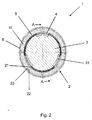
- FIG. 2 represents in the side view of the particularly advantageous running core carrier 1 with a deferred core 6 for an adhesive tape, wherein the core carrier 1 is seated on a winding shaft 3.
- a liner 5 made of metal.
- the bushing 5 is positively connected by (not shown) driver with the winding shaft 3, so that the bushing 5 rotates at the same speed as the winding shaft 3, so no slip is observed.
- three pressure hoses 31, which allow the targeted delivery of a radially outwardly acting, within a wide range freely selectable force.
- the pressure fluid hoses 31 are arranged in the axial direction in the winding shaft 3 and distributed uniformly over the circumference of the winding shaft 3.
- the pressure hoses 31 are in the winding shaft 3 milled grooves, so that when emptied pressure hoses 31, these are completely in the grooves.
- the torque of the winding shaft 3 is transmitted to the inner raceway of the clamping ring 11 under slip.
- FIG. 3 shows the core carrier 1 along with the winding shaft 3 after FIG. 2 in the lateral section along the line AA.
- the edges of the clamping ring 11 are slightly bevelled.
- the bushing 5 is shaped so that it serves as a spacer between the individual core carriers 1 on the winding shaft 3.
- it has on one side a disc-shaped collar 51 on the edge, whose diameter is equal to the outer diameter of the clamping ring 11.
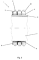
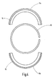
- FIG. 4 shows a further preferred embodiment of a core carrier 1 in an exploded view.
- the core carrier 1 comprises a clamping ring 11, which is composed of two approximately equal halves or ring portions 11 a, 11 b. In combination, both ring sections 11a, 11b provide a complete self-contained ring.
- the core carrier 1 comprises a snap ring 12 Spring steel.
- the snap ring 12 is in an inside groove 14 (see FIG. 5 ) of the clamping ring 11 and the ring sections 11 a, 11 b used.
- the snap ring 12 consists of a ring-shaped bent strand whose ends are arranged opposite and spaced from each other.
- the ring sections 11a, 11b have on both sides outer recesses 15, which are formed as continuous grooves.
- FIG. 5 shows a detailed perspective view of one of the ring portions 11a, 11b, which are identical.
- the snap ring 12 see FIG. 4 .
- FIG. 6 The view of FIG. 6 is essentially the same as FIG. 2 , wherein in the embodiment according to FIG. 6 the core carrier 1 according to FIG. 4 has been used.
- the clamping ring 11 from the FIG. 6 two interruption points 13a, 13b.
- both ring portions 11a, 11b abut against each other, whereas at the point of interruption 13a there is a gap between the two ring portions 11a, 11b.
- the size of the distance depends on the inner diameter of the core 6 or on the applied by the friction elements 4 radial forces.
- the remaining elements of the representation from the FIG. 6 correspond to those from the FIG. 2 ,
Landscapes
- Winding Of Webs (AREA)
- Storage Of Web-Like Or Filamentary Materials (AREA)
Applications Claiming Priority (2)
| Application Number | Priority Date | Filing Date | Title |
|---|---|---|---|
| DE102007045864 | 2007-09-25 | ||
| DE102008045109A DE102008045109A1 (de) | 2007-09-25 | 2008-09-01 | Selbstspannender Kernträger |
Publications (3)
| Publication Number | Publication Date |
|---|---|
| EP2042461A2 true EP2042461A2 (fr) | 2009-04-01 |
| EP2042461A3 EP2042461A3 (fr) | 2011-08-17 |
| EP2042461B1 EP2042461B1 (fr) | 2016-12-07 |
Family
ID=40130954
Family Applications (1)
| Application Number | Title | Priority Date | Filing Date |
|---|---|---|---|
| EP08163407.3A Not-in-force EP2042461B1 (fr) | 2007-09-25 | 2008-09-01 | Support de noyau autobloquant |
Country Status (1)
| Country | Link |
|---|---|
| EP (1) | EP2042461B1 (fr) |
Cited By (3)
| Publication number | Priority date | Publication date | Assignee | Title |
|---|---|---|---|---|
| ITVI20100265A1 (it) * | 2010-09-29 | 2012-03-30 | Svecom P E S R L | Albero espansibile perfezionato per l'avvolgimento di bobine multiple |
| CN106629164A (zh) * | 2017-02-09 | 2017-05-10 | 苏州威仕薄膜科技有限公司 | 一种贴膜卷绕管芯的张紧机构 |
| CN109727746A (zh) * | 2019-01-07 | 2019-05-07 | 中国科学院合肥物质科学研究院 | 一种超导限流器中超导线圈张紧调节装置 |
Citations (12)
| Publication number | Priority date | Publication date | Assignee | Title |
|---|---|---|---|---|
| DE1143074B (de) | 1958-11-13 | 1963-01-31 | Kampf Maschf Erwin | Wickelwelle |
| DE1237398B (de) | 1959-05-12 | 1967-03-23 | Kampf Maschf Erwin | Aufwickelwelle |
| DE1252032B (fr) | 1967-10-12 | |||
| DE2142286A1 (de) | 1970-08-28 | 1972-03-02 | The Robinson Waxed Paper Co Ltd , Bristol (Großbritannien) | Kernhulsenspannvorrichtung |
| US3817468A (en) | 1970-09-30 | 1974-06-18 | Agfa Gevaert Nv | Web tensioning device |
| US4220291A (en) | 1979-08-27 | 1980-09-02 | Papa Robert B | Apparatus for winding tape on cores |
| JPS6241144A (ja) | 1985-08-16 | 1987-02-23 | Shinko Seisakusho:Kk | テ−プ巻取装置 |
| JPH02132043A (ja) | 1988-11-14 | 1990-05-21 | Kataoka Mach Co Ltd | シート巻軸 |
| DE4309062A1 (de) | 1992-06-24 | 1994-01-13 | Beiersdorf Ag | Einzeln angetriebene Kernträger für Wickelwellen |
| DE19517225A1 (de) | 1995-05-11 | 1996-11-14 | Beiersdorf Ag | Wickelwelle |
| DE19517226A1 (de) | 1995-05-11 | 1996-11-14 | Beiersdorf Ag | Kernträger |
| DE10115297A1 (de) | 2001-03-28 | 2002-10-02 | Tesa Ag | Schnell extremspannender Kernträger |
Family Cites Families (1)
| Publication number | Priority date | Publication date | Assignee | Title |
|---|---|---|---|---|
| US3937412A (en) * | 1975-04-23 | 1976-02-10 | Damour Lawrence R | Expanding outer sleeve for a mandrel or chuck |
-
2008
- 2008-09-01 EP EP08163407.3A patent/EP2042461B1/fr not_active Not-in-force
Patent Citations (12)
| Publication number | Priority date | Publication date | Assignee | Title |
|---|---|---|---|---|
| DE1252032B (fr) | 1967-10-12 | |||
| DE1143074B (de) | 1958-11-13 | 1963-01-31 | Kampf Maschf Erwin | Wickelwelle |
| DE1237398B (de) | 1959-05-12 | 1967-03-23 | Kampf Maschf Erwin | Aufwickelwelle |
| DE2142286A1 (de) | 1970-08-28 | 1972-03-02 | The Robinson Waxed Paper Co Ltd , Bristol (Großbritannien) | Kernhulsenspannvorrichtung |
| US3817468A (en) | 1970-09-30 | 1974-06-18 | Agfa Gevaert Nv | Web tensioning device |
| US4220291A (en) | 1979-08-27 | 1980-09-02 | Papa Robert B | Apparatus for winding tape on cores |
| JPS6241144A (ja) | 1985-08-16 | 1987-02-23 | Shinko Seisakusho:Kk | テ−プ巻取装置 |
| JPH02132043A (ja) | 1988-11-14 | 1990-05-21 | Kataoka Mach Co Ltd | シート巻軸 |
| DE4309062A1 (de) | 1992-06-24 | 1994-01-13 | Beiersdorf Ag | Einzeln angetriebene Kernträger für Wickelwellen |
| DE19517225A1 (de) | 1995-05-11 | 1996-11-14 | Beiersdorf Ag | Wickelwelle |
| DE19517226A1 (de) | 1995-05-11 | 1996-11-14 | Beiersdorf Ag | Kernträger |
| DE10115297A1 (de) | 2001-03-28 | 2002-10-02 | Tesa Ag | Schnell extremspannender Kernträger |
Cited By (3)
| Publication number | Priority date | Publication date | Assignee | Title |
|---|---|---|---|---|
| ITVI20100265A1 (it) * | 2010-09-29 | 2012-03-30 | Svecom P E S R L | Albero espansibile perfezionato per l'avvolgimento di bobine multiple |
| CN106629164A (zh) * | 2017-02-09 | 2017-05-10 | 苏州威仕薄膜科技有限公司 | 一种贴膜卷绕管芯的张紧机构 |
| CN109727746A (zh) * | 2019-01-07 | 2019-05-07 | 中国科学院合肥物质科学研究院 | 一种超导限流器中超导线圈张紧调节装置 |
Also Published As
| Publication number | Publication date |
|---|---|
| EP2042461B1 (fr) | 2016-12-07 |
| EP2042461A3 (fr) | 2011-08-17 |
Similar Documents
| Publication | Publication Date | Title |
|---|---|---|
| DE2339754A1 (de) | Greifer zum erfassen eines zylindrischen gegenstandes | |
| DE102008001796B3 (de) | Spannkonus für einen Rollenwechsler | |
| DE2527690C3 (de) | Bandhaspel zum Auf- und Abwickeln von Metallbändern | |
| DE19738909A1 (de) | Aufweitbare Welle und diese aufweisende Bandwickelvorrichtung | |
| DE102015012521A1 (de) | Abwickelvorrichtung | |
| DE202017001904U1 (de) | Spreizwalze zum seitlichen Ausbreiten einer flächigen Materialbahn sowie Vorrichtung zum Handhaben von flächigen Materialbahnen | |
| DE69209297T2 (de) | Spreizbarer spanndorn | |
| DE202017102619U1 (de) | Aufspannvorrichtung für Etikettenrollen | |
| EP0863101B1 (fr) | Arbre d'enroulement avec accouplement à friction | |
| EP2042461B1 (fr) | Support de noyau autobloquant | |
| DE2024336A1 (de) | Kernzwischenstück | |
| DE3409145A1 (de) | Innenspannfutter | |
| WO2008145101A1 (fr) | Bobine pour une bande qui peut être enroulée et déroulée en spirale | |
| AT408236B (de) | Walze zur führung von bahnenförmigem material | |
| DE102008045109A1 (de) | Selbstspannender Kernträger | |
| DE102007010733B4 (de) | Einspannvorrichtung für eine Materialbahn | |
| EP0531285B1 (fr) | Tete de serrage pour cylindres de bobinage | |
| DE19517225C2 (de) | Wickelwelle | |
| DE10224839B4 (de) | Spanndorn | |
| DE102008043310A1 (de) | Breitstreckeinrichtung | |
| DE202006002658U1 (de) | Spanndorn für das Aufspannen einer Etikettenbandrolle o.dgl. | |
| DE10115297A1 (de) | Schnell extremspannender Kernträger | |
| DE19953370C1 (de) | Lagerung für eine Walze, insbesondere für die Druckwalze in einer Druckmaschine | |
| EP3307665A1 (fr) | Arbre d'enroulement destiné à recevoir au moins un mandrin d'enroulement | |
| DE102012213534B4 (de) | Wickelwelle, insbesondere für Rollenschneid- und Wickelmaschinen |
Legal Events
| Date | Code | Title | Description |
|---|---|---|---|
| PUAI | Public reference made under article 153(3) epc to a published international application that has entered the european phase |
Free format text: ORIGINAL CODE: 0009012 |
|
| AK | Designated contracting states |
Kind code of ref document: A2 Designated state(s): AT BE BG CH CY CZ DE DK EE ES FI FR GB GR HR HU IE IS IT LI LT LU LV MC MT NL NO PL PT RO SE SI SK TR |
|
| AX | Request for extension of the european patent |
Extension state: AL BA MK RS |
|
| RAP1 | Party data changed (applicant data changed or rights of an application transferred) |
Owner name: TESA SE |
|
| PUAL | Search report despatched |
Free format text: ORIGINAL CODE: 0009013 |
|
| AK | Designated contracting states |
Kind code of ref document: A3 Designated state(s): AT BE BG CH CY CZ DE DK EE ES FI FR GB GR HR HU IE IS IT LI LT LU LV MC MT NL NO PL PT RO SE SI SK TR |
|
| AX | Request for extension of the european patent |
Extension state: AL BA MK RS |
|
| RIC1 | Information provided on ipc code assigned before grant |
Ipc: B65H 49/36 20060101ALI20110712BHEP Ipc: B65H 75/24 20060101AFI20110712BHEP Ipc: B65H 54/54 20060101ALI20110712BHEP |
|
| 17P | Request for examination filed |
Effective date: 20120217 |
|
| AKX | Designation fees paid |
Designated state(s): AT BE BG CH CY CZ DE DK EE ES FI FR GB GR HR HU IE IS IT LI LT LU LV MC MT NL NO PL PT RO SE SI SK TR |
|
| RAP1 | Party data changed (applicant data changed or rights of an application transferred) |
Owner name: TESA SE |
|
| GRAP | Despatch of communication of intention to grant a patent |
Free format text: ORIGINAL CODE: EPIDOSNIGR1 |
|
| INTG | Intention to grant announced |
Effective date: 20160708 |
|
| GRAS | Grant fee paid |
Free format text: ORIGINAL CODE: EPIDOSNIGR3 |
|
| GRAA | (expected) grant |
Free format text: ORIGINAL CODE: 0009210 |
|
| STAA | Information on the status of an ep patent application or granted ep patent |
Free format text: STATUS: THE PATENT HAS BEEN GRANTED |
|
| AK | Designated contracting states |
Kind code of ref document: B1 Designated state(s): AT BE BG CH CY CZ DE DK EE ES FI FR GB GR HR HU IE IS IT LI LT LU LV MC MT NL NO PL PT RO SE SI SK TR |
|
| REG | Reference to a national code |
Ref country code: GB Ref legal event code: FG4D Free format text: NOT ENGLISH |
|
| REG | Reference to a national code |
Ref country code: CH Ref legal event code: EP Ref country code: AT Ref legal event code: REF Ref document number: 851500 Country of ref document: AT Kind code of ref document: T Effective date: 20161215 |
|
| REG | Reference to a national code |
Ref country code: IE Ref legal event code: FG4D Free format text: LANGUAGE OF EP DOCUMENT: GERMAN |
|
| REG | Reference to a national code |
Ref country code: DE Ref legal event code: R096 Ref document number: 502008014861 Country of ref document: DE |
|
| PG25 | Lapsed in a contracting state [announced via postgrant information from national office to epo] |
Ref country code: LV Free format text: LAPSE BECAUSE OF FAILURE TO SUBMIT A TRANSLATION OF THE DESCRIPTION OR TO PAY THE FEE WITHIN THE PRESCRIBED TIME-LIMIT Effective date: 20161207 |
|
| REG | Reference to a national code |
Ref country code: LT Ref legal event code: MG4D |
|
| REG | Reference to a national code |
Ref country code: NL Ref legal event code: MP Effective date: 20161207 |
|
| PG25 | Lapsed in a contracting state [announced via postgrant information from national office to epo] |
Ref country code: GR Free format text: LAPSE BECAUSE OF FAILURE TO SUBMIT A TRANSLATION OF THE DESCRIPTION OR TO PAY THE FEE WITHIN THE PRESCRIBED TIME-LIMIT Effective date: 20170308 Ref country code: SE Free format text: LAPSE BECAUSE OF FAILURE TO SUBMIT A TRANSLATION OF THE DESCRIPTION OR TO PAY THE FEE WITHIN THE PRESCRIBED TIME-LIMIT Effective date: 20161207 Ref country code: NO Free format text: LAPSE BECAUSE OF FAILURE TO SUBMIT A TRANSLATION OF THE DESCRIPTION OR TO PAY THE FEE WITHIN THE PRESCRIBED TIME-LIMIT Effective date: 20170307 Ref country code: LT Free format text: LAPSE BECAUSE OF FAILURE TO SUBMIT A TRANSLATION OF THE DESCRIPTION OR TO PAY THE FEE WITHIN THE PRESCRIBED TIME-LIMIT Effective date: 20161207 |
|
| PG25 | Lapsed in a contracting state [announced via postgrant information from national office to epo] |
Ref country code: FI Free format text: LAPSE BECAUSE OF FAILURE TO SUBMIT A TRANSLATION OF THE DESCRIPTION OR TO PAY THE FEE WITHIN THE PRESCRIBED TIME-LIMIT Effective date: 20161207 Ref country code: HR Free format text: LAPSE BECAUSE OF FAILURE TO SUBMIT A TRANSLATION OF THE DESCRIPTION OR TO PAY THE FEE WITHIN THE PRESCRIBED TIME-LIMIT Effective date: 20161207 |
|
| REG | Reference to a national code |
Ref country code: ES Ref legal event code: FG2A Ref document number: 2619625 Country of ref document: ES Kind code of ref document: T3 Effective date: 20170626 |
|
| PG25 | Lapsed in a contracting state [announced via postgrant information from national office to epo] |
Ref country code: NL Free format text: LAPSE BECAUSE OF FAILURE TO SUBMIT A TRANSLATION OF THE DESCRIPTION OR TO PAY THE FEE WITHIN THE PRESCRIBED TIME-LIMIT Effective date: 20161207 |
|
| PG25 | Lapsed in a contracting state [announced via postgrant information from national office to epo] |
Ref country code: IS Free format text: LAPSE BECAUSE OF FAILURE TO SUBMIT A TRANSLATION OF THE DESCRIPTION OR TO PAY THE FEE WITHIN THE PRESCRIBED TIME-LIMIT Effective date: 20170407 Ref country code: EE Free format text: LAPSE BECAUSE OF FAILURE TO SUBMIT A TRANSLATION OF THE DESCRIPTION OR TO PAY THE FEE WITHIN THE PRESCRIBED TIME-LIMIT Effective date: 20161207 Ref country code: RO Free format text: LAPSE BECAUSE OF FAILURE TO SUBMIT A TRANSLATION OF THE DESCRIPTION OR TO PAY THE FEE WITHIN THE PRESCRIBED TIME-LIMIT Effective date: 20161207 Ref country code: SK Free format text: LAPSE BECAUSE OF FAILURE TO SUBMIT A TRANSLATION OF THE DESCRIPTION OR TO PAY THE FEE WITHIN THE PRESCRIBED TIME-LIMIT Effective date: 20161207 Ref country code: CZ Free format text: LAPSE BECAUSE OF FAILURE TO SUBMIT A TRANSLATION OF THE DESCRIPTION OR TO PAY THE FEE WITHIN THE PRESCRIBED TIME-LIMIT Effective date: 20161207 |
|
| PG25 | Lapsed in a contracting state [announced via postgrant information from national office to epo] |
Ref country code: PT Free format text: LAPSE BECAUSE OF FAILURE TO SUBMIT A TRANSLATION OF THE DESCRIPTION OR TO PAY THE FEE WITHIN THE PRESCRIBED TIME-LIMIT Effective date: 20170407 Ref country code: PL Free format text: LAPSE BECAUSE OF FAILURE TO SUBMIT A TRANSLATION OF THE DESCRIPTION OR TO PAY THE FEE WITHIN THE PRESCRIBED TIME-LIMIT Effective date: 20161207 Ref country code: BG Free format text: LAPSE BECAUSE OF FAILURE TO SUBMIT A TRANSLATION OF THE DESCRIPTION OR TO PAY THE FEE WITHIN THE PRESCRIBED TIME-LIMIT Effective date: 20170307 |
|
| REG | Reference to a national code |
Ref country code: DE Ref legal event code: R097 Ref document number: 502008014861 Country of ref document: DE |
|
| REG | Reference to a national code |
Ref country code: FR Ref legal event code: PLFP Year of fee payment: 10 |
|
| PLBE | No opposition filed within time limit |
Free format text: ORIGINAL CODE: 0009261 |
|
| STAA | Information on the status of an ep patent application or granted ep patent |
Free format text: STATUS: NO OPPOSITION FILED WITHIN TIME LIMIT |
|
| 26N | No opposition filed |
Effective date: 20170908 |
|
| PG25 | Lapsed in a contracting state [announced via postgrant information from national office to epo] |
Ref country code: SI Free format text: LAPSE BECAUSE OF FAILURE TO SUBMIT A TRANSLATION OF THE DESCRIPTION OR TO PAY THE FEE WITHIN THE PRESCRIBED TIME-LIMIT Effective date: 20161207 Ref country code: DK Free format text: LAPSE BECAUSE OF FAILURE TO SUBMIT A TRANSLATION OF THE DESCRIPTION OR TO PAY THE FEE WITHIN THE PRESCRIBED TIME-LIMIT Effective date: 20161207 |
|
| REG | Reference to a national code |
Ref country code: CH Ref legal event code: PL |
|
| PG25 | Lapsed in a contracting state [announced via postgrant information from national office to epo] |
Ref country code: MC Free format text: LAPSE BECAUSE OF FAILURE TO SUBMIT A TRANSLATION OF THE DESCRIPTION OR TO PAY THE FEE WITHIN THE PRESCRIBED TIME-LIMIT Effective date: 20161207 |
|
| REG | Reference to a national code |
Ref country code: IE Ref legal event code: MM4A |
|
| REG | Reference to a national code |
Ref country code: BE Ref legal event code: MM Effective date: 20170930 |
|
| PG25 | Lapsed in a contracting state [announced via postgrant information from national office to epo] |
Ref country code: LU Free format text: LAPSE BECAUSE OF NON-PAYMENT OF DUE FEES Effective date: 20170901 |
|
| PG25 | Lapsed in a contracting state [announced via postgrant information from national office to epo] |
Ref country code: LI Free format text: LAPSE BECAUSE OF NON-PAYMENT OF DUE FEES Effective date: 20170930 Ref country code: CH Free format text: LAPSE BECAUSE OF NON-PAYMENT OF DUE FEES Effective date: 20170930 Ref country code: IE Free format text: LAPSE BECAUSE OF NON-PAYMENT OF DUE FEES Effective date: 20170901 |
|
| PG25 | Lapsed in a contracting state [announced via postgrant information from national office to epo] |
Ref country code: BE Free format text: LAPSE BECAUSE OF NON-PAYMENT OF DUE FEES Effective date: 20170930 |
|
| REG | Reference to a national code |
Ref country code: FR Ref legal event code: PLFP Year of fee payment: 11 |
|
| PG25 | Lapsed in a contracting state [announced via postgrant information from national office to epo] |
Ref country code: MT Free format text: LAPSE BECAUSE OF FAILURE TO SUBMIT A TRANSLATION OF THE DESCRIPTION OR TO PAY THE FEE WITHIN THE PRESCRIBED TIME-LIMIT Effective date: 20161207 |
|
| PGFP | Annual fee paid to national office [announced via postgrant information from national office to epo] |
Ref country code: IT Payment date: 20180925 Year of fee payment: 11 |
|
| REG | Reference to a national code |
Ref country code: AT Ref legal event code: MM01 Ref document number: 851500 Country of ref document: AT Kind code of ref document: T Effective date: 20170901 |
|
| PGFP | Annual fee paid to national office [announced via postgrant information from national office to epo] |
Ref country code: GB Payment date: 20180919 Year of fee payment: 11 |
|
| PG25 | Lapsed in a contracting state [announced via postgrant information from national office to epo] |
Ref country code: AT Free format text: LAPSE BECAUSE OF NON-PAYMENT OF DUE FEES Effective date: 20170901 |
|
| PGFP | Annual fee paid to national office [announced via postgrant information from national office to epo] |
Ref country code: ES Payment date: 20181022 Year of fee payment: 11 |
|
| PG25 | Lapsed in a contracting state [announced via postgrant information from national office to epo] |
Ref country code: HU Free format text: LAPSE BECAUSE OF FAILURE TO SUBMIT A TRANSLATION OF THE DESCRIPTION OR TO PAY THE FEE WITHIN THE PRESCRIBED TIME-LIMIT; INVALID AB INITIO Effective date: 20080901 |
|
| PG25 | Lapsed in a contracting state [announced via postgrant information from national office to epo] |
Ref country code: CY Free format text: LAPSE BECAUSE OF NON-PAYMENT OF DUE FEES Effective date: 20161207 |
|
| PG25 | Lapsed in a contracting state [announced via postgrant information from national office to epo] |
Ref country code: TR Free format text: LAPSE BECAUSE OF FAILURE TO SUBMIT A TRANSLATION OF THE DESCRIPTION OR TO PAY THE FEE WITHIN THE PRESCRIBED TIME-LIMIT Effective date: 20161207 |
|
| PG25 | Lapsed in a contracting state [announced via postgrant information from national office to epo] |
Ref country code: IT Free format text: LAPSE BECAUSE OF NON-PAYMENT OF DUE FEES Effective date: 20190901 |
|
| GBPC | Gb: european patent ceased through non-payment of renewal fee |
Effective date: 20190901 |
|
| PG25 | Lapsed in a contracting state [announced via postgrant information from national office to epo] |
Ref country code: FR Free format text: LAPSE BECAUSE OF NON-PAYMENT OF DUE FEES Effective date: 20190930 Ref country code: GB Free format text: LAPSE BECAUSE OF NON-PAYMENT OF DUE FEES Effective date: 20190901 |
|
| REG | Reference to a national code |
Ref country code: ES Ref legal event code: FD2A Effective date: 20210127 |
|
| PG25 | Lapsed in a contracting state [announced via postgrant information from national office to epo] |
Ref country code: ES Free format text: LAPSE BECAUSE OF NON-PAYMENT OF DUE FEES Effective date: 20190902 |
|
| PGFP | Annual fee paid to national office [announced via postgrant information from national office to epo] |
Ref country code: DE Payment date: 20230920 Year of fee payment: 16 |
|
| REG | Reference to a national code |
Ref country code: DE Ref legal event code: R119 Ref document number: 502008014861 Country of ref document: DE |
|
| PG25 | Lapsed in a contracting state [announced via postgrant information from national office to epo] |
Ref country code: DE Free format text: LAPSE BECAUSE OF NON-PAYMENT OF DUE FEES Effective date: 20250401 |