EP2042644A1 - Sèche-linge - Google Patents
Sèche-linge Download PDFInfo
- Publication number
- EP2042644A1 EP2042644A1 EP08016569A EP08016569A EP2042644A1 EP 2042644 A1 EP2042644 A1 EP 2042644A1 EP 08016569 A EP08016569 A EP 08016569A EP 08016569 A EP08016569 A EP 08016569A EP 2042644 A1 EP2042644 A1 EP 2042644A1
- Authority
- EP
- European Patent Office
- Prior art keywords
- dryer
- drum
- supply device
- hose
- dryer according
- Prior art date
- Legal status (The legal status is an assumption and is not a legal conclusion. Google has not performed a legal analysis and makes no representation as to the accuracy of the status listed.)
- Granted
Links
Images


Classifications
-
- D—TEXTILES; PAPER
- D06—TREATMENT OF TEXTILES OR THE LIKE; LAUNDERING; FLEXIBLE MATERIALS NOT OTHERWISE PROVIDED FOR
- D06F—LAUNDERING, DRYING, IRONING, PRESSING OR FOLDING TEXTILE ARTICLES
- D06F58/00—Domestic laundry dryers
- D06F58/20—General details of domestic laundry dryers
- D06F58/203—Laundry conditioning arrangements
Definitions
- the present invention relates to a dryer, and more particularly to a laundry dryer capable of effectively removing creases or rumples from an object to be dried, for example, laundry, and effectively removing odor from the laundry.
- a dryer is a home appliance used to dry laundry completely washed, namely, an object to be dried, using hot air.
- a laundry dryer includes a drum for accommodating an object to be dried therein, and a drive source for driving the drum, a heater for heating air introduced into the drum, and a blower unit for sucking air into the drum or outwardly discharging air from the drum.
- Dryers may be classified into an electric type and a gas type in accordance with the type of the system for heating air, namely, the type of the heater.
- the electric type dryer heats air, using heat generated from an electrical resistance.
- the gas type dryer heats air, using heat generated in accordance with the combustion of gas.
- Dryers may also be classified into an exhaustion type and a condensation type.
- the condensation type dryer air, which has become humid after being heat-exchanged with an object to be dried, is circulated without being outwardly discharged. The air is heat-exchanged with ambient air through a separate condenser. In accordance with this heat exchange, condensed water is generated, and is then outwardly discharged.
- air which has become humid after being heat-exchanged with an object to be dried, is directly discharged to the outside of the dryer.
- Dryers may also be classified into a top loading type and a front loading type in accordance with the object loading type.
- the top loading type dryer an object to be dried is loaded into the dryer through the top of the dryer.
- the front loading type dryer an object to be dried is loaded into the dryer through the front side of the dryer.
- creases may be formed at the clothes.
- the present invention is directed to a dryer that substantially obviates one or more problems due to limitations and disadvantages of the related art.
- An object of the present invention is to provide a dryer capable of avoiding the formation of creases on an object completely dried and removing creases formed on the object.
- Another object of the present invention is to provide a dryer, which can be easily manufactured, and can be easily serviced, so that it can be conveniently used.
- Another object of the present invention is to provide a dryer capable of preventing occurrence of an accident.
- Another object of the present invention is to provide a dryer capable of supplying steam or moisture mist, to perform, in addition to a general drying function, various additional functions.
- Another object of the present invention is to provide a dryer, which can obviate the above-mentioned problems without a considerable change in the outer structure of the conventional dryer, and an increase in the distance between the front and rear walls of the dryer, so that the dryer can be easily installed.
- a dryer comprises: a drum for accommodating an object to be dried; a rear supporter for covering a rear side of the drum; a substance supply device having an end arranged at the rear supporter, to supply a water-based substance to an interior of the drum; and a rear plate formed to constitute a rear wall of the dryer while partially exposing the substance supply device.
- a dryer comprising a drum for accommodating an object to be dried, a rear supporter for covering a rear side of the drum, and a rear plate constituting a rear wall of the dryer further comprises a substance supply device having an end arranged at the rear supporter, to supply a water-based substance to an interior of the drum, wherein the rear plate is formed to partially expose the substance supply device.
- the rear plate may comprise a cutout formed to partially expose the substance supply device.
- the dryer may further comprise a damage preventing member provided at the cutout, to prevent the substance supply device from being damaged by the cutout. This is because a sharp edge may be formed at the cutout, so that the substance supply device may be damaged by the sharp edge.
- the damage preventing member may also perform a function to prevent a user, a worker who manufactures the dryer or a service man from being injured by the sharp edge.
- the cutout may be formed at an upper portion of the rear plate.
- the rear plate may further comprise a coupling portion coupled to a top plate constituting a top wall of the dryer or to the rear supporter, an extension extending rearwardly from the coupling portion, to form a rearmost surface of the dryer, and a connecting portion connecting the coupling portion and the extension.
- the cutout may be formed through the connecting portion.
- the cutout may be formed to extend along the coupling portion and the connecting portion.
- the substance supply device may comprise a hose providing a substance flowing passage.
- the hose may be connected to the rear plate.
- the cutout may outwardly expose a portion of the hose connected to the rear plate.
- the substance supply device may further comprise a nozzle provided at an end of the hose. The nozzle may be coupled to the rear supporter.
- the water-based substance may comprise mist sprayed under a water pressure.
- the water-based substance may comprise steam.
- the dryer may further comprise a steam generator arranged inwardly of the rear supporter, to generate steam.
- the substance supply device may comprise a hose connected to the steam generator at one end of the substance supply device.
- the hose may extend rearwardly beyond the rear supporter at the other end of the substance supply device.
- the dryer may further comprise a cover for covering an exposed portion of the substance supply device, to selectively open/close the exposed portion.
- the cover may be provided at the rear plate.
- the cover may comprise an opening/closing member pivotally movable between an opened position and a closed position, and a frame coupled to the rear plate, to support the opening/closing member such that the opening/closing member is pivotally movable.
- the cover may be arranged such that, when the cover closes the exposed portion of the substance supply device, a rearmost surface of the cover is positioned inwardly of a rearmost surface of the rear plate.
- the dryer may further comprise a refractory material provided at an inner surface of the cover.
- the rear plate may comprise a cutout formed to partially expose the substance supply device.
- the cover may comprise a damage preventing member provided at the cutout, to prevent the substance supply device from being damaged by the cutout.
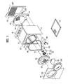
- FIG. 1 is an exploded perspective view illustrating a dryer according to an exemplary embodiment of the present invention
- FIG. 2 is a sectional view of the dryer shown in FIG. 1 ;
- FIG. 3 is a view illustrating a steam generator installed in the dryer shown in FIG. 1 ;
- FIG. 4 is an enlarged view of a rear upper portion of the dryer shown in FIG. 1 ;
- FIG. 5 is a perspective view illustrating a cover provided at the dryer in accordance with an exemplary embodiment of the present invention
- FIG. 6 is an enlarged view illustrating a state in which the cover shown in FIG. 5 is coupled to the dryer.
- FIG. 7 is an enlarged view illustrating another embodiment of the cover shown in FIG. 5 .
- FIGs. 1 and 2 a basic configuration of a dryer according to an exemplary embodiment of the present invention will be described with reference to FIGs. 1 and 2 .
- the dryer As shown in FIGs. 1 and 2 , the dryer according to the illustrated embodiment of the present invention includes a cabinet 10 forming an outer appearance of the dryer, and a drum 20 rotatably installed in the cabinet 10.
- the dryer also includes a motor 70 and a belt 68 to drive the drum 20.
- An air heater 90 is arranged in the cabinet 10 at a desired position, to heat air, and thus to generate hot air.
- a hot air supply duct 44 is also arranged in the cabinet 10, to supply the hot air generated by the air heater 90 to the drum 20.
- an exhaust duct 80 for exhausting humid air heat-exchanged with objects to be dried in the drum 20, and a blower unit 60 for sucking the humid air are also arranged.
- an exhaustion type dryer is described in this embodiment, for the convenience of description, the present invention is not limited thereto.
- the present invention may also be applied to a condensation type dryer, in which a separate condensing duct (not shown) is provided to condense humid air heat-exchanged with an object to be dried, and thus to again supply dry air to a drum.
- the cabinet 10 which forms the outer appearance of the dryer, includes a base 12 forming a bottom wall, a pair of side plates 14 extending vertically from the base 12, front and rear plates 16 and 18 respectively mounted to front and rear ends of the base 12 where the side plates 14 are not arranged, and a top plate 17 disposed on the upper ends of the side plates 14.
- a control panel 19, which includes operating switches, a display, etc., may be arranged on the top plate 17 or front plate 16. In this embodiment, the control panel 19 is illustrated as being arranged on the top plate 17.
- a louver 182 is provided at the rear plate 18, to introduce ambient air into the cabinet 10.
- An exhaust hole 184 is also provided at the rear plate 18, as a passage for finally discharging air from the drum 20 to the outside of the drum 20. It is preferred that lifters 22 be installed in the drum 20, to turn over laundry in the drum 20, and thus to achieve an enhancement in drying efficiency.
- a front supporter 30 is arranged in rear of the front plate 16.
- a rear supporter 40 is arranged in front of the rear plate 18.
- the drum 20 is rotatably supported between the front supporter 30 and the rear supporter 40.
- Sealing members are fitted between the front supporter 30 and the drum 20 and between the rear supporter 40 and the drum 20, respectively, to prevent water leakage.
- the front supporter 30 may have, at a central portion thereof, an opening, through which an object to be dried can be loaded/unloaded.
- the rear supporter 40 completely covers the rear side of the drum 20, to prevent an object to be dried from being loaded/unloaded through the rear side of the drum 20.
- the front supporter 30 and rear supporter 40 close the front and rear ends of the drum 20, to define a drying chamber in the drum 20.
- the front supporter 30 and rear supporter 40 also function to support the front and rear ends of the drum 20.
- An opening 162 is formed through the front plate 16, to communicate the drum 20 with the outside of the dryer.
- the opening 162 is selectively opened or closed by the door 164.
- a lint duct 50 which is a passage for outwardly discharging air from the drum 20, is connected to the front supporter 30.
- a lint filter 52 is installed in the lint duct 50.
- blower unit 60 One side of the blower unit 60 is connected to the lint duct 50. The other side of the blower unit 60 is connected to the exhaust duct 80.
- the exhaust duct 80 communicates with an exhaust hole 184 provided at the rear plate 18.
- the blower unit 60 includes a blower 62, and a blower housing 64.
- the blower 62 is connected to the motor 70, which drives the drum 20.
- the blower 62 may be driven by a motor (not shown) separate from the motor 70.
- An inlet port 42 which is constituted by a plurality of through holes, is formed through the rear supporter 40.
- a hot air supply duct 44 is connected to the inlet port 42.
- the hot air supply duct 44 communicates with the drum 20 via the inlet port 42 of the rear supporter 40, to function as a passage for supplying hot air to the drum 20.
- the air heater 90 is installed at a certain position in the hot air supply duct 44.
- the dryer according to the present invention includes a substance supply device for supplying a water-based substance to the interior of the drum 20.
- the water-based substance may be steam generated as water is heated.
- the substance supply device may be a steam supply device, which supplies steam.
- the dryer dries an object to be dried, using hot air.
- creases or rumples may be formed on the object as the drying operation proceeds. For this reason, an ironing operation may be required after the object is completely dried.
- it is possible to reduce or eliminate the formation of such creases or rumples by supplying steam to the object during the drying operation. That is, when steam is supplied to a creased or rumpled portion of the object, to supply moisture to the creased or rumpled object portion, and the object is then dried using hot air, creases or rumples from the creased or rumpled object portion are removed as the moisture is evaporated by the hot air. Accordingly, it may be preferred that the supply of the steam be initiated after the object is dried to some degree in accordance with the drying operation.
- steam has the form of hot fine water particles having a particle size of several microns. Accordingly, such steam supplies moisture and high-temperature heat to the object to be dried, thereby removing odor particles from the object. Thus, it is possible to effectively remove odor through a dryer using steam.
- steam is a medium for supplying moisture and high-temperature heat to the object to be dried. Since steam has the form of very fine particles, as described above, it can effectively penetrate the object. Accordingly, moisture can be uniformly absorbed into the overall portion of the object. In other words, it is possible to effectively prevent moisture from being excessively absorbed into only a particular portion of the object.
- the dryer can have, in addition to a simple drying function, additional functions such as removal or prevention of creases, removal of odor, removal of static electricity, and addition of moisture to laundry in an amount desired to achieve an easy ironing operation.
- additional functions such as removal or prevention of creases, removal of odor, removal of static electricity, and addition of moisture to laundry in an amount desired to achieve an easy ironing operation.
- the water-based substance may be water.
- the water-based substance may be water supplied to the interior of the drum.
- the water-based substance is water
- the substance supply device may be a mist supply device, which supplies mist.
- mist can uniformly supply a certain amount of moisture to the object to be dried, without completely wetting the object.
- the steam generator which generates steam, may be dispensed with.
- the temperature of the mist is not high because the mist is formed as water of ambient temperature is sprayed. Also, the particle size of the mist may be several ten microns. For this reason, the mist may be supplied to a particular portion of the object, without being uniformly supplied to the overall portion of the object, as compared to steam.
- the dryer includes an air supplier (the hot air heater, blower unit, etc.) to supply hot air or cold air to the interior of the drum.
- the air supplier operates to supply hot air to the drum when the mist is supplied to the drum.
- the mist is heated, so that it is partially vaporized.
- the particle size of the mist is reduced.
- moisture can be uniformly and deeply absorbed into the object.
- the position of a nozzle, from which the mist is sprayed be approximate to the position of the inlet port 42, through which hot air is introduced into the drum.
- the nozzle which supplies fine moisture to the interior of the drum, may be provided at the rear supporter 40 such that the nozzle is arranged near the inlet port 42.
- the nozzle may be arranged in the hot air supply duct 44.
- the mist may be supplied to the interior of the drum through the inlet port 42, together with hot air, after being heated in the hot air supply duct 44.
- the water-based substance may be an additive for adding fragrance to the object to be dried.
- the additive it is preferred that the additive be supplied to the drum in the form of mist, as in the case of water.
- a steam generator 200 generates steam. Water is supplied to the steam generator 200 which, in turn, heats the supplied water, to generate steam.
- the steam generator 200 may receive water supplied from a water supplier connected to an external water tap.
- the steam generator 200 may receive water from a tank (not shown) equipped in the dryer via a water supplier. In the latter case, a pump (not shown) for pumping water may further be provided.
- the steam generated from the steam generator 200 is supplied to the drum 20 via the substance supply device.
- the steam generator 200 includes a water tank 210 for containing water therein, and a heater 240 mounted in the water tank 210.
- the steam generator 200 is connected with a water supply hose 220 to supply water to the steam generator 200.
- the steam generator 200 is also connected with a steam hose 230 to discharge steam from the steam generator 200.
- a nozzle 250 having a certain shape is arranged at an end of the steam hose 230 opposite to the steam generator 200.
- the water supply hose 220 may be connected to an external water supply source such as a city water tap, at an end of the water supply hose 220 opposite to the steam generator 200.
- the end of the steam hose 230 opposite to the steam generator 200 or the nozzle 250 is disposed at a desired position in the drum 20, to spray steam into the interior of the drum 20.
- the water supply hose 220 may be connected to a tank (not shown), which is mounted in the cabinet 10, to store a certain amount of water, without being connected to an external water supply source such as a city water tap.
- the water supply hose 220 functions as the water supplier, whereas the steam hose 230 and nozzle 250 function as the substance supply device.
- the nozzle 250 it may be possible to supply steam by arranging the end of the steam hose 230 opposite to the steam generator 200 in the interior of the drum 20. However, it is preferred that the nozzle 250 be provided at the end of the steam hose 230 because the nozzle 250 functions to provide an effective steam spraying angle and an effective steam distribution in the drum. Of course, the nozzle 250 can be integrated with the steam hose 230.
- the water supplier is illustrated as being arranged at one side of the steam generator 200, and the substance supply device is illustrated as being arranged at the other side of the steam generator 200, in the case of FIG. 3 , the present invention is not limited thereto.
- the water supplier and substance supply device may be arranged at the same side of the steam generator 200.
- the installation positions of the water supplier and substance supply device may be appropriately changed.
- the steam generator 200 may have a configuration different from the above-described configuration.
- the steam generator 200 may be configured to heat water flowing through a pipe-shaped housing (not shown), for the generation of steam, without heating water contained in the water tank 210.
- the former steam generator is referred to as a "barrel type steam generator”
- the latter steam generator is referred to as a "pipe type steam generator”.
- the pipe type steam generator can greatly reduce the time taken to generate steam, as compared to the barrel type steam generator, because the pipe type steam generator generates steam by rapidly heating water. In the pipe type steam generator, however, there may be a problem in that hot water other than steam may be supplied to the interior of the drum. As compared to the pipe type steam generator, the barrel type steam generator has an advantage in that it is possible to stably supply steam to the interior of the drum.
- the steam generator 200 be arranged above the drum 20, namely, between the top of the drum 20 and the top plate 17. This is because the space defined between the drum 20 and the top plate 17 corresponds to a relatively-empty space portion of the interior of the cabinet 10, so that superior space utility can be obtained when the steam generator 200 is arranged between the drum 20 and the top plate 17. Where the steam generator 200 is arranged in the above-described space, there is an advantage in terms of service because, when the steam generator 200 is out of order, it is possible to repair the steam generator 200 after separating the top cover 17.
- the tank (not shown) for storing water, the pump (not shown), etc. may be arranged at the same position as the steam generator 200.
- the hose 230 which constitutes the substance supply device, extend rearwardly beyond the rear supporter 40.
- the hose 230 may be a steam hose.
- the hose 230 may be a typical water hose.
- the material of the hose 230 may be varied in accordance with the kind of the substance flowing through the hose 230.
- the nozzle 250 be mounted to the rear supporter 40.
- the hose 230 may be connected to the rear supporter 40 via the nozzle 250.
- the nozzle 250 is mounted to the rear supporter 50, it is preferred that the nozzle 250 be directed to a central portion of the drum 20. This will be described in detail later.
- the rear plate 18, which forms the rear wall of the cabinet 10 be configured to expose at least a portion of the substance supply device.
- the rear plate 18 may be formed with a cutout 180, as shown in FIG. 4 .
- the cutout 180 is formed to expose the hose 230 and nozzle 250 constituting the substance supply device. That is, it is preferred that the cutout 180 be formed at a position corresponding to a region where the hose 230 and nozzle 250 are arranged. Accordingly, where the nozzle 250 is arranged at an upper portion of the drum while being supported by the rear support 40, it is preferred that the cutout 180 be formed at an upper portion of the rear plate 19.
- the reason why the cutout 180 is formed at an upper portion of the rear plate 18 is that, when a failure occurs in the steam hose 230 or nozzle 250, it is possible to easily repair the failed steam hose 230 or nozzle 250 through the cutout 180. That is, an enhancement in serviceability is achieved. In other words, it is possible to achieve easy service without a separation of the rear plate 18.
- the mounting of the nozzle 250 to the rear supporter 40 can be carried out in a region other than the interior of the drum, for example, at the rear side of the rear supporter 40.
- the mounting process is very difficult due to the length of the drum.
- the rear supporter 40 is assembled to the drum 20 under the condition in which the nozzle 250 has been mounted to the rear supporter 40, the hose 230 may be damaged, and the assembly process may be difficult due to the hose 230.
- the cutout 180 is normally in a covered state, and is selectively exposed, if necessary. This is because the user may be injured by the cutout 180 of the rear plate 18. Also, the user may get burned when he comes into contact with the hose 230, through which hot steam flows. In addition, when the hose 230 is in an outwardly-exposed state, it may be damaged by external environments.
- the dryer according to the present invention include a cover 300 for covering the cutout 180 such that the cutout 180 can be selectively opened, in order to achieve an enhancement in serviceability and to prevent the user from being subjected to an accident.
- the cover 300 is separably coupled to the rear plate 18.
- the cover 300 includes a frame 310 having a shape corresponding to the shape of the cutout 180.
- An opening 311 is formed through the frame 310.
- the cover 300 also includes an opening/closing member 320 coupled to the frame 310 by a hinge 313, to open/close the opening 311 of the frame 310.
- the hinge 313 functions to pivotally couple the frame 310 and opening/closing member 320.
- the hinge 313 may be provided by forming a connecting portion of the frame 310 and opening/closing member 320 such that the connecting portion is thinner than other portions, to perform a hinge function.
- the cover 300 is made of a synthetic resin different from the material of the rear plate 18.
- the cover 300 be made of polypropylene exhibiting excellent properties in terms of rigidity, impact resistance, and electrical characteristics. Since the cutout 180 is covered by the cover 300, as described above, it is possible to prevent the user or service man from getting burned as he comes into contact with the steam hose 230. It is also possible to prevent the user or service man from being injured by a sharp portion of the cutout 180.
- a plurality of hooks 312 may be formed at the frame 310 of the cover 300, in order to separably couple the cover 300 to the rear plate 18, and to easily achieve the coupling of the cover 300 to the rear plate 18.
- Each hook 312 extends from a periphery of the frame 310 while having an inverted-L shape, in order to allow the cutout edge of the rear plate 18 to be fitted between the frame 310 and the hook 312.
- the cover 300 can be firmly coupled to the rear plate 18.
- the cover 300 may be separably coupled to the rear plate 18 by typical means such as a screw. Since the frame 310 has elasticity as it is made of polypropylene, the hooks 311 can be easily engaged with the cutout edge of the rear plate 18 in accordance with an elastic deformation of the frame 310.
- the frame 310 and opening/closing member 320 be integrally formed at one side thereof such that the opening/closing member 320 can open/close the opening 311.
- a plurality of engagement portions 321 are formed at the opening/closing member 320, which opens/closes the opening 311.
- the opening/closing member 320 may be temporarily coupled to the frame 310 in a state of closing the opening 311.
- a protrusion 325 is formed at a portion of the periphery of the opening/closing member 320.
- a fastening hole 326 is formed through the protrusion 325, to enable the opening/closing member 320 to be completely coupled to the rear plate 18 by a fastening member.
- a fastening groove 181 is formed on the rear plate 18 at a position corresponding to the fastening hole 326 when the opening/closing member 320 closes the opening 311 of the frame 310.
- a refractory material 400 is provided at an inner surface of the opening/closing member 320, to prevent the safety member, namely, the cover 300, from being burned.
- the reason why the refractory material 400 is provided is that, when an inflammable material is introduced into the drum 20 through carelessness of the user, it may be ignited by hot air supplied to the drum 20, so that a fire may break out in the drum 20. In this case, the refractory material 400 prevents the fire from the drum 20 from being propagated to the outside of the cabinet 10 after burning the steam hose 230 and cover 300.
- the cabinet 120 is made of a metal material
- the steam hose 230 and cover 300 are made of a molded rubber or plastic product. For this reason, the fire broken out in the drum 20 may be easily propagated via the steam hose 230 and cover 300.
- any material may be used, as long as it can prevent the fire broken out in the cabinet 20 from being propagated to the outside of the cabinet 10.
- a ceramic material may be bonded to the inner surface of the opening/closing member 320.
- a refractory paint may be applied to the inner surface of the opening/closing member 320.
- FIG. 6 illustrates a state in which the cover 300 according to the present invention is mounted to the rear plate 18 around the cutout 180, and the opening/closing member 320 of the cover 300 is fastened to the rear plate 18 by a screw.
- the cutout 180 is arranged around the hose 230, as shown in FIG. 4 .
- the worker may be injured by the cutout 180 upon performing an assembly task for the hose 230 or other servicing tasks.
- the hose 230 may be damaged by the cutout 180 when it vibrates.
- the cutout 180 be provided with a damage preventing member to prevent the substance supply device, in particular, the hose 230, from being damaged.
- the damage preventing member may be formed such that it encloses the cutout 180.
- the damage preventing member may be provided at the cutout 180 such that it extends inwardly into the cutout 180. Accordingly, it is possible to effectively prevent the hose 230, etc. from being damaged by the cutout 180.
- the damage preventing member may be formed to be integrated with the cover 300. That is, it is possible to achieve a desired damage preventing function by forming the frame 310 of the cover 300 such that the frame 310 has a shape corresponding to that of the cutout 180. In this case, several functions can be achieved through one element. Accordingly, there are effects of a reduction in material costs and manufacturing costs.
- the rear plate 18 includes a coupling portion 182a, which is coupled to the top plate forming the top wall of the dryer or to the rear supporter.
- the rear plate 18 may be coupled to the base 12 or side plates 14, through the coupling portion 182a.
- the rear plate 18 also includes an extension 184a extending rearwardly from the coupling portion 182a, to form a rearmost surface of the dryer.
- the rear plate 18 extends rearwardly at a portion thereof. That is, the rear plate 18 extends rearwardly at a position corresponding to the drum 20.
- the extension 184a is formed at a central portion of the rear plate 18.
- certain spaces are defined between the base 12 and the extension 184a, between each side plate 14 and the extension 184a, and the top plate 17 and the extension 184a, respectively. These spaces form working and connecting spaces for the connections of the dryer to an external electricity supply source, an external water tap, and an exhaustion port.
- Bosses 185 or protrusions/grooves may be formed at the extension 184a, to increase the rigidity of the extension 184a. In this case, the bosses 185 form the rearmost surface of the dryer.
- the rear plate 18 also includes a connecting portion 183, which connects the extension portion 184a and coupling portion 182a.
- a connecting portion 183 which connects the extension portion 184a and coupling portion 182a.
- the cutout 180 of the rear plate 18 may be formed through the connecting portion 183, or may be formed to extend along both the coupling portion 182a and the connecting portion 183. It is preferred that the cutout 180 be formed to extend along both the coupling portion 182a and the connecting portion 183, as shown in FIG. 4 . This is because it is possible to expose, through the cutout 180, the portion of the rear supporter 40, from which the hose 230 extends, the hose 230, and a portion of the nozzle 250. Also, when the cutout 180 is formed at the above-described position, the rearmost surface of the cover 300 is positioned inwardly of the rearmost surface of the rear plate in a closed state of the cover 300. In this case, accordingly, it is possible to prevent the longitudinal length of the dryer from being increased due to the cover 300.
- the cutout 180 may also extend along the extension 184a. In this case, the worker can observe the portions exposed through the cutout 180 in an increased field of view. The working space is also widened.
- the rearmost surface of the cover 300 be positioned inwardly of the rearmost surface formed by the bosses 185,
- FIG. 7 illustrates another embodiment of the cover.
- the cover 300 includes a connecting portion 305 formed to enclose the hose 230. As the hose 230 is enclosed by the connecting portion 305, it can be maintained in a fixed state. Also, it is possible to prevent the hose 230 from being damaged. It is also possible to increase the rigidity of the cover 300, in particular, the frame 310, through the connecting portion 305.
- the cutout 180 is formed through the rear plate 18 at a position corresponding to the installation position of the substance supply device in accordance with the present invention. Accordingly, the serviceability required to eliminate a failure occurring in the substance supply device can be enhanced.
- the cover 300 Since the cover 300 is coupled to the rear plate 18, to cover the cutout 180 of the rear plate 18, it is possible to prevent the user from being subjected to an accident. Also, the cover 300 includes the opening/closing member 320 to selectively open the cutout 180 only when the substance supply device has failed, in order to repair the failed substance supply device. Accordingly, an enhancement in serviceability is achieved.
Landscapes
- Engineering & Computer Science (AREA)
- Textile Engineering (AREA)
- Detail Structures Of Washing Machines And Dryers (AREA)
Applications Claiming Priority (2)
| Application Number | Priority Date | Filing Date | Title |
|---|---|---|---|
| KR1020070097257A KR101387508B1 (ko) | 2007-09-27 | 2007-09-27 | 건조기 |
| KR1020080000784A KR101422025B1 (ko) | 2008-01-03 | 2008-01-03 | 건조기 |
Publications (2)
| Publication Number | Publication Date |
|---|---|
| EP2042644A1 true EP2042644A1 (fr) | 2009-04-01 |
| EP2042644B1 EP2042644B1 (fr) | 2015-06-24 |
Family
ID=40336514
Family Applications (1)
| Application Number | Title | Priority Date | Filing Date |
|---|---|---|---|
| EP08016569.9A Active EP2042644B1 (fr) | 2007-09-27 | 2008-09-19 | Sèche-linge |
Country Status (2)
| Country | Link |
|---|---|
| US (1) | US8225528B2 (fr) |
| EP (1) | EP2042644B1 (fr) |
Cited By (4)
| Publication number | Priority date | Publication date | Assignee | Title |
|---|---|---|---|---|
| EP2610393A1 (fr) * | 2011-12-28 | 2013-07-03 | Electrolux Home Products Corporation N.V. | Appareil domestique pour sécher le linge doté d'une unité de buse de vapeur |
| EP2610391A1 (fr) * | 2011-12-28 | 2013-07-03 | Electrolux Home Products Corporation N.V. | Appareil domestique pour sécher le linge doté d'une unité de buse de vapeur |
| CN109259464A (zh) * | 2018-11-27 | 2019-01-25 | 华伟昌 | 一种药学用品防潮储存柜装置 |
| CN113739540A (zh) * | 2021-07-29 | 2021-12-03 | 黄山市农翔烘干设备有限公司 | 一种热风烘干机热量循环系统及其循环方法 |
Families Citing this family (11)
| Publication number | Priority date | Publication date | Assignee | Title |
|---|---|---|---|---|
| US20050278983A1 (en) * | 2004-03-01 | 2005-12-22 | Maytag Corporation | Filter vent for drying cabinet |
| DE102005055180A1 (de) * | 2005-11-18 | 2007-05-24 | BSH Bosch und Siemens Hausgeräte GmbH | Flusenfiltereinrichtung |
| US7921578B2 (en) * | 2005-12-30 | 2011-04-12 | Whirlpool Corporation | Nebulizer system for a fabric treatment appliance |
| DE102007007354B4 (de) * | 2006-02-20 | 2013-10-10 | Lg Electronics Inc. | Wäschetrockner und Verfahren zur Steuerung |
| KR100830514B1 (ko) | 2006-06-12 | 2008-05-21 | 엘지전자 주식회사 | 건조기 및 그 제어방법 |
| KR101341461B1 (ko) * | 2006-12-15 | 2013-12-16 | 엘지전자 주식회사 | 스팀 건조기 |
| US7997006B2 (en) * | 2007-01-12 | 2011-08-16 | Lg Electronics Inc. | Laundry machine and control method thereof |
| DE102007049959A1 (de) * | 2007-10-18 | 2009-04-23 | BSH Bosch und Siemens Hausgeräte GmbH | Flusenfiltervorrichtung und Hausgerät mit einer derartigen Flusenfiltervorrichtung |
| KR101072107B1 (ko) * | 2008-09-26 | 2011-10-10 | 엘지전자 주식회사 | 향 공급모듈이 구비된 의류 건조기 |
| US8881330B2 (en) | 2010-12-14 | 2014-11-11 | Whirlpool Corporation | Method of operating a laundry treating appliance |
| US9297493B2 (en) | 2014-05-13 | 2016-03-29 | Electrolux Appliances Aktiebolag | Laundry dryer with fire-resistant shielding |
Citations (3)
| Publication number | Priority date | Publication date | Assignee | Title |
|---|---|---|---|---|
| US2958954A (en) * | 1958-04-25 | 1960-11-08 | Gen Motors Corp | Laundry drier with sprinkling device |
| DE3408136A1 (de) * | 1984-03-06 | 1985-09-19 | Passat-Maschinenbau Gmbh, 7100 Heilbronn | Verfahren und vorrichtung zum behandeln von textilien |
| US20040025368A1 (en) * | 2002-04-22 | 2004-02-12 | The Procter & Gamble Company | Fabric article treating method and apparatus |
Family Cites Families (6)
| Publication number | Priority date | Publication date | Assignee | Title |
|---|---|---|---|---|
| US4510697A (en) * | 1983-01-19 | 1985-04-16 | Gary Beasley | Microwave clothes dryer |
| US5875655A (en) * | 1996-06-11 | 1999-03-02 | Whirlpool Corporation | Additive dispenser for an automatic washer |
| US6415724B1 (en) * | 1999-01-01 | 2002-07-09 | The Babcock & Wilcox Company | Water-jacketed, high-temperature, stretcher-accessible door for a boiler |
| DE602005016025D1 (de) * | 2004-06-04 | 2009-09-24 | Rue De Int Ltd | Maschine zur Sortierung von Dokumenten |
| KR100595263B1 (ko) * | 2004-11-10 | 2006-07-03 | 엘지전자 주식회사 | 건조 장치의 리프레쉬 모드 제어 방법 |
| CN1880541A (zh) | 2005-06-15 | 2006-12-20 | 乐金电子(天津)电器有限公司 | 洗涤装置及其洗涤方法 |
-
2008
- 2008-09-19 EP EP08016569.9A patent/EP2042644B1/fr active Active
- 2008-09-26 US US12/285,007 patent/US8225528B2/en active Active
Patent Citations (3)
| Publication number | Priority date | Publication date | Assignee | Title |
|---|---|---|---|---|
| US2958954A (en) * | 1958-04-25 | 1960-11-08 | Gen Motors Corp | Laundry drier with sprinkling device |
| DE3408136A1 (de) * | 1984-03-06 | 1985-09-19 | Passat-Maschinenbau Gmbh, 7100 Heilbronn | Verfahren und vorrichtung zum behandeln von textilien |
| US20040025368A1 (en) * | 2002-04-22 | 2004-02-12 | The Procter & Gamble Company | Fabric article treating method and apparatus |
Cited By (7)
| Publication number | Priority date | Publication date | Assignee | Title |
|---|---|---|---|---|
| EP2610393A1 (fr) * | 2011-12-28 | 2013-07-03 | Electrolux Home Products Corporation N.V. | Appareil domestique pour sécher le linge doté d'une unité de buse de vapeur |
| EP2610391A1 (fr) * | 2011-12-28 | 2013-07-03 | Electrolux Home Products Corporation N.V. | Appareil domestique pour sécher le linge doté d'une unité de buse de vapeur |
| EP2610394A1 (fr) * | 2011-12-28 | 2013-07-03 | Electrolux Home Products Corporation N.V. | Appareil domestique de séchage du linge doté d'une unité de buse à vapeur |
| EP2610392A1 (fr) * | 2011-12-28 | 2013-07-03 | Electrolux Home Products Corporation N.V. | Appareil domestique pour sécher le linge doté d'une unité de buse de vapeur |
| CN109259464A (zh) * | 2018-11-27 | 2019-01-25 | 华伟昌 | 一种药学用品防潮储存柜装置 |
| CN109259464B (zh) * | 2018-11-27 | 2021-01-19 | 华伟昌 | 一种药学用品防潮储存柜装置 |
| CN113739540A (zh) * | 2021-07-29 | 2021-12-03 | 黄山市农翔烘干设备有限公司 | 一种热风烘干机热量循环系统及其循环方法 |
Also Published As
| Publication number | Publication date |
|---|---|
| US20090083988A1 (en) | 2009-04-02 |
| EP2042644B1 (fr) | 2015-06-24 |
| US8225528B2 (en) | 2012-07-24 |
Similar Documents
| Publication | Publication Date | Title |
|---|---|---|
| US8225528B2 (en) | Dryer | |
| US8567219B2 (en) | Washing machine | |
| US8196439B2 (en) | Laundry machine including a support module with a drawer based detachable water supply | |
| US7930838B2 (en) | Laundry dryer | |
| US9353474B2 (en) | Laundry dryer | |
| US8181359B2 (en) | Laundry machine | |
| AU2015309202B2 (en) | Laundry dryer | |
| EP1990467B1 (fr) | Machine de blanchisserie | |
| EP2990521B1 (fr) | Sèche-linge | |
| WO2008038887A1 (fr) | Sèche-linge | |
| US8250777B2 (en) | Device of supplying water for laundry dryer and method for controlling the same | |
| CN102066643A (zh) | 在顶板中设置有芳香剂供应模块的干衣机 | |
| CN101397752B (zh) | 干燥机 | |
| KR100833866B1 (ko) | 스팀건조기 | |
| KR101422025B1 (ko) | 건조기 | |
| KR101208534B1 (ko) | 건조기 | |
| AU2006341533A1 (en) | Device of supplying water for laundry dryer and method for controlling the same |
Legal Events
| Date | Code | Title | Description |
|---|---|---|---|
| PUAI | Public reference made under article 153(3) epc to a published international application that has entered the european phase |
Free format text: ORIGINAL CODE: 0009012 |
|
| AK | Designated contracting states |
Kind code of ref document: A1 Designated state(s): AT BE BG CH CY CZ DE DK EE ES FI FR GB GR HR HU IE IS IT LI LT LU LV MC MT NL NO PL PT RO SE SI SK TR |
|
| AX | Request for extension of the european patent |
Extension state: AL BA MK RS |
|
| 17P | Request for examination filed |
Effective date: 20090610 |
|
| 17Q | First examination report despatched |
Effective date: 20090720 |
|
| AKX | Designation fees paid |
Designated state(s): AT BE BG CH CY CZ DE DK EE ES FI FR GB GR HR HU IE IS IT LI LT LU LV MC MT NL NO PL PT RO SE SI SK TR |
|
| GRAP | Despatch of communication of intention to grant a patent |
Free format text: ORIGINAL CODE: EPIDOSNIGR1 |
|
| GRAJ | Information related to disapproval of communication of intention to grant by the applicant or resumption of examination proceedings by the epo deleted |
Free format text: ORIGINAL CODE: EPIDOSDIGR1 |
|
| GRAP | Despatch of communication of intention to grant a patent |
Free format text: ORIGINAL CODE: EPIDOSNIGR1 |
|
| INTG | Intention to grant announced |
Effective date: 20141217 |
|
| GRAP | Despatch of communication of intention to grant a patent |
Free format text: ORIGINAL CODE: EPIDOSNIGR1 |
|
| INTC | Intention to grant announced (deleted) | ||
| INTG | Intention to grant announced |
Effective date: 20150203 |
|
| RAP1 | Party data changed (applicant data changed or rights of an application transferred) |
Owner name: LG ELECTRONICS INC. |
|
| GRAS | Grant fee paid |
Free format text: ORIGINAL CODE: EPIDOSNIGR3 |
|
| GRAA | (expected) grant |
Free format text: ORIGINAL CODE: 0009210 |
|
| AK | Designated contracting states |
Kind code of ref document: B1 Designated state(s): AT BE BG CH CY CZ DE DK EE ES FI FR GB GR HR HU IE IS IT LI LT LU LV MC MT NL NO PL PT RO SE SI SK TR |
|
| REG | Reference to a national code |
Ref country code: GB Ref legal event code: FG4D |
|
| REG | Reference to a national code |
Ref country code: CH Ref legal event code: EP |
|
| REG | Reference to a national code |
Ref country code: AT Ref legal event code: REF Ref document number: 732930 Country of ref document: AT Kind code of ref document: T Effective date: 20150715 |
|
| REG | Reference to a national code |
Ref country code: IE Ref legal event code: FG4D |
|
| REG | Reference to a national code |
Ref country code: DE Ref legal event code: R096 Ref document number: 602008038669 Country of ref document: DE |
|
| PG25 | Lapsed in a contracting state [announced via postgrant information from national office to epo] |
Ref country code: NO Free format text: LAPSE BECAUSE OF FAILURE TO SUBMIT A TRANSLATION OF THE DESCRIPTION OR TO PAY THE FEE WITHIN THE PRESCRIBED TIME-LIMIT Effective date: 20150924 Ref country code: LT Free format text: LAPSE BECAUSE OF FAILURE TO SUBMIT A TRANSLATION OF THE DESCRIPTION OR TO PAY THE FEE WITHIN THE PRESCRIBED TIME-LIMIT Effective date: 20150624 Ref country code: HR Free format text: LAPSE BECAUSE OF FAILURE TO SUBMIT A TRANSLATION OF THE DESCRIPTION OR TO PAY THE FEE WITHIN THE PRESCRIBED TIME-LIMIT Effective date: 20150624 Ref country code: FI Free format text: LAPSE BECAUSE OF FAILURE TO SUBMIT A TRANSLATION OF THE DESCRIPTION OR TO PAY THE FEE WITHIN THE PRESCRIBED TIME-LIMIT Effective date: 20150624 |
|
| REG | Reference to a national code |
Ref country code: AT Ref legal event code: MK05 Ref document number: 732930 Country of ref document: AT Kind code of ref document: T Effective date: 20150624 |
|
| REG | Reference to a national code |
Ref country code: LT Ref legal event code: MG4D |
|
| PG25 | Lapsed in a contracting state [announced via postgrant information from national office to epo] |
Ref country code: GR Free format text: LAPSE BECAUSE OF FAILURE TO SUBMIT A TRANSLATION OF THE DESCRIPTION OR TO PAY THE FEE WITHIN THE PRESCRIBED TIME-LIMIT Effective date: 20150925 Ref country code: LV Free format text: LAPSE BECAUSE OF FAILURE TO SUBMIT A TRANSLATION OF THE DESCRIPTION OR TO PAY THE FEE WITHIN THE PRESCRIBED TIME-LIMIT Effective date: 20150624 Ref country code: BG Free format text: LAPSE BECAUSE OF FAILURE TO SUBMIT A TRANSLATION OF THE DESCRIPTION OR TO PAY THE FEE WITHIN THE PRESCRIBED TIME-LIMIT Effective date: 20150924 |
|
| REG | Reference to a national code |
Ref country code: NL Ref legal event code: MP Effective date: 20150624 |
|
| PG25 | Lapsed in a contracting state [announced via postgrant information from national office to epo] |
Ref country code: EE Free format text: LAPSE BECAUSE OF FAILURE TO SUBMIT A TRANSLATION OF THE DESCRIPTION OR TO PAY THE FEE WITHIN THE PRESCRIBED TIME-LIMIT Effective date: 20150624 |
|
| PG25 | Lapsed in a contracting state [announced via postgrant information from national office to epo] |
Ref country code: IS Free format text: LAPSE BECAUSE OF FAILURE TO SUBMIT A TRANSLATION OF THE DESCRIPTION OR TO PAY THE FEE WITHIN THE PRESCRIBED TIME-LIMIT Effective date: 20151024 Ref country code: PL Free format text: LAPSE BECAUSE OF FAILURE TO SUBMIT A TRANSLATION OF THE DESCRIPTION OR TO PAY THE FEE WITHIN THE PRESCRIBED TIME-LIMIT Effective date: 20150624 Ref country code: PT Free format text: LAPSE BECAUSE OF FAILURE TO SUBMIT A TRANSLATION OF THE DESCRIPTION OR TO PAY THE FEE WITHIN THE PRESCRIBED TIME-LIMIT Effective date: 20151026 Ref country code: AT Free format text: LAPSE BECAUSE OF FAILURE TO SUBMIT A TRANSLATION OF THE DESCRIPTION OR TO PAY THE FEE WITHIN THE PRESCRIBED TIME-LIMIT Effective date: 20150624 Ref country code: RO Free format text: LAPSE BECAUSE OF NON-PAYMENT OF DUE FEES Effective date: 20150624 Ref country code: ES Free format text: LAPSE BECAUSE OF FAILURE TO SUBMIT A TRANSLATION OF THE DESCRIPTION OR TO PAY THE FEE WITHIN THE PRESCRIBED TIME-LIMIT Effective date: 20150624 Ref country code: CZ Free format text: LAPSE BECAUSE OF FAILURE TO SUBMIT A TRANSLATION OF THE DESCRIPTION OR TO PAY THE FEE WITHIN THE PRESCRIBED TIME-LIMIT Effective date: 20150624 Ref country code: SK Free format text: LAPSE BECAUSE OF FAILURE TO SUBMIT A TRANSLATION OF THE DESCRIPTION OR TO PAY THE FEE WITHIN THE PRESCRIBED TIME-LIMIT Effective date: 20150624 |
|
| REG | Reference to a national code |
Ref country code: DE Ref legal event code: R097 Ref document number: 602008038669 Country of ref document: DE |
|
| PG25 | Lapsed in a contracting state [announced via postgrant information from national office to epo] |
Ref country code: DK Free format text: LAPSE BECAUSE OF FAILURE TO SUBMIT A TRANSLATION OF THE DESCRIPTION OR TO PAY THE FEE WITHIN THE PRESCRIBED TIME-LIMIT Effective date: 20150624 Ref country code: IT Free format text: LAPSE BECAUSE OF FAILURE TO SUBMIT A TRANSLATION OF THE DESCRIPTION OR TO PAY THE FEE WITHIN THE PRESCRIBED TIME-LIMIT Effective date: 20150624 Ref country code: LU Free format text: LAPSE BECAUSE OF FAILURE TO SUBMIT A TRANSLATION OF THE DESCRIPTION OR TO PAY THE FEE WITHIN THE PRESCRIBED TIME-LIMIT Effective date: 20150919 Ref country code: MC Free format text: LAPSE BECAUSE OF FAILURE TO SUBMIT A TRANSLATION OF THE DESCRIPTION OR TO PAY THE FEE WITHIN THE PRESCRIBED TIME-LIMIT Effective date: 20150624 |
|
| PLBE | No opposition filed within time limit |
Free format text: ORIGINAL CODE: 0009261 |
|
| REG | Reference to a national code |
Ref country code: CH Ref legal event code: PL |
|
| STAA | Information on the status of an ep patent application or granted ep patent |
Free format text: STATUS: NO OPPOSITION FILED WITHIN TIME LIMIT |
|
| 26N | No opposition filed |
Effective date: 20160329 |
|
| REG | Reference to a national code |
Ref country code: IE Ref legal event code: MM4A |
|
| PG25 | Lapsed in a contracting state [announced via postgrant information from national office to epo] |
Ref country code: IE Free format text: LAPSE BECAUSE OF NON-PAYMENT OF DUE FEES Effective date: 20150919 Ref country code: CH Free format text: LAPSE BECAUSE OF NON-PAYMENT OF DUE FEES Effective date: 20150930 Ref country code: LI Free format text: LAPSE BECAUSE OF NON-PAYMENT OF DUE FEES Effective date: 20150930 |
|
| REG | Reference to a national code |
Ref country code: FR Ref legal event code: PLFP Year of fee payment: 9 |
|
| PG25 | Lapsed in a contracting state [announced via postgrant information from national office to epo] |
Ref country code: SI Free format text: LAPSE BECAUSE OF FAILURE TO SUBMIT A TRANSLATION OF THE DESCRIPTION OR TO PAY THE FEE WITHIN THE PRESCRIBED TIME-LIMIT Effective date: 20150624 |
|
| PG25 | Lapsed in a contracting state [announced via postgrant information from national office to epo] |
Ref country code: BE Free format text: LAPSE BECAUSE OF FAILURE TO SUBMIT A TRANSLATION OF THE DESCRIPTION OR TO PAY THE FEE WITHIN THE PRESCRIBED TIME-LIMIT Effective date: 20150624 |
|
| PG25 | Lapsed in a contracting state [announced via postgrant information from national office to epo] |
Ref country code: MT Free format text: LAPSE BECAUSE OF FAILURE TO SUBMIT A TRANSLATION OF THE DESCRIPTION OR TO PAY THE FEE WITHIN THE PRESCRIBED TIME-LIMIT Effective date: 20150624 |
|
| PG25 | Lapsed in a contracting state [announced via postgrant information from national office to epo] |
Ref country code: HU Free format text: LAPSE BECAUSE OF FAILURE TO SUBMIT A TRANSLATION OF THE DESCRIPTION OR TO PAY THE FEE WITHIN THE PRESCRIBED TIME-LIMIT; INVALID AB INITIO Effective date: 20080919 |
|
| PG25 | Lapsed in a contracting state [announced via postgrant information from national office to epo] |
Ref country code: CY Free format text: LAPSE BECAUSE OF FAILURE TO SUBMIT A TRANSLATION OF THE DESCRIPTION OR TO PAY THE FEE WITHIN THE PRESCRIBED TIME-LIMIT Effective date: 20150624 Ref country code: SE Free format text: LAPSE BECAUSE OF FAILURE TO SUBMIT A TRANSLATION OF THE DESCRIPTION OR TO PAY THE FEE WITHIN THE PRESCRIBED TIME-LIMIT Effective date: 20150624 Ref country code: NL Free format text: LAPSE BECAUSE OF FAILURE TO SUBMIT A TRANSLATION OF THE DESCRIPTION OR TO PAY THE FEE WITHIN THE PRESCRIBED TIME-LIMIT Effective date: 20150624 |
|
| REG | Reference to a national code |
Ref country code: FR Ref legal event code: PLFP Year of fee payment: 10 |
|
| PG25 | Lapsed in a contracting state [announced via postgrant information from national office to epo] |
Ref country code: TR Free format text: LAPSE BECAUSE OF FAILURE TO SUBMIT A TRANSLATION OF THE DESCRIPTION OR TO PAY THE FEE WITHIN THE PRESCRIBED TIME-LIMIT Effective date: 20150624 |
|
| PGFP | Annual fee paid to national office [announced via postgrant information from national office to epo] |
Ref country code: ES Payment date: 20170825 Year of fee payment: 10 |
|
| REG | Reference to a national code |
Ref country code: FR Ref legal event code: PLFP Year of fee payment: 11 |
|
| GBPC | Gb: european patent ceased through non-payment of renewal fee |
Effective date: 20180919 |
|
| PG25 | Lapsed in a contracting state [announced via postgrant information from national office to epo] |
Ref country code: GB Free format text: LAPSE BECAUSE OF NON-PAYMENT OF DUE FEES Effective date: 20180919 |
|
| PGFP | Annual fee paid to national office [announced via postgrant information from national office to epo] |
Ref country code: FR Payment date: 20220805 Year of fee payment: 15 |
|
| PG25 | Lapsed in a contracting state [announced via postgrant information from national office to epo] |
Ref country code: FR Free format text: LAPSE BECAUSE OF NON-PAYMENT OF DUE FEES Effective date: 20230930 |
|
| PGFP | Annual fee paid to national office [announced via postgrant information from national office to epo] |
Ref country code: DE Payment date: 20250805 Year of fee payment: 18 |