EP2042748A1 - Nervure raidisseuse pour bois massif - Google Patents
Nervure raidisseuse pour bois massif Download PDFInfo
- Publication number
- EP2042748A1 EP2042748A1 EP09000196A EP09000196A EP2042748A1 EP 2042748 A1 EP2042748 A1 EP 2042748A1 EP 09000196 A EP09000196 A EP 09000196A EP 09000196 A EP09000196 A EP 09000196A EP 2042748 A1 EP2042748 A1 EP 2042748A1
- Authority
- EP
- European Patent Office
- Prior art keywords
- ridge
- profile
- strip
- strips
- solid wood
- Prior art date
- Legal status (The legal status is an assumption and is not a legal conclusion. Google has not performed a legal analysis and makes no representation as to the accuracy of the status listed.)
- Granted
Links
Images


Classifications
-
- B—PERFORMING OPERATIONS; TRANSPORTING
- B27—WORKING OR PRESERVING WOOD OR SIMILAR MATERIAL; NAILING OR STAPLING MACHINES IN GENERAL
- B27M—WORKING OF WOOD NOT PROVIDED FOR IN SUBCLASSES B27B - B27L; MANUFACTURE OF SPECIFIC WOODEN ARTICLES
- B27M3/00—Manufacture or reconditioning of specific semi-finished or finished articles
- B27M3/0013—Manufacture or reconditioning of specific semi-finished or finished articles of composite or compound articles
- B27M3/0066—Manufacture or reconditioning of specific semi-finished or finished articles of composite or compound articles characterised by tongue and groove or tap hole connections
-
- A—HUMAN NECESSITIES
- A47—FURNITURE; DOMESTIC ARTICLES OR APPLIANCES; COFFEE MILLS; SPICE MILLS; SUCTION CLEANERS IN GENERAL
- A47B—TABLES; DESKS; OFFICE FURNITURE; CABINETS; DRAWERS; GENERAL DETAILS OF FURNITURE
- A47B13/00—Details of tables or desks
- A47B13/08—Table tops; Rims therefor
-
- B—PERFORMING OPERATIONS; TRANSPORTING
- B27—WORKING OR PRESERVING WOOD OR SIMILAR MATERIAL; NAILING OR STAPLING MACHINES IN GENERAL
- B27M—WORKING OF WOOD NOT PROVIDED FOR IN SUBCLASSES B27B - B27L; MANUFACTURE OF SPECIFIC WOODEN ARTICLES
- B27M3/00—Manufacture or reconditioning of specific semi-finished or finished articles
- B27M3/0013—Manufacture or reconditioning of specific semi-finished or finished articles of composite or compound articles
- B27M3/0026—Manufacture or reconditioning of specific semi-finished or finished articles of composite or compound articles characterised by oblong elements connected laterally
-
- F—MECHANICAL ENGINEERING; LIGHTING; HEATING; WEAPONS; BLASTING
- F16—ENGINEERING ELEMENTS AND UNITS; GENERAL MEASURES FOR PRODUCING AND MAINTAINING EFFECTIVE FUNCTIONING OF MACHINES OR INSTALLATIONS; THERMAL INSULATION IN GENERAL
- F16B—DEVICES FOR FASTENING OR SECURING CONSTRUCTIONAL ELEMENTS OR MACHINE PARTS TOGETHER, e.g. NAILS, BOLTS, CIRCLIPS, CLAMPS, CLIPS OR WEDGES; JOINTS OR JOINTING
- F16B12/00—Jointing of furniture or the like, e.g. hidden from exterior
- F16B12/10—Jointing of furniture or the like, e.g. hidden from exterior using pegs, bolts, tenons, clamps, clips, or the like
- F16B12/12—Jointing of furniture or the like, e.g. hidden from exterior using pegs, bolts, tenons, clamps, clips, or the like for non-metal furniture parts, e.g. made of wood, of plastics
-
- F—MECHANICAL ENGINEERING; LIGHTING; HEATING; WEAPONS; BLASTING
- F16—ENGINEERING ELEMENTS AND UNITS; GENERAL MEASURES FOR PRODUCING AND MAINTAINING EFFECTIVE FUNCTIONING OF MACHINES OR INSTALLATIONS; THERMAL INSULATION IN GENERAL
- F16B—DEVICES FOR FASTENING OR SECURING CONSTRUCTIONAL ELEMENTS OR MACHINE PARTS TOGETHER, e.g. NAILS, BOLTS, CIRCLIPS, CLAMPS, CLIPS OR WEDGES; JOINTS OR JOINTING
- F16B2/00—Friction-grip releasable fastenings
- F16B2/02—Clamps, i.e. with gripping action effected by positive means other than the inherent resistance to deformation of the material of the fastening
- F16B2/14—Clamps, i.e. with gripping action effected by positive means other than the inherent resistance to deformation of the material of the fastening using wedges
-
- F—MECHANICAL ENGINEERING; LIGHTING; HEATING; WEAPONS; BLASTING
- F16—ENGINEERING ELEMENTS AND UNITS; GENERAL MEASURES FOR PRODUCING AND MAINTAINING EFFECTIVE FUNCTIONING OF MACHINES OR INSTALLATIONS; THERMAL INSULATION IN GENERAL
- F16B—DEVICES FOR FASTENING OR SECURING CONSTRUCTIONAL ELEMENTS OR MACHINE PARTS TOGETHER, e.g. NAILS, BOLTS, CIRCLIPS, CLAMPS, CLIPS OR WEDGES; JOINTS OR JOINTING
- F16B5/00—Joining sheets or plates, e.g. panels, to one another or to strips or bars parallel to them
- F16B5/0004—Joining sheets, plates or panels in abutting relationship
- F16B5/0032—Joining sheets, plates or panels in abutting relationship by moving the sheets, plates, or panels or the interlocking key parallel to the abutting edge
- F16B5/0052—Joining sheets, plates or panels in abutting relationship by moving the sheets, plates, or panels or the interlocking key parallel to the abutting edge the interlocking key acting as a dovetail-type key
-
- F—MECHANICAL ENGINEERING; LIGHTING; HEATING; WEAPONS; BLASTING
- F16—ENGINEERING ELEMENTS AND UNITS; GENERAL MEASURES FOR PRODUCING AND MAINTAINING EFFECTIVE FUNCTIONING OF MACHINES OR INSTALLATIONS; THERMAL INSULATION IN GENERAL
- F16B—DEVICES FOR FASTENING OR SECURING CONSTRUCTIONAL ELEMENTS OR MACHINE PARTS TOGETHER, e.g. NAILS, BOLTS, CIRCLIPS, CLAMPS, CLIPS OR WEDGES; JOINTS OR JOINTING
- F16B5/00—Joining sheets or plates, e.g. panels, to one another or to strips or bars parallel to them
- F16B5/06—Joining sheets or plates, e.g. panels, to one another or to strips or bars parallel to them by means of clamps or clips
- F16B5/0685—Joining sheets or plates to strips or bars
Definitions
- the invention relates to a ridge strip for solid wood.
- the inventive ridge strip is preferably used in furniture construction.
- Solid wood panels and solid wood in general tend to throw themselves.
- a so-called ridge strip in a ridge which runs transversely to the grain direction of the solid wood used.
- a dovetail-shaped groove is milled into the solid wood and then the ridge strip, which is also dovetail-shaped in cross section, inserted into the ridge, so that a positive dovetail connection is formed.
- the form fit is achieved that the solid wood panel is no longer discarded, but can still work in the longitudinal direction of the ridge strip.
- the ridge strip shown in this publication consists of two wedge strips, which are in the dovetail-shaped ridge are inserted.
- the two wedge strips can be braced by means of a double screw against the flanks of the dovetail-shaped ridge.
- the double screw has to a left-rotating and a right-rotating thread, wherein the left-hand thread of the double screw is guided in a provided in a wedge bar left-hand thread and the right-hand thread of the double screw in a provided in the second wedge bar right-hand thread.
- this embodiment has a number of disadvantages.
- specially designed double screws are required to push the two wedges apart.
- the two wedge strips must also have threaded holes for receiving the double screws in a fixed predetermined distance.
- it is disadvantageous in this embodiment that relatively little space is available for the tool for rotating the double screw and therefore the turning of the double screw is time-consuming. If it should turn out after inserting the ridge bar into the ridge that another double screw is required for clamping, then the entire ridge strip must first be relaxed again, then removed from the ridge, another double screw inserted and finally the ridge bar re-installed in the ridge and be tense. The installation of the ridge bar is therefore time consuming.
- the ridge strip comprises a first and a second holding part and a printing part arranged therebetween.
- the two holding parts are each provided with a profile section which rest under the force of the pressure part on the side walls of the groove, wherein the side walls of the groove overlap the two profile sections at least partially.
- An object of the invention is to provide a ridge strip for solid wood, in which it is sufficient if the Gratnut runs in solid wood only over part of the width of the solid wood.
- the ridge does not extend to the outer edges of the solid wood, the edges of the solid wood remain intact. For the viewer, therefore, the running in the solid wood groove is usually not visible. The viewer can only perceive the groove when he looks at the side of the solid wood on which the groove runs.
- the ridge strip according to the invention has the advantage that it can be easily and quickly mounted without the need for a special tool.
- the ridge strip for solid wood includes a first and a second profile strip, with one side each of the profile strips is curved so that the two profile strips brace by screwing into the ridge groove, which is embedded in solid wood, with the ridge groove.
- the two profile strips of the ridge strip are shaped such that they can form a positive connection with the ridge groove transversely to the longitudinal direction of the ridge.
- the positive connection can be achieved in particular with profiled strips, which are conically shaped in cross section.
- the profile strips together have a dovetail-shaped cross-section. This makes it easy to achieve a positive fit between the burr groove and the ridge bar.
- the two profiled strips are made of aluminum in the inventive ridge strip.
- Aluminum has a low weight, high flexural rigidity and is easy to process.
- the two profile strips may have an anodized coating.
- the two profile strips can have a cavity according to a further feature of the invention. This will be the two moldings easier and cheaper.
- a stiffening element can be provided in the cavity of the profile strip. This is particularly advantageous if the stiffness of the profile bar alone is insufficient.
- the profile strips can have a groove into which a profile element can be inserted.
- the profile element can be mounted in a simple manner accurately fit.
- the profile element can additionally serve as an additional stiffening element.
- FIG. 1 a section of a solid wood panel 1 is shown in cross-section, wherein the solid wood panel 1 has a dovetail-shaped ridge 6.
- a first profiled strip 2 is inserted in the Gratnut 6 .
- a second profiled strip 3 can be inserted over the opening of the dovetail-shaped ridge groove 6 in the ridge groove 6.
- the profile strip 3 is used so that the oblique outside 3.2 of the profile strip 3 comes to rest on the edge of the 6.2 Gratnut 6 and the base 3.1 of the profile strip 3 on the Gratnutgrund 6.1. This applies mutatis mutandis to the profiled strip 2.
- the two profile strips 2 and 3 can be clamped by means of a screw 7 against the ridge 6.
- the two opposite outer sides 4 of the two profiled strips 2 and 3 can, as shown in Figure 1, be corrugated.
- the corrugations of the outer sides 4 facilitate screwing in the screw 7.
- the number of screws used 7 for bracing the two moldings 2 and 3 depends on the length of the moldings and their geometry. The stiffer the profile strips are formed, the fewer screws 7 are required to achieve the necessary tension between the profile strips and the burr groove.
- the mounting positions of the screws 7 are not limited to a few predetermined by the ridge strip locations, but can be distributed over the entire length of the profile strips as required by the situation.
- the two profile strips 2 and 3 may be hollow or tubular. This ensures that the opposite outer walls 4, the at the same time serve as a guide for the screw 7, obtained a certain spring elasticity.
- the screw 7 may preferably be provided with a self-tapping thread, which leads to a deformation of the outer walls 4 of the profile strips 2 and 3 when screwing the screw 7.
- the measures mentioned are usually sufficient to prevent an independent turning out of the screw 7. If desired, however, the screw 7 can additionally be secured by means of adhesive against undesirable unscrewing.
- the two profile strips 2 and 3 have, as in the Figures 1 and 2 can be seen, in their interior a cavity 5 on. The purpose and the resulting benefits will be discussed further below.
- An anodized layer on the profiled strips 2 and 3 improves the lubricity between wood and profiled strip 2, 3.
- the anodized layer is an anodic oxidation layer. In addition, it prevents the wood from discolouring due to friction with the aluminum profile strips 2 and 3.
- FIG. 3 shown second mounting variant of the gratings differs from the in FIG. 2 shown first mounting form of the ridge strip in that the ridge 6 in FIG. 3 only so deep is that the two Make grooves 8 of the two profile strips 2 and 3 flush with the surface of the solid wood panel 1.
- This mounting variant is especially for in the FIGS. 7, 8, 9 and 12 shown embodiments of advantage.
- FIG. 4 shows a ridge strip, in which the two profile strips 2 and 3 each have a threaded bore 9 on its upper side. About the threaded holes 9 more elements with the two profile strips 2 and 3 can be screwed.
- stiffening elements 11 are located in the hollow chambers 5 of the two profile strips 2 and 3 stiffening elements 11. These are particularly advantageous if the two profile strips 2 and 3 do not have sufficient rigidity.
- the stiffening elements 11 may for example consist of iron, chrome steel or aluminum. They are, before the two profiled strips 2 and 3 are inserted into the ridge 6, inserted into the hollow chambers 5 of the profile strips 2 and 3.
- the Gratnut 6 in the solid wood panel 1 is just so deep that the two grooves 8 of the two moldings 2 and 3 flush with the surface of the solid wood panel 1.
- a square profile 15 can be pushed into the two grooves 8.
- another shaped profile for example a triangular profile, can also be used.
- FIG. 8 is one to FIG. 7 alternative embodiment of the square profile 15 'shown.
- the two square profiles 15 and 15 ' can be used to attach other profiles, such as the profile 16, for example.
- the square profiles 15, 15 'and 16 can serve as additional stiffening elements. If the square profile 15 or 15 'is formed longer than the burr groove 6, the entire burr groove 6 can be covered with the square profile 15 or 15'. This has the advantage that the ridge 6 and the ridge bar are no longer recognizable to the viewer.
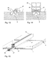
- FIG. 9 is a section of the tabletop with a ridge strip in cross section and in FIG. 15 a three-dimensional view of the tabletop with ridge bar shown.
- the ridge strip according to the invention offers a further advantage here. It serves in the in the Figures 9 and 15 illustrated embodiment additionally as a carrier element for spacers 17, which are each arranged between two boards 1. The spacers 17 ensure that, even if the individual solid wood boards 1 work, their distance from each other remains the same.
- the spacers 17 may be made of aluminum or any other weatherproof material.
- the gratings as shown in FIG. 10 is shown to be provided with a specially trained stiffening element 18.
- a stiffening element 18 For mounting, it is only necessary that after insertion of the two profile strips 2 and 3 in the ridge groove 6, the stiffening element 18 is aligned relative to the two profile strips 2 and 3 and then screwed to them with the aid of the screw 7.
- a stiffening element 18 a U-shaped chrome steel or aluminum rail can be used.
- FIG. 10 Alternative to the embodiment in FIG. 10 can be used as a stiffening element and a squared timber 19, which is bolted via a correspondingly long screw 7 with the two profile strips 2 and 3.
- the ridge strip according to the invention also allows the use of a combination of wood and metal, as they are in FIG. 12 is shown.
- a cross-sectionally clamp-shaped rail 21 is inserted into a square timber 20 and screwed by a screw 22 with the timber 20.
- the squared timber 20 can be inserted by means of the rail 21 in the grooves of the two moldings 2 and 3. This will a screwless, invisible connection between timber 20 and solid wood panel 1 allows.
- FIG. 13 an alternative embodiment of the inventive ridge strip is shown.
- This has a first profile strip 26 and a second profile strip 27, which, as in FIG. 13 is shown, are screwed into the ridge 6.
- the two profile strips 26 and 27 each have a curved surface, the radius of which is calculated so that they can be screwed by turning about its longitudinal axis with defined limited force in the groove 6.
- the tension of the two ridge strips 26 and 27 with respect to the ridge groove 6 is effected in that the sum of the two radii of the ridge strips 26 and 27 is slightly larger than the opening of the ridge 6.
- the curvatures of the two profile strips 26 and 27 can be selected such that the profile strips 26 and 27 clamped in the groove groove 6 can no longer easily turn out of the groove groove 6 themselves.
- the two profiled strips 26 and 27 are screwed into the groove 6 beyond the point of maximum tension.
- the two profile strips 26 and 27 by a in FIG. 14 shown square section 28, which is pushed into the grooves 8 of the two profile strips 26 and 27, in addition to be secured against undesired unscrewing.
- additional profile elements can be attached to the square profile 28, which was produced for example from extruded aluminum.
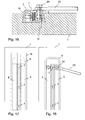
- Tensioning cables are used.
- the attachment of such a tension cable is in FIG. 16 in cross section and in FIG. 18 shown in plan view.
- the end of a tensioning cable 23 is screwed by means of a screw 24 with the profiled strip 3.
- the nut 10 which is inserted at the corresponding location in the hollow chamber of the profile strip 3.
- the ridge 6 has a dovetailed cross-section.
- the shape of the profile strips 2, 3 and 26, 27 must be adapted to the changed cross-section of the ridge to ensure a positive connection between Gratnut and Moldings.
- the two profile strips 2 and 3 or 26 and 27 are formed symmetrically. This makes it possible, with a profile strip produced by the meter, which is cut to the desired length if necessary, to form the ridge strip according to the invention.
- Another advantage of the profiled strips described is that the profiled strips can be placed together without further ado and thus are arbitrarily extendable.
- the width of the ridge groove 6 is about 2/10 mm smaller sized than would be necessary for a stress-free installation of the two profile strips.
- the 2/10 mm undersize suffice to achieve with the help of the screw 7 sufficient tension between 6 and profile strips 2 and 3.
Landscapes
- Engineering & Computer Science (AREA)
- General Engineering & Computer Science (AREA)
- Life Sciences & Earth Sciences (AREA)
- Mechanical Engineering (AREA)
- Wood Science & Technology (AREA)
- Forests & Forestry (AREA)
- Manufacturing & Machinery (AREA)
- Mutual Connection Of Rods And Tubes (AREA)
- Connection Of Plates (AREA)
- Rod-Shaped Construction Members (AREA)
- Wing Frames And Configurations (AREA)
- Floor Finish (AREA)
- Soil Working Implements (AREA)
- Chemical And Physical Treatments For Wood And The Like (AREA)
Applications Claiming Priority (1)
| Application Number | Priority Date | Filing Date | Title |
|---|---|---|---|
| EP04405347A EP1602836B1 (fr) | 2004-06-04 | 2004-06-04 | Nervure raidisseuse pour bois massif |
Related Parent Applications (2)
| Application Number | Title | Priority Date | Filing Date |
|---|---|---|---|
| EP04405347.8 Division | 2004-06-04 | ||
| EP04405347A Division EP1602836B1 (fr) | 2004-06-04 | 2004-06-04 | Nervure raidisseuse pour bois massif |
Publications (2)
| Publication Number | Publication Date |
|---|---|
| EP2042748A1 true EP2042748A1 (fr) | 2009-04-01 |
| EP2042748B1 EP2042748B1 (fr) | 2012-12-26 |
Family
ID=34932134
Family Applications (2)
| Application Number | Title | Priority Date | Filing Date |
|---|---|---|---|
| EP04405347A Expired - Lifetime EP1602836B1 (fr) | 2004-06-04 | 2004-06-04 | Nervure raidisseuse pour bois massif |
| EP09000196A Expired - Lifetime EP2042748B1 (fr) | 2004-06-04 | 2004-06-04 | Nervure raidisseuse pour bois massif |
Family Applications Before (1)
| Application Number | Title | Priority Date | Filing Date |
|---|---|---|---|
| EP04405347A Expired - Lifetime EP1602836B1 (fr) | 2004-06-04 | 2004-06-04 | Nervure raidisseuse pour bois massif |
Country Status (4)
| Country | Link |
|---|---|
| EP (2) | EP1602836B1 (fr) |
| AT (1) | ATE421642T1 (fr) |
| DE (1) | DE502004008911D1 (fr) |
| ES (1) | ES2321612T3 (fr) |
Cited By (1)
| Publication number | Priority date | Publication date | Assignee | Title |
|---|---|---|---|---|
| RU2720460C1 (ru) * | 2018-10-26 | 2020-04-30 | Юнилумин Груп Ко., Лтд. | Фиксирующее приспособление для ящиков |
Families Citing this family (5)
| Publication number | Priority date | Publication date | Assignee | Title |
|---|---|---|---|---|
| US20160017907A1 (en) * | 2014-07-16 | 2016-01-21 | Kevin Patrick Ryan | Split wedge dovetail dowel |
| DE102015005042A1 (de) * | 2015-04-21 | 2016-10-27 | Mjm Design & Technik Gmbh | Zwei- oder mehrteilige Gratleiste mit ein- oder zweiseitiger Schwalbenschwanzausbildung, zum Befestigen und/oder Verbinden von Werkstücken im Besonderen geeignet zur Herstellung und Montage von Wand-, Decken- und Bodenelementen für Holzbauten, vorzugsweise unter Verwendung von nachwachsenden Rohstoffen |
| AT524417B1 (de) * | 2021-06-08 | 2022-06-15 | Erwin Kitzmueller | Holzplatte mit wenigstens einer Gratleiste |
| CL2021003294A1 (es) * | 2021-12-10 | 2022-03-04 | Andres David Guerrero Morales | Pieza de ensamblaje con sección en forma de cola de milano. |
| CN119712688B (zh) * | 2025-01-17 | 2026-01-02 | 安徽工业大学 | 一种新型流钻螺钉及其旋转摩擦连接方法 |
Citations (4)
| Publication number | Priority date | Publication date | Assignee | Title |
|---|---|---|---|---|
| US4057294A (en) * | 1975-08-01 | 1977-11-08 | The Cincinnati Mine Machinery Company | Wedge arrangement for removably affixing a work tool or work tool holder to a base member on mining, road working or earth moving machinery, and the like |
| US5236153A (en) * | 1992-06-25 | 1993-08-17 | Laconte Richard J | Longitudinal floating pivot track fitting |
| DE4238680A1 (en) | 1992-11-17 | 1993-09-09 | Adolf Baumjohann | Seamed dovetail coupling able to be disassembled - has two=part dovetail with milled seam and trapezoidal clamping key |
| DE10201565A1 (de) | 2002-01-14 | 2003-07-24 | Draenert Studio Gmbh | Baueinheit mit wenigstens einem Grundelement |
Family Cites Families (1)
| Publication number | Priority date | Publication date | Assignee | Title |
|---|---|---|---|---|
| US5294468A (en) * | 1990-08-31 | 1994-03-15 | Taiwan Shin Yeh Enterprise Co., Ltd. | Apparatus for making furniture |
-
2004
- 2004-06-04 ES ES04405347T patent/ES2321612T3/es not_active Expired - Lifetime
- 2004-06-04 DE DE502004008911T patent/DE502004008911D1/de not_active Expired - Lifetime
- 2004-06-04 EP EP04405347A patent/EP1602836B1/fr not_active Expired - Lifetime
- 2004-06-04 EP EP09000196A patent/EP2042748B1/fr not_active Expired - Lifetime
- 2004-06-04 AT AT04405347T patent/ATE421642T1/de active
Patent Citations (4)
| Publication number | Priority date | Publication date | Assignee | Title |
|---|---|---|---|---|
| US4057294A (en) * | 1975-08-01 | 1977-11-08 | The Cincinnati Mine Machinery Company | Wedge arrangement for removably affixing a work tool or work tool holder to a base member on mining, road working or earth moving machinery, and the like |
| US5236153A (en) * | 1992-06-25 | 1993-08-17 | Laconte Richard J | Longitudinal floating pivot track fitting |
| DE4238680A1 (en) | 1992-11-17 | 1993-09-09 | Adolf Baumjohann | Seamed dovetail coupling able to be disassembled - has two=part dovetail with milled seam and trapezoidal clamping key |
| DE10201565A1 (de) | 2002-01-14 | 2003-07-24 | Draenert Studio Gmbh | Baueinheit mit wenigstens einem Grundelement |
Cited By (2)
| Publication number | Priority date | Publication date | Assignee | Title |
|---|---|---|---|---|
| RU2720460C1 (ru) * | 2018-10-26 | 2020-04-30 | Юнилумин Груп Ко., Лтд. | Фиксирующее приспособление для ящиков |
| US11480205B2 (en) | 2018-10-26 | 2022-10-25 | Unilumin Group Co., Ltd. | Box latch |
Also Published As
| Publication number | Publication date |
|---|---|
| EP2042748B1 (fr) | 2012-12-26 |
| ES2321612T3 (es) | 2009-06-09 |
| DE502004008911D1 (de) | 2009-03-12 |
| EP1602836B1 (fr) | 2009-01-21 |
| ATE421642T1 (de) | 2009-02-15 |
| EP1602836A1 (fr) | 2005-12-07 |
Similar Documents
| Publication | Publication Date | Title |
|---|---|---|
| EP2885545B1 (fr) | Système de fixation | |
| CH681383A5 (fr) | ||
| EP0136431A2 (fr) | Ossature en profilés | |
| EP2813783A1 (fr) | Support pour soutenir des panneaux solaires sur un toit plat | |
| EP3529430B1 (fr) | Montant pour une construction à montant et traverse | |
| DE69734252T2 (de) | Dachanordnung | |
| DE202015104250U1 (de) | Pfosten-Riegel-Verbindung | |
| EP1602836B1 (fr) | Nervure raidisseuse pour bois massif | |
| CH695904A5 (de) | Vorrichtung zur Aufnahme eines Lauforgans. | |
| WO2008092699A1 (fr) | Dispositif d'inspection, en particulier élément de recouvrement d'inspection | |
| EP3147419B1 (fr) | Connecteur | |
| EP2458302B1 (fr) | Elément de liaison et dispositif de fixation de modules solaires | |
| DE19623870C1 (de) | Vorrichtung zum lösbaren Verbinden von Profilstäben | |
| EP4012132B1 (fr) | Raccord en t pour montants et traverses et montants et traverses dotcomprenant un tel raccord en t | |
| EP2679759B1 (fr) | Connecteur d'angle pour châssis en corps creux | |
| DE102006001045B4 (de) | Eckverbinder für Tür- oder Fensterrahmen | |
| EP3168405B1 (fr) | Structure de châssis pour porte coulissante | |
| DE102020106891B4 (de) | T-Verbindung zwischen einem Pfosten- und Riegelprofil und Pfosten-Riegel-Konstruktion mit einer derartigen T-Verbindung | |
| DE20203512U1 (de) | Rahmensystemanordnung | |
| DE202019103487U1 (de) | Spreizbarer Eckwinkel | |
| EP2425069B1 (fr) | Dispositif d'aide à la mise à niveau pour des supports en bois/en poutre, notamment de recouvrements de balcon et de terrasse | |
| DE9407718U1 (de) | Mittel zum Befestigen und Verbinden zweier engbenachbart zueinander angeordneter Langprofile | |
| EP1491696A2 (fr) | Système d'assemblage de profilés | |
| DE202007008374U1 (de) | Plattenelement für Wände und Decken von Gebäuden | |
| DE10253417A1 (de) | Vorrichtung zum Verbinden von Wandelementen einer Trennwand |
Legal Events
| Date | Code | Title | Description |
|---|---|---|---|
| PUAI | Public reference made under article 153(3) epc to a published international application that has entered the european phase |
Free format text: ORIGINAL CODE: 0009012 |
|
| AC | Divisional application: reference to earlier application |
Ref document number: 1602836 Country of ref document: EP Kind code of ref document: P |
|
| AK | Designated contracting states |
Kind code of ref document: A1 Designated state(s): AT BE BG CH CY CZ DE DK EE ES FI FR GB GR HU IE IT LI LU MC NL PL PT RO SE SI SK TR |
|
| 17P | Request for examination filed |
Effective date: 20091001 |
|
| 17Q | First examination report despatched |
Effective date: 20091102 |
|
| AKX | Designation fees paid |
Designated state(s): CH DE LI |
|
| REG | Reference to a national code |
Ref country code: DE Ref legal event code: R079 Ref document number: 502004013967 Country of ref document: DE Free format text: PREVIOUS MAIN CLASS: F16B0002140000 Ipc: F16B0005000000 |
|
| GRAP | Despatch of communication of intention to grant a patent |
Free format text: ORIGINAL CODE: EPIDOSNIGR1 |
|
| RIC1 | Information provided on ipc code assigned before grant |
Ipc: F16B 5/00 20060101AFI20120208BHEP |
|
| RAP1 | Party data changed (applicant data changed or rights of an application transferred) |
Owner name: MEYER AG |
|
| RIN1 | Information on inventor provided before grant (corrected) |
Inventor name: MEYER AG |
|
| GRAS | Grant fee paid |
Free format text: ORIGINAL CODE: EPIDOSNIGR3 |
|
| GRAA | (expected) grant |
Free format text: ORIGINAL CODE: 0009210 |
|
| RIN1 | Information on inventor provided before grant (corrected) |
Inventor name: MEYER, RUDOLF |
|
| AC | Divisional application: reference to earlier application |
Ref document number: 1602836 Country of ref document: EP Kind code of ref document: P |
|
| AK | Designated contracting states |
Kind code of ref document: B1 Designated state(s): CH DE LI |
|
| REG | Reference to a national code |
Ref country code: CH Ref legal event code: EP |
|
| REG | Reference to a national code |
Ref country code: CH Ref legal event code: NV Representative=s name: PATENTANWALTSKANZLEI NUECKEL, CH |
|
| REG | Reference to a national code |
Ref country code: CH Ref legal event code: NV Representative=s name: PATENTANWALTSKANZLEI NUECKEL, CH |
|
| REG | Reference to a national code |
Ref country code: DE Ref legal event code: R096 Ref document number: 502004013967 Country of ref document: DE Effective date: 20130228 |
|
| PLBE | No opposition filed within time limit |
Free format text: ORIGINAL CODE: 0009261 |
|
| STAA | Information on the status of an ep patent application or granted ep patent |
Free format text: STATUS: NO OPPOSITION FILED WITHIN TIME LIMIT |
|
| 26N | No opposition filed |
Effective date: 20130927 |
|
| REG | Reference to a national code |
Ref country code: DE Ref legal event code: R097 Ref document number: 502004013967 Country of ref document: DE Effective date: 20130927 |
|
| REG | Reference to a national code |
Ref country code: CH Ref legal event code: PCAR Free format text: NEW ADDRESS: OBERDORFSTRASSE 16, 8820 WAEDENSWIL (CH) |
|
| PGFP | Annual fee paid to national office [announced via postgrant information from national office to epo] |
Ref country code: CH Payment date: 20200610 Year of fee payment: 17 |
|
| PGFP | Annual fee paid to national office [announced via postgrant information from national office to epo] |
Ref country code: DE Payment date: 20200630 Year of fee payment: 17 |
|
| REG | Reference to a national code |
Ref country code: DE Ref legal event code: R119 Ref document number: 502004013967 Country of ref document: DE |
|
| REG | Reference to a national code |
Ref country code: CH Ref legal event code: PL |
|
| PG25 | Lapsed in a contracting state [announced via postgrant information from national office to epo] |
Ref country code: LI Free format text: LAPSE BECAUSE OF NON-PAYMENT OF DUE FEES Effective date: 20210630 Ref country code: DE Free format text: LAPSE BECAUSE OF NON-PAYMENT OF DUE FEES Effective date: 20220101 Ref country code: CH Free format text: LAPSE BECAUSE OF NON-PAYMENT OF DUE FEES Effective date: 20210630 |