EP2042812A2 - Cadre porteur - Google Patents
Cadre porteur Download PDFInfo
- Publication number
- EP2042812A2 EP2042812A2 EP08105305A EP08105305A EP2042812A2 EP 2042812 A2 EP2042812 A2 EP 2042812A2 EP 08105305 A EP08105305 A EP 08105305A EP 08105305 A EP08105305 A EP 08105305A EP 2042812 A2 EP2042812 A2 EP 2042812A2
- Authority
- EP
- European Patent Office
- Prior art keywords
- support frame
- composite
- telescopic
- support
- bearing surfaces
- Prior art date
- Legal status (The legal status is an assumption and is not a legal conclusion. Google has not performed a legal analysis and makes no representation as to the accuracy of the status listed.)
- Withdrawn
Links
Images


Classifications
-
- F—MECHANICAL ENGINEERING; LIGHTING; HEATING; WEAPONS; BLASTING
- F24—HEATING; RANGES; VENTILATING
- F24C—DOMESTIC STOVES OR RANGES ; DETAILS OF DOMESTIC STOVES OR RANGES, OF GENERAL APPLICATION
- F24C15/00—Details
- F24C15/16—Shelves, racks or trays inside ovens; Supports therefor
Definitions
- the invention relates to a support frame for a household appliance, in particular an oven, and a composite of the support frame and a pull-out system.
- DE 4446757 A1 discloses a baking and roasting oven with a baking muffle and consisting of two telescopic extensions, each with a stationary and a movable part telescopic trolley.
- the support frame forms the telescopic carriage, the moving parts of the telescopic extensions or can be releasably connected to them.
- lateral receiving grid can be inserted.
- the support frame is used when using only one rack level directly to the insertion of a food support. It must not be brought into the cooking chamber in such use, the lateral receiving grid. Thus, they can not pollute.
- the food support is determined by a design of the support frame on this.
- support frames are typically made of sheet metal.
- the support frame is designed as a casting.
- the support frame is particularly stable compared to a known sheet metal construction. Also, this design affects a user high quality.
- the execution as a casting is particularly well suited to be enamelled, as compared to sheet metal versions holds enamelling evenly and without cracks or delamination on it.
- a support frame which is designed as a steel die-cast frame.
- a support frame which is enamelled is preferred.
- the support frame alternatively or additionally on at least two sets of bearing surfaces, which differ in at least one bearing surface, so z. B. differ in the number of bearing surfaces or differ in at least one bearing surface. At least two sets of bearing surfaces preferably have sets having no common bearing surfaces.
- the bearing surfaces of a set preferably comprise upper side regions of carrier frame sections, in particular for supporting a baking tray.
- the bearing surfaces of a set comprise inwardly directed projections, in particular for supporting a brewer.
- the support frame preferably comprises at least male member for mating with a pull-out system, in particular at least one slot.
- the support frame preferably additionally or alternatively comprises at least one fastening element, in particular a through-opening, for fixed but detachable fastening with a pull-out system.
- the attachment can be generally non-positive or positive.
- the object is also achieved by means of a combination of pull-out system and a support frame above.
- the pull-out system which is particularly preferably designed as a over-full extension system, preferably has two telescopic rails, which are arranged adjacent side support frame sections.
- the lateral support frame sections preferably project beyond the respectively associated telescopic rail, at least upwards.
- the extension system in particular each of the telescopic rails, at least one plug-in counter element, in particular a bolt, for engagement with an associated male member of the support frame, in particular with a respective slot o. ⁇ .
- male and Einsteckutelement on the other Be mounted base support in particular a bolt on the support frame and a slot on the telescopic rail.
- each of the telescopic rails has at least one attachment counterpart, in particular threaded bolt, for connection to the respectively associated attachment piece.
- attachment piece and attachment counterpart can be attached to the other component.
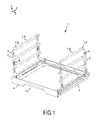
- FIG. 1 shows a Gargutlinisystem 1 for use in an oven, each with a side Einitatigitter 2, an excerpt or extract system with one attached to the respective Einitatigitter 2 telescopic rail 3 and connected to the telescopic rails 3 support frame 4.
- the telescopic rails 3 and the support frame 4 form a In normal operation stable telescopic rails / carrier frame composite as a pull-out drawer.
- On the support frame 4 different essays can be placed, for.
- a baking sheet a pizza stone, a cookware, etc.
- each suspension grille 2 has mounting plates 5 with a hole, by means of which they are fastened to a respective side wall of a baking oven muffle, z.
- each suspension grille 2 has at least one rod 7, which has a longitudinal section 8 offset from the opposite suspension grille 2 and at each of whose ends has an angled transverse section 9.
- the rods 7 protrude in the installed state thus of the lateral muffle wall by means of the transverse portion 9 leading away into the cooking chamber, with the longitudinal section 8 parallel to the insertion direction (y-direction).
- the telescopic rails 3 can then be hung by means of a suspension in the grid bars 7, as will be described in more detail below.
- the support frame 4 is connected by means of telescopic rails 3 extendable connected to the suspension grille 2.
- a user can, for example, grasp behind an engagement cutout 10 and pull the support frame 4 out of the cooking chamber counter to the drawn y-direction or retract in the y-direction.
- the pull-out system is designed as over-full extension system.
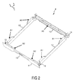
- FIG. 2 shows the support frame 4 from FIG. 1 alone.
- the support frame 4 has a circumferential frame-shaped basic shape, wherein a front support frame portion 11, the side support frame portions 12 and a rear support frame portion 13 are integrally formed as an enameled casting.
- a sand mold method using a lost sand mold is preferably used.
- a centrifugal casting method can be used.
- the rear support frame portion 13 has at its ends in each case to the rear (in the y direction) angled portions which also have a rearwardly directed recess or slot 14.
- the lateral support frame sections 12 indicate their front end region laterally (in the y / z plane) outgoing areas, each having a vertical passage opening 15.
- the structure as a steel die-cast frame allows a very good enameling, especially resistant enamelling.
- Such a framework is pyrolyzable.
- the illustrated support frame 4 is further configured to have two sets of support surfaces A1, A2 for different attachments.
- the bearing surfaces A1 for a baking sheet correspond to upper side regions of the lateral support frame sections 12.
- the support surfaces A2 for a roaster correspond with respect to the support frame 4 inwardly directed projections of the front support frame section 11 and the rear support frame section thirteenth
- the support frame 4 is connected in normal operation with the extension system, the drawer / support frame composite (telescopic drawer) is preferably easy to insert into each plane of the side Einitatigitter and latched securely, as will be described in more detail below.
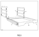
- FIG. 3 shows the Gargutlinisystem 1 from FIG. 1 , in which now the extraction system / support frame composite of telescopic rails 3 and support frame 4 is separated from the suspension grille 2. At their rear end region, the respective telescopic rail 3 in each case has a supporting angle 16.
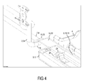
- FIG. 4 shows the Gargutierisystem 1 from FIG. 3 enlarged in the region of a support bracket 16.
- the telescopic rail 3 has an elongated suspension element 18 for suspension on the rod 7 of the hook-in grid 2.
- the suspension element 18 is considered to be configured by the telescopic rail 3 upwardly extending sheet metal, which is bent in a U-shape in the direction of the rod 7 out.
- the suspension element 18 is arranged so that it can rest or be suspended on the rod 7 while permitting a relative displacement or slippage, and thus hold the composite of the telescopic rail 3 and the support frame 4 on the suspension grid 2.
- the plateau region 20 lies at least at its rear end at least by a vertical distance (in the x direction) lower than the vertex of the U-shaped suspension element 18 or suspension element region, which is at least the height (in the x direction) of the transverse section 9 of the rod 7 equivalent.
- the plateau region 20 is removed by the value of the height of the transverse portion 9 from the (inner) apex of the U-shaped suspension member 18, or more.
- a stop in the form of a spring 21 is attached, which is at least partially less than the height of the transverse portion 9 from the (inner) vertex of the suspension member 18 is removed.
- the suspension element 18 does not reach all the way to the rear end of the telescopic rod 3, where the sheet is designed rather than the support bracket 16.
- the support bracket 16 is formed as a right angle to the outside angled sheet, the altitude (corresponding to the x-coordinate) of the lateral buckling fold corresponds to the apex of the suspension element 18.
- the support bracket 16 is bent at a projecting rearward over the telescopic rail 3 area down.
- the support bracket 16 has an upper support area 22 which is located at the level of the apex of the suspension element 18 and a sliding area 23 which is offset downwards.
- the sliding area 23 is at least as deep as the plateau area 20.
- the suspension element 18 is so narrow that it does not or only just touches a vertical strut 24 of the hanging grid.
- the sliding portion 23 When inserting the extension system 3 in a cooking chamber, the sliding portion 23 is first placed on the rod. Since the suspension member 18 is sufficiently narrow, it slides past the vertical strut 24 upon insertion. Especially if the sliding region 23 is lower than the plateau region 20, the extension system 3 slides in the rear only on the back, which allows a relatively easy insertion.
- the U-shaped suspension member 18 is arranged so that, when the sliding portion 23 slides on the longitudinal portion 8, it is located with the corresponding length above the longitudinal portion 8 of the rod 7.
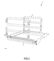
- FIG. 5 shows the Gargutlinisystem 1 in a state in which the telescopic rail 3 and the associated support frame 4 are inserted so far into the suspension grid 2, that the sliding portion rests on the rear cross section. In this position, there is already a predominant part of the suspension element 18 above the rod. 7
- FIG. 6 shows the Gargutlinisystem 1 fragmentary in a state in which the extension system 3 is already inserted so far that the sliding portion 23 and the angled portion between the sliding portion 23 and the support portion 22 slid behind the rear cross section 9.
- the longitudinal section 8 of the rod 7 now rests on the support region 22 and on the suspension element 18 as shown.
- the drawer system 3 is not yet fully inserted, so that the plateau region 20 is still in front of the rear transverse section 9.
- FIG. 8 shows the Gargut lymph system 1 in the fully inserted state in the front area.
- the suspension element 18 has a forwardly projecting latching area 25 in the form of an upwardly angled sheet.
- the front area can fall down by its weight or be pressed by the user, that the latching portion 25 engages the front cross section 9 of the rod and holds there.
- the front area of the extension system / carrier frame composite is secured against accidental lifting or jumping out.
- the latching by the user can be easily solved by appropriate application of force again and so the pull-out system / carrier frame composite remove by pulling out the suspension grille 2, z. B. for a pyrolysis or for insertion into another oven level.
- FIG. 8 further shows a screw in which the front attachment of the support frame 4, a vertically upstanding, welded to the telescopic rail 3 threaded bolt 26 is guided through the through hole 15 of the support frame 4 and tightened by a matching knurled nut 27.
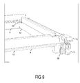
- FIG. 9 shows the pullout system / carrier frame composite from behind with a view of the rearwardly directed slot 14 of the support frame 4, in which for attachment to the pullout system 3 directed in the direction of the support frame 4, welded pin 28 of the telescopic rail 3 is inserted.
- FIG. 9 also shows a Radienaussteififung 29 between a side support frame portion 12 and the front support frame portion 11 for further improving the rigidity of the support frame 4th
- the lateral support frame sections 12 projects beyond the respective associated telescopic rail 3 upwards, so that this against contamination, for. B. fat splash, is better protected.
- the pull-out system can also be self-supporting; z. B. as two telescopic rails, which are connected by means of a scaffold.
Landscapes
- Engineering & Computer Science (AREA)
- Chemical & Material Sciences (AREA)
- Combustion & Propulsion (AREA)
- Mechanical Engineering (AREA)
- General Engineering & Computer Science (AREA)
- Baking, Grill, Roasting (AREA)
Applications Claiming Priority (1)
| Application Number | Priority Date | Filing Date | Title |
|---|---|---|---|
| DE200710045746 DE102007045746A1 (de) | 2007-09-25 | 2007-09-25 | Trägerrahmen |
Publications (2)
| Publication Number | Publication Date |
|---|---|
| EP2042812A2 true EP2042812A2 (fr) | 2009-04-01 |
| EP2042812A3 EP2042812A3 (fr) | 2012-01-11 |
Family
ID=40219934
Family Applications (1)
| Application Number | Title | Priority Date | Filing Date |
|---|---|---|---|
| EP08105305A Withdrawn EP2042812A3 (fr) | 2007-09-25 | 2008-09-11 | Cadre porteur |
Country Status (2)
| Country | Link |
|---|---|
| EP (1) | EP2042812A3 (fr) |
| DE (1) | DE102007045746A1 (fr) |
Cited By (1)
| Publication number | Priority date | Publication date | Assignee | Title |
|---|---|---|---|---|
| DE102010017115A1 (de) * | 2010-05-27 | 2011-12-01 | Paul Hettich Gmbh & Co. Kg | Auszugführung |
Families Citing this family (1)
| Publication number | Priority date | Publication date | Assignee | Title |
|---|---|---|---|---|
| DE202008010190U1 (de) * | 2008-07-30 | 2009-12-10 | Paul Hettich Gmbh & Co. Kg | Auszugsvorrichtung für ein Haushaltsgerät |
Citations (2)
| Publication number | Priority date | Publication date | Assignee | Title |
|---|---|---|---|---|
| DE4446757A1 (de) | 1994-12-24 | 1996-06-27 | Miele & Cie | Back- und Bratofen mit einem Teleskopwagen |
| DE19505470A1 (de) * | 1995-02-17 | 1996-08-22 | Schott Glaswerke | Topfträger für Gaskochmulden |
Family Cites Families (3)
| Publication number | Priority date | Publication date | Assignee | Title |
|---|---|---|---|---|
| US4640265A (en) * | 1986-02-24 | 1987-02-03 | Romo H Duane | Insert for converting a conventional home oven into a pizza oven |
| DE19951689C1 (de) * | 1999-10-27 | 2001-04-12 | Aeg Hausgeraete Gmbh | Einschubvorrichtung für Gargutträger im Garraum von Garöfen |
| EP1376019A1 (fr) * | 2002-06-17 | 2004-01-02 | Electrolux Home Products Corporation N.V. | Moufle pour four de cuisson |
-
2007
- 2007-09-25 DE DE200710045746 patent/DE102007045746A1/de not_active Withdrawn
-
2008
- 2008-09-11 EP EP08105305A patent/EP2042812A3/fr not_active Withdrawn
Patent Citations (2)
| Publication number | Priority date | Publication date | Assignee | Title |
|---|---|---|---|---|
| DE4446757A1 (de) | 1994-12-24 | 1996-06-27 | Miele & Cie | Back- und Bratofen mit einem Teleskopwagen |
| DE19505470A1 (de) * | 1995-02-17 | 1996-08-22 | Schott Glaswerke | Topfträger für Gaskochmulden |
Cited By (2)
| Publication number | Priority date | Publication date | Assignee | Title |
|---|---|---|---|---|
| DE102010017115A1 (de) * | 2010-05-27 | 2011-12-01 | Paul Hettich Gmbh & Co. Kg | Auszugführung |
| US9038623B2 (en) | 2010-05-27 | 2015-05-26 | Paul Hettich Gmbh & Co. Kg | Pull-out guide |
Also Published As
| Publication number | Publication date |
|---|---|
| EP2042812A3 (fr) | 2012-01-11 |
| DE102007045746A1 (de) | 2009-04-02 |
Similar Documents
| Publication | Publication Date | Title |
|---|---|---|
| DE10151899C1 (de) | Schienensystem für Gargutträger in einem Backofen | |
| DE3628763C2 (fr) | ||
| DE102006015444B4 (de) | Teleskopauszugsvorrichtung zur Befestigung an einem in dem Behandlungsraum eines Haushaltsgeräts angeordneten Traggestell | |
| DE10051153B4 (de) | Gargutträgersystem für einen Backofen | |
| EP1225806A1 (fr) | Systeme de support d'article a cuire destine a un four | |
| EP4293287B1 (fr) | Rail télescopique | |
| DE102007045745A1 (de) | Ausziehschublade | |
| DE102011080183A1 (de) | Auflagerost für ein Gargerät | |
| DE19515080C2 (de) | Grillgerät insbesondere mit Holzkohlefeuerung | |
| DE102009046573A1 (de) | Teleskopauszugsvorrichtung für ein Hausgerät, Hausgrät mit einer derartigen Teleskopauszugsvorrichtung sowie Verfahren zum Befestigen einer Teleskopauszugsvorrichtung an einem Traggestell zur Aufnahme zumindest eines Gargutträgers | |
| EP1788313A2 (fr) | Dispositif d'extraction pour appareil ménager | |
| DE4014823C2 (de) | Herd mit einer Backmuffel und mit einem auf Teleskopauszügen verschiebbaren Tragrahmen | |
| EP1761731B1 (fr) | Systeme de guidage lineaire destine a un tiroir | |
| EP2042812A2 (fr) | Cadre porteur | |
| DE19951689C1 (de) | Einschubvorrichtung für Gargutträger im Garraum von Garöfen | |
| EP2226566A2 (fr) | Four à pâtisseries doté d'un système de nettoyage pyrolytique ainsi qu'élément de retenue de plateau de cuisson pour ce four | |
| EP1553352B1 (fr) | Appareil ménager, en particulier appareil de cuisson et procédé pour sa fabrication | |
| EP1553350B1 (fr) | Appareil de cuisson | |
| DE4446757C3 (de) | Back- und Bratofen mit einem Teleskopwagen | |
| DE102008041496A1 (de) | Lagerstelle für ein Flächenelement einer Dunstabzugshaube | |
| EP2284447B1 (fr) | Moufle pour four de cuisson | |
| DE102022113764A1 (de) | Schnellbefestigungssystem für einen Teleskopauszug | |
| DE102005014738B4 (de) | Gargutaufnahmevorrichtung für Heissluftdämpfer | |
| EP0716269B1 (fr) | Revêtement amovible pour intérieur de fours | |
| DE10241489A1 (de) | Teleskopartiges System und Auszug für einen Gargutträger |
Legal Events
| Date | Code | Title | Description |
|---|---|---|---|
| PUAI | Public reference made under article 153(3) epc to a published international application that has entered the european phase |
Free format text: ORIGINAL CODE: 0009012 |
|
| AK | Designated contracting states |
Kind code of ref document: A2 Designated state(s): AT BE BG CH CY CZ DE DK EE ES FI FR GB GR HR HU IE IS IT LI LT LU LV MC MT NL NO PL PT RO SE SI SK TR |
|
| AX | Request for extension of the european patent |
Extension state: AL BA MK RS |
|
| PUAL | Search report despatched |
Free format text: ORIGINAL CODE: 0009013 |
|
| AK | Designated contracting states |
Kind code of ref document: A3 Designated state(s): AT BE BG CH CY CZ DE DK EE ES FI FR GB GR HR HU IE IS IT LI LT LU LV MC MT NL NO PL PT RO SE SI SK TR |
|
| AX | Request for extension of the european patent |
Extension state: AL BA MK RS |
|
| RIC1 | Information provided on ipc code assigned before grant |
Ipc: F24C 15/16 20060101AFI20111208BHEP |
|
| 17P | Request for examination filed |
Effective date: 20120711 |
|
| AKX | Designation fees paid |
Designated state(s): AT BE BG CH CY CZ DE DK EE ES FI FR GB GR HR HU IE IS IT LI LT LU LV MC MT NL NO PL PT RO SE SI SK TR |
|
| RAP1 | Party data changed (applicant data changed or rights of an application transferred) |
Owner name: BSH HAUSGERAETE GMBH |
|
| 17Q | First examination report despatched |
Effective date: 20160510 |
|
| STAA | Information on the status of an ep patent application or granted ep patent |
Free format text: STATUS: EXAMINATION IS IN PROGRESS |
|
| GRAP | Despatch of communication of intention to grant a patent |
Free format text: ORIGINAL CODE: EPIDOSNIGR1 |
|
| STAA | Information on the status of an ep patent application or granted ep patent |
Free format text: STATUS: GRANT OF PATENT IS INTENDED |
|
| INTG | Intention to grant announced |
Effective date: 20201028 |
|
| STAA | Information on the status of an ep patent application or granted ep patent |
Free format text: STATUS: THE APPLICATION IS DEEMED TO BE WITHDRAWN |
|
| 18D | Application deemed to be withdrawn |
Effective date: 20210310 |