EP2042818A2 - Klimaanlagensystem mit mehreren Datenverbindungsleitungen zwischen Innen- und Ausseneinheit und Schalteinrichtung für diese Verbindungen - Google Patents
Klimaanlagensystem mit mehreren Datenverbindungsleitungen zwischen Innen- und Ausseneinheit und Schalteinrichtung für diese Verbindungen Download PDFInfo
- Publication number
- EP2042818A2 EP2042818A2 EP20080016779 EP08016779A EP2042818A2 EP 2042818 A2 EP2042818 A2 EP 2042818A2 EP 20080016779 EP20080016779 EP 20080016779 EP 08016779 A EP08016779 A EP 08016779A EP 2042818 A2 EP2042818 A2 EP 2042818A2
- Authority
- EP
- European Patent Office
- Prior art keywords
- communication
- communication circuit
- power supply
- outdoor unit
- circuit
- Prior art date
- Legal status (The legal status is an assumption and is not a legal conclusion. Google has not performed a legal analysis and makes no representation as to the accuracy of the status listed.)
- Granted
Links
- 238000004891 communication Methods 0.000 title claims abstract description 219
- 238000004378 air conditioning Methods 0.000 claims abstract description 21
- 230000005540 biological transmission Effects 0.000 description 32
- 238000010276 construction Methods 0.000 description 31
- 238000010586 diagram Methods 0.000 description 16
- 230000018199 S phase Effects 0.000 description 14
- 238000009434 installation Methods 0.000 description 11
- 229910001219 R-phase Inorganic materials 0.000 description 8
- 230000006870 function Effects 0.000 description 6
- 238000000034 method Methods 0.000 description 6
- 238000007664 blowing Methods 0.000 description 3
- 238000001514 detection method Methods 0.000 description 3
- 230000002238 attenuated effect Effects 0.000 description 2
- 238000012986 modification Methods 0.000 description 2
- 230000004048 modification Effects 0.000 description 2
- 239000003990 capacitor Substances 0.000 description 1
- 239000000470 constituent Substances 0.000 description 1
- 239000003507 refrigerant Substances 0.000 description 1
- 230000004044 response Effects 0.000 description 1
- 239000004065 semiconductor Substances 0.000 description 1
- 238000007493 shaping process Methods 0.000 description 1
Images


Classifications
-
- F—MECHANICAL ENGINEERING; LIGHTING; HEATING; WEAPONS; BLASTING
- F24—HEATING; RANGES; VENTILATING
- F24F—AIR-CONDITIONING; AIR-HUMIDIFICATION; VENTILATION; USE OF AIR CURRENTS FOR SCREENING
- F24F11/00—Control or safety arrangements
- F24F11/30—Control or safety arrangements for purposes related to the operation of the system, e.g. for safety or monitoring
-
- F—MECHANICAL ENGINEERING; LIGHTING; HEATING; WEAPONS; BLASTING
- F24—HEATING; RANGES; VENTILATING
- F24F—AIR-CONDITIONING; AIR-HUMIDIFICATION; VENTILATION; USE OF AIR CURRENTS FOR SCREENING
- F24F1/00—Room units for air-conditioning, e.g. separate or self-contained units or units receiving primary air from a central station
- F24F1/0003—Room units for air-conditioning, e.g. separate or self-contained units or units receiving primary air from a central station characterised by a split arrangement, wherein parts of the air-conditioning system, e.g. evaporator and condenser, are in separately located units
-
- F—MECHANICAL ENGINEERING; LIGHTING; HEATING; WEAPONS; BLASTING
- F24—HEATING; RANGES; VENTILATING
- F24F—AIR-CONDITIONING; AIR-HUMIDIFICATION; VENTILATION; USE OF AIR CURRENTS FOR SCREENING
- F24F1/00—Room units for air-conditioning, e.g. separate or self-contained units or units receiving primary air from a central station
- F24F1/06—Separate outdoor units, e.g. outdoor unit to be linked to a separate room comprising a compressor and a heat exchanger
- F24F1/20—Electric components for separate outdoor units
-
- F—MECHANICAL ENGINEERING; LIGHTING; HEATING; WEAPONS; BLASTING
- F24—HEATING; RANGES; VENTILATING
- F24F—AIR-CONDITIONING; AIR-HUMIDIFICATION; VENTILATION; USE OF AIR CURRENTS FOR SCREENING
- F24F11/00—Control or safety arrangements
- F24F11/30—Control or safety arrangements for purposes related to the operation of the system, e.g. for safety or monitoring
- F24F11/46—Improving electric energy efficiency or saving
-
- F—MECHANICAL ENGINEERING; LIGHTING; HEATING; WEAPONS; BLASTING
- F24—HEATING; RANGES; VENTILATING
- F24F—AIR-CONDITIONING; AIR-HUMIDIFICATION; VENTILATION; USE OF AIR CURRENTS FOR SCREENING
- F24F11/00—Control or safety arrangements
- F24F11/62—Control or safety arrangements characterised by the type of control or by internal processing, e.g. using fuzzy logic, adaptive control or estimation of values
-
- F—MECHANICAL ENGINEERING; LIGHTING; HEATING; WEAPONS; BLASTING
- F24—HEATING; RANGES; VENTILATING
- F24F—AIR-CONDITIONING; AIR-HUMIDIFICATION; VENTILATION; USE OF AIR CURRENTS FOR SCREENING
- F24F11/00—Control or safety arrangements
- F24F11/89—Arrangement or mounting of control or safety devices
-
- F—MECHANICAL ENGINEERING; LIGHTING; HEATING; WEAPONS; BLASTING
- F24—HEATING; RANGES; VENTILATING
- F24F—AIR-CONDITIONING; AIR-HUMIDIFICATION; VENTILATION; USE OF AIR CURRENTS FOR SCREENING
- F24F11/00—Control or safety arrangements
- F24F11/30—Control or safety arrangements for purposes related to the operation of the system, e.g. for safety or monitoring
- F24F11/32—Responding to malfunctions or emergencies
-
- F—MECHANICAL ENGINEERING; LIGHTING; HEATING; WEAPONS; BLASTING
- F25—REFRIGERATION OR COOLING; COMBINED HEATING AND REFRIGERATION SYSTEMS; HEAT PUMP SYSTEMS; MANUFACTURE OR STORAGE OF ICE; LIQUEFACTION SOLIDIFICATION OF GASES
- F25B—REFRIGERATION MACHINES, PLANTS OR SYSTEMS; COMBINED HEATING AND REFRIGERATION SYSTEMS; HEAT PUMP SYSTEMS
- F25B2313/00—Compression machines, plants or systems with reversible cycle not otherwise provided for
- F25B2313/023—Compression machines, plants or systems with reversible cycle not otherwise provided for using multiple indoor units
Definitions
- the present invention relates to an outdoor unit and an air conditioning system using the same.
- the present invention has been implemented in view of the foregoing situation, and has an object to provide an outdoor unit and an air conditioning system in which equipment can be easily added or replaced.
- an air conditioning system in which an indoor unit and an outdoor unit are connected to each other through common power supply lines is characterized in that the indoor unit has at least one of a first communication circuit for performing communications through two communication lines independent of the power supply lines and a second communication circuit for performing communications through one of the power supply lines and one communication line independent of the power supply lines, and the outdoor unit has a third communication circuit that is connected to the indoor unit having at least one of the first communication circuit and the second communication circuit and communicates with one of the first communication circuit and the second communication circuit, and a switch for connecting one of communication terminals of the third communication circuit to one of the power supply lines when the third communication circuit is connected to the second communication circuit, and releasing the connection concerned when the third communication circuit is connected to the first communication circuit.
- the switching operation of the switch of the outdoor unit is controlled in accordance with whether the indoor unit has the first communication circuit or the second communication circuit, whereby the third communication circuit is connected to the first or second communication circuit. Accordingly, the switch carries out the switching operation thereof in accordance with whether the indoor unit has the first communication circuit or the second communication circuit, whereby equipment (an outdoor unit and an indoor unit) can be easily additionally provided or replaced.
- the indoor unit has both the first communication circuit and the second communication circuit, and the switch of the outdoor unit carries out a switching operation in accordance with whether the outdoor unit is connected to the first communication circuit or the second communication circuit.
- the indoor unit can be connected to the outdoor unit by selecting any one of the first communication circuit and the second communication circuit provided to the indoor unit. Therefore, the indoor unit can be additionally provided or replaced irrespective of the communication system which the existing facilities adopt.
- one of the communication terminals of the third communication circuit is a terminal connected to the ground of the third communication circuit, and the switch connects the terminal connected to the ground of the third communication circuit to one of the power supply lines.
- the switch when the switch is set to ON-state, the ground of the third communication circuit and one of the power supply lines are connected to each other. Accordingly, the communication can be stably performed when an indoor unit executing communications by using a power supply line is connected.
- the outdoor unit has a noise filter between a load thereof and the power supply lines
- the switch connects the one of the power supply lines at the input side of the noise filter to the terminal connected to the ground of the third communication circuit
- the indoor unit has a noise filter between a load thereof and the power supply lines
- the second communication circuit is connected to one of the power supply lines at the input side of the noise filter.
- the switch is connected to the input side of the noise filter in the outdoor unit, and the second communication circuit is connected to one of the power supply lines at the input side of the noise filter in the indoor unit. Accordingly, a communication signal can be prevented from being attenuated by the noise filter.
- an outdoor unit that is connectable through common power supply lines to an indoor unit having at least one of a first communication circuit for performing communications through two communication lines independent of the power supply lines and a second communication circuit for performing communications through one of the power supply lines and one communication line independent of the power supply lines, is characterized in that the outdoor unit has a third communication circuit for communicating with one of the first communication circuit and the second communication circuit when the outdoor unit is connected to the indoor unit, and a switch for connecting one of communication terminals of the third communication circuit to one of the power supply lines when the third communication circuit is connected to the second communication circuit, and releasing the connection concerned when the third communication circuit is connected to the first communication circuit.
- the switching operation of the outdoor unit is controlled in accordance with whether the indoor unit has the first communication circuit or the second communication circuit, whereby the third communication circuit is connected to the first communication circuit or the second communication circuit. Accordingly, by controlling the switching operation of the switch in accordance with the condition of existing facilities, equipment (an outdoor unit and an indoor unit) can be easily additionally provided or replaced.
- an air conditioning system and an outdoor unit with which equipment can be easily additionally provided or replaced there can be easily provided an air conditioning system and an outdoor unit with which equipment can be easily additionally provided or replaced.
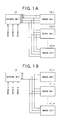
- Fig. 1A and 1B are diagrams showing the construction of a first embodiment of the present invention.
- Fig. 1A shows the construction when indoor units 20-1 to 20-n are connected to an outdoor unit 10 to perform communications by using two communication lines (SG2,SG2) which are independent of power supply lines
- Fig. 1B shows an example of the construction when indoor units 21-1 to 21-n are connected to an outdoor unit 10 to perform communications by using one (S1) of power supply lines and one communication line (SG) independent of power supply lines.
- S1 power supply lines
- SG communication line independent of power supply lines
- the outdoor unit 10 and the indoor units 20-1 to 20-n are connected to one another through totally four connection lines, and thus this will be referred to as "4-wire type”.
- the outdoor unit 10 and the indoor units 21-1 to 21-n are connected to one another through totally three connection lines, and thus this will be referred to as 3-wire type".
- the outdoor unit 10 and the indoor units 20-1 to 20-n are mutually connected to one another through two communication lines SG1, SG2 and two power supply lines S1, R1.
- the outdoor unit 10 and the indoor units 20-1 to 20-n are connected to the communication lines SG1, SG2 in a bus style, and perform communications in a serial communication style.
- the power supply lines S1, R1 supplies the indoor units 20-1 to 20-n with S-phase and R-phase power out of three-phase AC power of R-phase, S-phase and T-phase supplied to the outdoor unit 10.
- the outdoor unit 10 and the indoor units 21-1 to 21-n are mutually connected to one another through one communication line SG and two power supply lines S1, R1.
- a serial signal is transmitted to the communication line SG and the power supply line S1.
- the outdoor unit 10 and the indoor units 21-1 to 21-n are connected to the communication line SG and the power supply line S1 in a bus style.
- the power supply lines S1, R1 supply the indoor units 21-1 to 21-n with S-phase and R-phase power out of three-phase AC power of R-phase, S-phase and T-phase supplied to the outdoor unit 10.
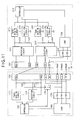
- Fig. 2 is a block diagram showing an example of the electrical construction of the outdoor unit 10 and the indoor unit 20-1 shown in Fig. 1A .
- the indoor units 20-1 to 20-n have the same construction, and thus the following description will be made by representatively using the indoor unit 20-1.
- the outdoor unit 10 mainly comprises a controller 100, a transmission circuit 110 ("third communication circuit” in claims), a reception circuit 120 ("third communication circuit” in claims), resistors 130, 140, a terminal table 150, a switch 160 ("switch” in claims), a noise filter 170 and a load 180.
- the controller 100 comprises CPU (Central Processing Unit) , ROM (Read Only Memory), RAM (Random Access Memory) , etc., and it communicates with the indoor units 20-1 to 20-n through the transmission circuit 110 and the reception circuit 120 and also controls the load 180, etc. on the basis of the communication result or the like.
- the transmission circuit 110 generates a serial signal on the basis of data supplied from the controller 100, and transmits the serial signal to the indoor units 20-1 to 20-n through the terminal table 150.
- the reception circuit 120 receives the serial signal transmitted from the indoor units 20-1 to 20-n, restores the serial signal to the original data and supplies the original data to the controller 100.
- the resistors 130, 140 function as input/output resistors for the transmission circuit 110 and the reception circuit 120.
- the communication lines SG1, SG2, the power supply lines S1, R1 and the three-phase AC power supply lines (the lines corresponding to T-phase, S-phase and R-phase in Fig. 2 ) are connected to the terminal table 150.
- the switch 160 is constructed by an electromagnetic relay or the like, for example, and when it is set to ON-state, it connects the ground of the transmission circuit 110 and the reception circuit 120 to the S-phase of the power supply.
- the noise filter 170 is a filter for removing or attenuating noise superposed on the three-phase AC power, and it is constructed by a low pass filter, for example.
- the load 180 is constructed by a compressor for compressing refrigerant, an air blowing fan, a stepping motor for controlling an outdoor expansion valve, etc., for example.
- the indoor unit 20-1 mainly comprises a terminal table 200, a rectifying circuit 210, resistors 230, 240, a transmission circuit 270 (corresponding to "first communication circuit” in claims), a reception circuit 290 (corresponding to "first communication circuit” in claims), a controller 310, a noise filter 320 and a load 330.
- communication lines SG1, SG2 and power supply lines S1, R1 are connected to the terminal table 200.
- the rectifying circuit 210 rectifies serial signals (signals having a low or high state) transmitted through the communication lines SG1, SG2. Accordingly, the serial signal is nonpolarized, and communication is enabled irrespective of which terminal of the terminal table the communication lines SG1, SG2 are connected to.
- the resistors 230, 240 function as input/output resistors for the transmission circuit 270 and the reception circuit 290.
- the transmission circuit 270 converts data supplied from the controller 310 to a serial signal, and transmits the serial signal through the rectifying circuit 210 and the terminal table 200.
- the reception circuit 290 receives the serial signal transmitted from the outdoor unit 10, restores the serial signal to the corresponding data and then supplies the data concerned to the controller 310.
- the controller 310 is constructed by CPU, ROM, RAM, etc., for example, and it communicates with the outdoor unit through the transmission circuit 270 and the reception circuit 290 and also controls the load 330 and the other units on the basis of the communication result, etc.
- Fig. 3 is a circuit diagramshowing an example of the detailed construction of the outdoor unit 10 shown in Fig. 2 .
- the outdoor unit 10 mainly comprises a controller 100, transistors 111, 113, 118, 122, resistors 112, 114, 116, 117, 121, 123, 125, 130, 140, photocouplers 115, 124 and a load 180.
- the emitter of the transistor 118 is supplied with DC power generated by a power supply circuit having a transformer 191, a bridge diode 192, a capacitor 193 and a resistor 194.
- the transistors 111, 113, 118, the resistors 112, 114, 116, 117 and the photocoupler 115 constitute the transmission circuit 110.
- the transistor 122, the resistors 121, 123, 125, the zener diode 126 and the photocoupler 124 constitute the reception circuit 120.
- the transistors 111, 113 and the resistor 112 constitute a non-inverting amplifying circuit, and it amplifies data output from the controller 100 and supplies the amplified data to the photocoupler 115.
- the photocoupler 115 emits light from a built-in LED (Light Emitting Diode) in accordance with current flowing in the collector of the transistor 113, receives the light by a built-in photodiode to convert the intensity of the light to an electrical signal and then outputs the electrical signal.
- the transistor 118 and the resistors 116, 117 switch the power supply voltage (for example, 24V) supplied from the resistor in accordance with the output of the photocoupler 115, and outputs the voltage to both the ends of the resistors 130, 140.
- the zener diode 126 ha a function of waveform-shaping the voltage applied across the resistor 140.
- the resistor 125 limits current flowing to the input side of the photocoupler 124.
- the photocoupler 124 emits light from a built-in LED in accordance with the voltage output from the resistor 125, converts the light to an electrical signal by a built-in photodiode and then outputs the electrical signal.
- the resistor 123 limits the current flowing in the photocoupler 124 and the transistor 122.
- the transistor 122 and the resistor 121 constitutes an inverting amplifying circuit, and it inverts and amplifies the output voltage of the photocoupler 124 and supplies the inverted and amplified output voltage to the controller 100.
- the switch 160 When the switch 160 is set to ON-state in accordance with the control of the controller 100, the switch 160 connects the ground side of the transmission circuit 110 and the reception circuit 120 (the collector side of the transistor 118) to the S-phase of the three-phase AC (the input side of the noise filter 170).
- the switch 160 connects the ground side of the transmission circuit 110 and the reception circuit 120 (the collector side of the transistor 118) to the S-phase of the three-phase AC (the input side of the noise filter 170).
- Each of the T-phase, S-phase and R-phase of the three-phase AC power supplied to the terminal table 150 is supplied to the load 180 through the noise filter 170, and also the S-phase and the R-phase are supplied to the indoor units 20-1 to 20-n through the terminal table 150.
- Fig. 4 is a circuit diagram showing an example of the detailed construction of the indoor unit 20-1 shown in Fig. 2 .
- the indoor unit 20-1 mainly comprises a terminal 200, noise filters 211, 320, a bridge diode 212, resistors 230, 240, 272, 273, 275, 277, 292, 294, 296, transistors 271, 276, 278, 295, photocouplers 274, 293, a zener diode 291, a controller 310 and a load 330.
- the noise filter 211 and the bridge diode 212 constitute a rectifying circuit 210.
- the transistors 271, 276, 278, the resistors 272, 273, 275, 277 and the photocoupler 274 constitute the transmission circuit 270.
- the transistor 295, the resistors 2292, 294, 296, the zener diode 291 and the photocoupler 293 constitute the reception circuit 290.
- the transistors 278, 276 and the resistor 277 constitute a non-inverting amplifying circuit, and it inverts and amplifies the signal output from the controller 310 and supplies the inverted and amplified signal to the photocoupler 274.
- the photocoupler 274 emits light from a built-in LED in accordance with current flowing in the collector of the transistor 276, converts the emitted light to an electrical signal by a built-in photodiode and outputs the electrical signal.
- the transistor 271 amplifies the output of the photocoupler 274 and outputs the amplified output to the resistors 230, 240.
- the zener diode 291 shapes the waveform of the voltage appearing at the resistor 240 and outputs the waveform-shaped voltage.
- the resistor 292 limits the current flowing to the input terminal of the photocoupler 293.
- the photocoupler 293 emits light from a built-in LED in accordance with current flowing through the resistor 292, and outputs the voltage corresponding to the intensity of the emitted light by a built-in photodiode.
- the transistor 295 and the resistor 296 constitute an inverting amplifying circuit, and it inverts the output of the photocoupler 293 and outputs it to the controller 310.
- the noise filter 320 is inserted between the terminal table 200 and the load 330, and removes or attenuates high frequency components contained in power supplied from the outdoor unit 10 through the power supply line.
- the load 330 is constructed by the air blowing fan, the stepping motor for controlling the indoor expansion valve, etc.
- Fig. 5 is a block diagram showing an example of the electrical construction of the outdoor 10 and the indoor unit 21-1 shown in Fig. 1B .
- the indoor units 21-1 to 21-n have the same construction, and thus the description will be made hereunder by using the indoor unit 21-1 representatively.
- the outdoor unit 10 has the same construction as shown in Fig. 2 , and thus the description thereof is omitted.
- the indoor unit 21-1 mainly comprises a terminal table 201, a rectifying circuit 220, resistors 250, 260, a transmission circuit 280 (corresponding to "second communication circuit” in claims), a reception circuit 300 (corresponding to "second communication circuit” in claims), a controller 310, a noise filter 320 and a load 330.
- the corresponding parts to those of Fig. 2 are represented by the same reference numerals.
- a communication line SG1 and power supply lines S1, R1 are connected to the terminal table 201.
- the rectifying circuit 220 rectifies serial signals transmitted through the communication line SG and the power supply line S1, thereby nonpolarizing the serial signals.
- the resistors 250, 260 function as input/output resistors for the transmission circuit 280 and the reception circuit 300.
- the transmission circuit 280 converts data supplied from the controller 310 to a serial signal, and transmits the serial signal through the rectifying circuit 220 and the terminal table 201.
- the reception circuit 300 receives the serial signal from the outdoor unit 10, restores the serial signal to the corresponding data and then supplies the restored data to the controller 310.
- the controller 310 is constructed by CPU, ROM, RAM, etc., and it communicates with the outdoor unit 10 through the transmission circuit 280 and the reception circuit 300, and also controls the load 330, etc. on the basis of the communication result or the like.
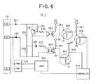
- Fig. 6 is a circuit diagramshowing an example of the detailed construction of the indoor unit 21-1 shown in Fig. 5 .
- the indoor unit 21-1 mainly comprises a terminal table 201, diodes 221, 222, resistors 250, 260, 282, 283, 285, 287, 302, 304, 306, transistors 281, 286, 288, 305, photocouplers 284, 303, a zener diode 301, a controller 310, a noise filter 320 and a load 330.
- the diodes 221, 222 constitute a rectifying circuit 220.
- the transistors 281, 286, 288, resistors 282, 283, 285, 287 and a photocoupler 284 constitute a transmission circuit 280.
- the transistor 305, resistors 302, 304, 306, a zener diode 301 and a photocoupler 303 constitute a reception circuit 300.
- the transistors 288, 286 and the resistor 287 constitutes a non-inverting amplifying circuit, and it inverts and amplifies the output from the controller 310 and supplies it to the photocoupler 284.
- the photocoupler 284 emits light from a built-in LED in accordance with current flowing in the collector of the transistor 286, converts the light from the LED to an electrical signal by a built-in photodiode and outputs the electrical signal concerned.
- the transistor 281 amplifies the output of the photocoupler 284 and outputs the amplified output to the resistors 250, 260.
- the zener diode 301 waveform-shapes the voltage appearing at the resistor 260 and outputs the waveform-shaped voltage.
- the resistor 302 limits current flowing to the input terminal of the photocoupler 303.
- the photocoupler 303 emits light from a built-in LED in accordance with the current flowing through the resistor 302 and outputs the voltage corresponding to the intensity of the light fromabuilt-inphotodiode.
- the transistor 305 and the resistor 306 constitutes an inverting and amplifying circuit, and it inverts the output of the photocoupler 303 and outputs it to the controller 310.
- the noise filter 320 is inserted between the terminal table 201 and the load 330, and removes or attenuates high frequency components contained in the power supplied from the outdoor unit 10 through the power supply line.
- the load 330 is constructed by the air blowing fan, the stepping motor for controlling the indoor expansion valve, etc.
- the indoor units 20-1 to 20-n or indoor units 21-1 to 21-n are newly installed together with the outdoor unit 10, the outdoor unit 10 is newly installed under the state that the indoor units 20-1 to 20-n or indoor units 21-1 to 21-n have been already installed, or the indoor units 20-1 to 20-n or the indoor units 21-1 to 21-n are newly installed under the state that the outdoor unit 10 has been already installed.
- the processing shown in Fig. 7 is executed.
- a program for executing the processing shown in Fig. 7 is store din ROM (not shown) of the controller 100 of the outdoor unit 10 shown in Fig 2 .
- the controller 100 sets the switch 160 to OFF-state (step S10).
- the ground of the transmission circuit 110 and the reception circuit 120 are set to be separated from the S-phase of the power source.
- the transformer 191 for supplying power to the transmission circuit 110 and the reception circuit 120 is designed so that the primary side and the secondary side thereof are insulated from each other and they are connected to or disconnected from each other by the switch 160.
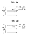
- the switch 160 is set to OFF-state, the S-phase and the ground (GNG) are separated from each other as shown in Fig. 8B , and thus AC power and the serial signal are separately transmitted as separate signals.
- the signal transmitted through the communication lines SG1, SG2 is received by the photocoupler 293.
- step S11 the controller 100 instructs the transmission circuit 110 to start the communication.
- the data supplied from the controller 100 are amplified by the transistors 111, 113 constituting the transmission circuit 110, and the amplified data are supplied to the photocoupler 115.
- the photocoupler 115 emits light from the built-in LED in accordance with the collector current of the transistor 113 and outputs the voltage corresponding to the intensity of the emitted light from the built-in photodiode.
- the output of the photodiode 115 is supplied to the transistor 118.
- the power (for example, 24V) from the transformer 191 is supplied to the transistor 118, and the transistor 118 switches the power supply voltage in accordance with the output of the photocoupler 115 and outputs it to the resistors 130, 140.
- the signal output from the resistors 130, 140 is supplied through the communication lines SG1, SG2 to the indoor units 20-1 to 20-n as shown in Fig. 2 .
- the indoor unit 20-1 receiving the signal as described above noise contained in the serial signal is removed by the noise filter 211, and the noise-removed serial signal is amplified by the bridge diode 212 and then applied to the resistors 230, 240.
- the voltage appearing at the resistor 240 is waveform-shaped by the zener diode 291, and then supplied through the resistor 292 to the photocoupler 293.
- the photocoupler 293 outputs the voltage corresponding to the voltage supplied through the resistor 292, and supplies the voltage concerned to the transistor 295.
- the transistor 295 inverts the output voltage of the photocoupler 293 and supplies the inverted output voltage to the controller 310.
- the controller 310 receiving the communication signal recognizes that the signal from the outdoor unit 10 is received, and an acknowledge signal thereto is output to the transistor 278.
- the transistors 278, 276 amplify the output of the controller 310 and supplies the amplified output to the photocoupler 274.
- the voltage corresponding to the collector current of the transistor 276 is output from the photocoupler 274, and supplied to the transistor 271.
- the transistor 271 outputs the output voltage corresponding to the output of the photocoupler 274 to the resistors 230, 240.
- the voltage appearing at the resistors 230, 240 is transmitted to the outdoor unit 10 through the communication lines SG1, SG2.
- the above operation is independently executed in each indoor unit.
- the controller of each indoor unit monitors the state of the communication lines SG1, SG2 by the reception circuit, and it transmits an acknowledge signal after it is checked that no signal is transmitted on the communication lines SG1, SG2. Accordingly, signal collision on the communication lines SG1, SG2 can be avoided.
- the signal transmitted from the indoor unit 20-1 is transmitted through the communication lines SG1, SG2 to the outdoor unit 10.
- the voltage supplied from the communication lines SG1, SG2 appear at the resistors 130, 140.
- the voltage (reception signal) appearing at the resistor 140 is waveform-shaped by the zener diode 126, and then supplied to the photocoupler 124 through the resistor 125.
- the output corresponding to the voltage appearing at the resistor 140 occurs at the output side of the photocoupler 124, and the transistor 122 inverts and amplifies the output voltage and supplies it to the controller 100.
- the controller 100 receives the output voltage of the transistor 122, and returns it to the original data, thereby recognizing that there is an acknowledge from the indoor unit 20-1.
- the switch 160 is set to OFF-state in Fig. 5 .
- the ground side of the transmission circuit 110 and the reception circuit 120 are set to Open-state, so that the outdoor unit 10 is set not to be connected to the indoor units 21-1 to 21-n through the communication lines. Therefore, the outdoor unit cannot communicate with the indoor units 21-1 to 21-n. Accordingly, in such a case, even when the outdoor unit 10 start the communication, no response (acknowledge) is transmitted from the indoor units 21-1 to 21-n.
- step S11 when the communication is started in step S11, an acknowledge is transmitted from the indoor units 20-1 to 20-n if the connection style of Fig. 1A is adopted.
- step S12 when the connection style of Fig. 1A is adopted, it is judged that there is an acknowledge (step S12; Yes), and the processing goes to step S13.
- step S12; No When the connection style of Fig. 1B is adopted, it is judged that there is no acknowledge (step S12; No) , and the processing goes to step S14.
- step S13 the controller 100 judges that the 4-wire type communication is adopted, and it keeps the switch 160 to OFF-state and finishes the processing. That is, the controller 100 judges that the connection style shown in Fig. 1A is adopted, and keeps the switch 160 to OFF-state.
- step S12 the processing goes to step S14, and the controller 100 sets the switch 150 to ON-state.
- the ground of the transmission circuit 110 and the reception circuit 120 and the S-phase of the power supply are set to be connected to each other.
- the switch 160 when the switch 160 is set to ON-state, the S-phase and the ground (GND) are set to be connected to each other, and thus AC power and the serial signal are superposed and output as shown in Fig. 8C .
- Fig. 9B the signal transmitted through the communication line SG and the power supply line S1 is received by the photocoupler 303.
- step S15 the controller 100 instructs the transmission circuit 110 to start the communication.
- the data supplied from the controller 100 are amplified by the transistors 111, 113 constituting the transmission circuit 110, and supplied to the photocoupler 115.
- the photocoupler 115 emits light from the built-in LED in accordance with the collector current of the transistor 113 and outputs the voltage corresponding to the intensity of the light from the built-in photodiode.
- the output of the photocoupler 115 is supplied to the transistor 118.
- the power from the transformer 191 is supplied to the transistor 118, and the transistor 118 switches the power source voltage in accordance with the output of the photocoupler 115 and outputs it to the resistors 130, 140.
- the signal output from the resistors 130, 140 is supplied to the indoor unit 21-1 to 21-n through the communication line SG and the power supply line S1.
- the indoor unit 21-1 receiving such a signal the reception signal is rectified by the diodes 221, 222, and the obtained signal is applied to the resistors 250, 260.
- the voltage appearing at the resistor 260 is waveform-shaped by the zener diode 301, and then supplied through the resistor 302 to the photocoupler 303.
- the photocoupler 303 outputs the voltage corresponding to the voltage supplied through the resistor 302, and supplies it to the transistor 305.
- the transistor 305 inverts and amplifies the output voltage of the photocoupler 303, and supplies it to the controller 310.
- the controller 310 received the serial signal recognizes that the signal from the outdoor unit 10 is received, and outputs an acknowledge signal thereto to the transistor 288.
- the transistors 288, 286 amplify the output of the controller 310, and supply it to the photocoupler 284.
- the voltage corresponding to the collector current of the transistor 286 is output from the photocoupler 284, and supplied to the transistor 281.
- the transistor 281 outputs the output voltage corresponding to the output of the photocoupler 284 to the resistors 250, 260.
- the voltage appearing at the resistors 250, 260 is transmitted through the communication line SG and the power supply line S1 to the outdoor unit 10.
- the above operation is executed independently in each indoor unit.
- the controller of each indoor unit monitors the state of the communication line SG and the power supply line S1 by the reception circuit, and transmits an acknowledge after it is checked that no signal is transmitted onto the communication line SG and the power supply line S1. Accordingly, signal collision on the communication line SG and the power supply line S1 is avoided.
- the signal transmitted from the indoor unit 21-1 is transmitted to the outdoor unit 10 through the communication line SG and the power supply line S1.
- the voltage supplied from the communication line SG and the power supply line S1 appear at the resistors 130, 140.
- the voltage appearing at the resistor 140 (the reception signal) is waveform-shaped by the zener diode 126, and then supplied to the photocoupler 124 through the resistor 125.
- the output corresponding to the voltage appearing at the resistor 140 occurs at the output side of the photocoupler 124, and the transistor 122 inverts and amplifies this output voltage and supplies it to the controller 100.
- the controller 100 receives the output voltage of the transistor 122, and restores it to the original data, thereby recognizing that there is an acknowledge from the indoor unit 21-1.
- step S12 when the connection style of Fig. 1A is adopted, it is judged in step S12 that there is an acknowledge, and thus the processing of the step S14 and subsequent steps are not executed.
- step S16 if there is an acknowledge from the indoor unit (step S16; Yes), the processing goes to step S17. If there is no acknowledge (step S16; No), the processing goes to step S18. For example, when the connection style of Fig. 1B is adopted, an acknowledge is transmitted from the indoor unit, and thus the processing goes to step S17.
- step S17 the controller 100 judges that the 3-wire type communication is adopted, and keeps the switch 160 to ON-state. Accordingly, the outdoor unit 10 and the indoor units 21-1 to 21-n are kept to a communication-possible state.
- step S18 the controller 100 judges a communication error because the communication is impossible by neither the 4-wire type communication nor the 3-wire type communication and thus wiring miss is assumed, for example, and thus the controller 100 finishes the processing.
- LED not shown
- the controller 100 judges a communication error because the communication is impossible by neither the 4-wire type communication nor the 3-wire type communication and thus wiring miss is assumed, for example, and thus the controller 100 finishes the processing.
- LED not shown
- the controller 100 judges a communication error because the communication is impossible by neither the 4-wire type communication nor the 3-wire type communication and thus wiring miss is assumed, for example, and thus the controller 100 finishes the processing.
- LED not shown
- the outdoor unit 10 can automatically identify the communication system of the indoor unit, and set the switch 160 to ON-state or OFF-state on the basis of the identification result. Accordingly, the outdoor unit can be replaced or added irrespective of the type of the exiting indoor units. Therefore, the choice of the machine type is increased.
- the installation technician can shorten the time required for the setting because the outdoor unit 10 automatically selects the proper communication system insofar as wiring is accurately performed. Furthermore, even when communication cannot be performed by using any communication system, occurrence of a communication error is notified to the installation technician. Therefore, the installation technician can rapidly know that the communication cannot be performed due to faulty wiring.
- the ground of the transmission circuit 110 and the ground of the reception circuit 120 are connected to the power supply line, so that the transmission and reception operation can be stably performed.
- the switch 160 is provided at the front stage of the noise filter 170, so that the serial signal can be prevented from being attenuated by the noise filter 170. Accordingly, stably communication can be performed.
- the switch 160 is first set to OFF-state to detect the communication system.
- the communication system is detected under the state that the switch 160 is set to ON-state, there is a case where communication is possible even when the outdoor unit and the indoor units are connected by the 4-wire type communication. Therefore, there is a case where the switch 150 is erroneously set to ON-state. That is, in the case of the 4-wire type, the communication lines SG1, SG2 are connected to the indoor units 20-1 to 20-n irrespective of the state of the switch 160, and thus communication may be possible.
- the detection is first performed under the state that the switch is set to OFF-state, so that the erroneous detection as described above can be prevented.
- Figs. 10 and 11 are block diagrams showing the construction of the second embodiment of the present invention.
- the second embodiment is different from the first embodiment in the construction of the indoor unit.
- the other construction of the second embodiment is the same as the first embodiment.
- the indoor unit 22-1 of the second embodiment has both of the 4-wire type communication circuit (the transmission circuit 270, the reception circuit 290, etc.) and the 3-wire type communication circuit (the transmission circuit 280, the reception circuit 300, etc.), and any communication system can be selected in accordance with the method for the wiring between the outdoor unit and the indoor unit. That is, any one of the 4-wire type and the 3-wire type can be selected by selecting any one of the wiring style shown in Fig. 1A or the wiring style shown in Fig. 1B .
- the indoor unit 22-1 mainly comprises a terminal table 202, rectifying circuits 210, 220, resistors 230 to 260, transmission circuits 270, 280, reception circuits 290, 300, a controller 310, a noise filter 320 and a load 330.
- the corresponding parts to those of Figs. 2 and 5 are represented by the same reference numerals, and thus the detailed description of the respective constituent elements is omitted.
- SG1 of the terminal table 150 and SG1 of the terminal table 202 are connected to each other, and SG2 of the terminal table 150 and SG2 of the terminal table 202 are connected to each other, whereby the 4-wire type communication is selected.
- SG1 of the terminal table and SG of the terminal table 202 are connected to each other, and SG2 of the terminal table 150 is set to an open state.
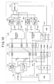
- Fig. 12 is a circuit diagram showing the detailed construction of the indoor unit 22-1 shown in Figs. 10 and 11 .
- the corresponding parts to those of Figs. 4 and 6 are represented by the same reference numerals, and the detailed description thereof is omitted.
- the transistor 288 shown in Fig. 6 and the resistor 287 are omitted, and the transistor 278 and the resistor 277 are commonly used.
- the resistor 306 shown in Fig. 6 is omitted, and the resistor 296 is commonly used.
- the terminal table 202 is newly provided in place of the terminal tables 200, 201. With respect to the terminal table 202, the communication lines SG1, SG2 and SG are connectable, and the power supply lines S1,R1 are connectable.
- the other construction is the same as those of Figs. 4 and 6 .
- an outdoor unit and an indoor unit are additionally provided under the state that an indoor unit and wiring exist or a case where an outdoor unit and an indoor unit are additionally provided under the state that wiring exists. More specifically, for example, an outdoor unit and an indoor unit are additionally provided under the state that the wiring shown in Fig. 1A or Fig. 1B has already existed, or an outdoor unit and an indoor unit are additionally provided under the state that the wiring and the indoor units shown in Fig. 1A or Fig. 1B have already existed.
- the installation technician connects the outdoor unit 10 and the indoor unit 22-1 by the wiring method shown in Fig. 10 . That is, SG1, SG2 of the terminal table 150 are connected to SG1, SG2 of the terminal table 202, and also S1, R1 of the terminal table 150 are connected to S1, R1 of the terminal table 202.
- the installation technician connects the outdoor unit 10 and the indoor unit 22-1 by the wiring shown in Fig. 11 . That is, SG1 of the terminal table 150 is connected to SG of the terminal table 202, and S1, R1 of the terminal table 150 are connected to S1, R1 of the terminal table 202.
- the installation technician turns on the power of the outdoor unit 10.
- the power supply to the respective parts of the outdoor unit 10 is started, and also the power supply to the respective indoor units is started through the power supply lines S1, R1.
- the controller 100 of the outdoor unit 10 executes the processing shown in Fig. 7 .
- step S12 the communication is executed between the transmission circuit 270 and the reception circuit 290 in step S11, and thus "Yes” is judged in step S12. Accordingly, the processing goes to step S13 to fix the switch 160 to OFF-state and select the 4-wire type communication. Furthermore, when the connection style shown in Fig. 11 is adopted, the communication is executed between the transmission circuit 280 and the reception circuit 200 in step S15, and thus "Yes” is judged in step S16. Therefore, the processing goes to step S17 to fix the switch 160 to ON-state and select the 3-wire type communication. As a result, the communication can be normally executed between the indoor units and the outdoor unit irrespective of the state of the existing facilities.
- both the 4-wire type communication circuit and the 3-wire type communication circuit are provided for the indoor units. Therefore, a new indoor unit can be additionally provided or replaced irrespective of whether the existing facilities adopt the 4-wire type communication or the 3-wire type communication.
- the outdoor unit 10 automatically recognizes which one of the 4-wire type and the 3-wire type is selected, and sets the switch 160 to ON-state or OFF-state on the basis of the recognition result through the above processing, whereby the load of the installation technician can be reduced.
- the switch 160 is first set to OFF-state and the communication style is detected by the processing shown in Fig. 7 . Therefore, error detection can be prevented as described above.
- circuit constructions shown in Figs. 3 , 4 , 6 , 12 are examples, and other circuit constructions may be adopted.
- the switch 160 is the electromagnetic relay. However, a semiconductor switch or the like may be used. Furthermore, in the above-described embodiments, the switch 160 is connected to the S-phase. However, the switch 160 may be connected to the other phases (for example, R-phase). Still furthermore, the noise filter 170 may be omitted.
- the switch 160 is automatically set.
- the switch 160 may be a manual switch so that the installation technician can manually set the switch 160.
- the manual switch is set to ON-state, and when the 4-wire type is selected, the manual switch is set to Off-state.
- the air conditioning system is constructed by the outdoor unit 10 and the indoor units 20-1 to 20-n, the indoor units 21-1 to 21-n or the indoor units 22-1 to 22-n.
- a central control unit and an interface device may be added as occasion demands.
- the number of indoor units may be one or more.
- the outdoor unit 10 is provided with the function of automatically detecting the communication system by the switch 160.
- the indoor unit 22-1 shown in Figs. 10 , 11 may be connected to an outdoor unit which does not have the above function.
- the wiring method shown in Fig. 10 may be adopted.
- the wiring method shown in Fig. 11 may be adopted.
- an indoor unit can be additionally provided or replaced irrespective of the type of the existing outdoor unit.
Landscapes
- Engineering & Computer Science (AREA)
- Chemical & Material Sciences (AREA)
- Combustion & Propulsion (AREA)
- Mechanical Engineering (AREA)
- General Engineering & Computer Science (AREA)
- Physics & Mathematics (AREA)
- Fuzzy Systems (AREA)
- Mathematical Physics (AREA)
- Signal Processing (AREA)
- Air Conditioning Control Device (AREA)
- Cable Transmission Systems, Equalization Of Radio And Reduction Of Echo (AREA)
Applications Claiming Priority (1)
| Application Number | Priority Date | Filing Date | Title |
|---|---|---|---|
| JP2007248464A JP4874202B2 (ja) | 2007-09-26 | 2007-09-26 | 空気調和システムおよび室外機 |
Publications (3)
| Publication Number | Publication Date |
|---|---|
| EP2042818A2 true EP2042818A2 (de) | 2009-04-01 |
| EP2042818A3 EP2042818A3 (de) | 2012-04-25 |
| EP2042818B1 EP2042818B1 (de) | 2013-07-24 |
Family
ID=40129916
Family Applications (1)
| Application Number | Title | Priority Date | Filing Date |
|---|---|---|---|
| EP20080016779 Not-in-force EP2042818B1 (de) | 2007-09-26 | 2008-09-24 | Klimaanlagensystem mit mehreren Datenverbindungsleitungen zwischen Innen- und Ausseneinheit und Schalteinrichtung für diese Verbindungen |
Country Status (6)
| Country | Link |
|---|---|
| US (1) | US8205466B2 (de) |
| EP (1) | EP2042818B1 (de) |
| JP (1) | JP4874202B2 (de) |
| KR (1) | KR101134914B1 (de) |
| CN (1) | CN101398204B (de) |
| ES (1) | ES2429789T3 (de) |
Cited By (3)
| Publication number | Priority date | Publication date | Assignee | Title |
|---|---|---|---|---|
| EP2392869A3 (de) * | 2010-06-01 | 2014-01-15 | Mitsubishi Electric Corporation | Klimaanlage |
| EP2416080A3 (de) * | 2010-08-05 | 2017-02-01 | Samsung Electronics Co., Ltd. | Elektrische Vorrichtung und Sicherheitssteuerungsverfahren dafür |
| EP2679925A4 (de) * | 2011-02-21 | 2018-07-11 | Mitsubishi Electric Corporation | Klimatisierungsvorrichtung und klimaanlage |
Families Citing this family (7)
| Publication number | Priority date | Publication date | Assignee | Title |
|---|---|---|---|---|
| JP5340574B2 (ja) * | 2007-09-26 | 2013-11-13 | 三洋電機株式会社 | 空気調和システムおよび通信制御装置 |
| JP5382105B2 (ja) * | 2011-12-28 | 2014-01-08 | ダイキン工業株式会社 | 空気調和装置 |
| ES2949446T3 (es) * | 2018-03-01 | 2023-09-28 | Daikin Ind Ltd | Sistema de acondicionamiento de aire |
| US11781776B2 (en) * | 2018-04-18 | 2023-10-10 | Mitsubishi Electric Corporation | Control substrate and indoor equipment of air conditioner |
| CN108895617B (zh) * | 2018-05-17 | 2024-01-23 | 广东美的制冷设备有限公司 | 空调器系统和空调器系统的通信方法 |
| CN109282461B (zh) * | 2018-10-09 | 2021-05-28 | 青岛海信日立空调系统有限公司 | 空调机组的控制方法、空调交换机以及空调机组 |
| CN111397161B (zh) * | 2020-03-16 | 2022-01-18 | 珠海格力电器股份有限公司 | 一种空调内机编号确定方法、装置、存储介质及空调 |
Citations (1)
| Publication number | Priority date | Publication date | Assignee | Title |
|---|---|---|---|---|
| JPH08303842A (ja) | 1995-05-09 | 1996-11-22 | Sanyo Electric Co Ltd | エアコンの制御方法 |
Family Cites Families (20)
| Publication number | Priority date | Publication date | Assignee | Title |
|---|---|---|---|---|
| US3959979A (en) * | 1971-12-06 | 1976-06-01 | Kramer Daniel E | Dual voltage forced air heat exchanger |
| JPS63161347A (ja) * | 1986-12-25 | 1988-07-05 | Toshiba Corp | 空気調和機の室内側ユニツト |
| US5457621A (en) * | 1992-02-21 | 1995-10-10 | Abb Power T&D Company Inc. | Switching power supply having voltage blocking clamp |
| JP3214110B2 (ja) * | 1992-11-13 | 2001-10-02 | 松下電器産業株式会社 | 空気調和機の室内外通信制御装置 |
| JP2859066B2 (ja) * | 1993-01-22 | 1999-02-17 | 三洋電機株式会社 | 空気調和機 |
| JP3076688B2 (ja) * | 1993-03-08 | 2000-08-14 | 松下冷機株式会社 | 空気調和機の制御装置 |
| JPH06313609A (ja) * | 1993-04-28 | 1994-11-08 | Sanyo Electric Co Ltd | 空気調和機 |
| JP2948502B2 (ja) * | 1995-03-30 | 1999-09-13 | 三菱電機株式会社 | マルチ式空気調和機の運転制御装置 |
| US5737168A (en) * | 1995-05-04 | 1998-04-07 | Baker; George T. | Electrical power management system |
| JP3434098B2 (ja) * | 1995-09-29 | 2003-08-04 | 三菱重工業株式会社 | 双方向信号転送回路の保護装置 |
| JP3297690B2 (ja) * | 1996-02-21 | 2002-07-02 | シャープ株式会社 | 端子台及びそれを備えた空気調和機 |
| JP3549038B2 (ja) * | 1996-08-27 | 2004-08-04 | ヤンマー株式会社 | エンジンヒートポンプの室外機のコントロールユニット |
| DE19823641A1 (de) * | 1998-05-27 | 2000-02-10 | Bosch Gmbh Robert | Zünder für eine Gasentladungslampe, insbesondere Hochdruck-Gasentladungslampe für Kraftfahrzeugscheinwerfer |
| SG91835A1 (en) * | 1999-02-26 | 2002-10-15 | Lg Electronics Inc | Communication module and initialization method for multi-air conditioner system |
| US6603221B1 (en) * | 1999-04-22 | 2003-08-05 | Zhongdu Liu | Solid state electrical switch |
| JP4110510B2 (ja) * | 2002-03-08 | 2008-07-02 | 三菱電機株式会社 | 空気調和機の誤配線検出装置 |
| JP4129594B2 (ja) * | 2003-04-15 | 2008-08-06 | 株式会社日立製作所 | 空調システム |
| JP2005106295A (ja) * | 2003-08-05 | 2005-04-21 | Mitsubishi Electric Corp | 空気調和機の配線接続構造 |
| JP3815463B2 (ja) * | 2003-08-27 | 2006-08-30 | 松下電器産業株式会社 | 分離型空気調和機 |
| JP4725119B2 (ja) * | 2004-02-10 | 2011-07-13 | 株式会社富士通ゼネラル | 空気調和機の制御装置 |
-
2007
- 2007-09-26 JP JP2007248464A patent/JP4874202B2/ja not_active Expired - Fee Related
-
2008
- 2008-05-16 CN CN2008101002155A patent/CN101398204B/zh not_active Expired - Fee Related
- 2008-06-18 KR KR1020080057316A patent/KR101134914B1/ko not_active Expired - Fee Related
- 2008-09-24 ES ES08016779T patent/ES2429789T3/es active Active
- 2008-09-24 EP EP20080016779 patent/EP2042818B1/de not_active Not-in-force
- 2008-09-26 US US12/239,216 patent/US8205466B2/en not_active Expired - Fee Related
Patent Citations (1)
| Publication number | Priority date | Publication date | Assignee | Title |
|---|---|---|---|---|
| JPH08303842A (ja) | 1995-05-09 | 1996-11-22 | Sanyo Electric Co Ltd | エアコンの制御方法 |
Cited By (3)
| Publication number | Priority date | Publication date | Assignee | Title |
|---|---|---|---|---|
| EP2392869A3 (de) * | 2010-06-01 | 2014-01-15 | Mitsubishi Electric Corporation | Klimaanlage |
| EP2416080A3 (de) * | 2010-08-05 | 2017-02-01 | Samsung Electronics Co., Ltd. | Elektrische Vorrichtung und Sicherheitssteuerungsverfahren dafür |
| EP2679925A4 (de) * | 2011-02-21 | 2018-07-11 | Mitsubishi Electric Corporation | Klimatisierungsvorrichtung und klimaanlage |
Also Published As
| Publication number | Publication date |
|---|---|
| KR20090031973A (ko) | 2009-03-31 |
| CN101398204B (zh) | 2011-01-26 |
| JP4874202B2 (ja) | 2012-02-15 |
| JP2009079810A (ja) | 2009-04-16 |
| CN101398204A (zh) | 2009-04-01 |
| KR101134914B1 (ko) | 2012-04-17 |
| EP2042818A3 (de) | 2012-04-25 |
| US8205466B2 (en) | 2012-06-26 |
| ES2429789T3 (es) | 2013-11-15 |
| EP2042818B1 (de) | 2013-07-24 |
| US20090077989A1 (en) | 2009-03-26 |
Similar Documents
| Publication | Publication Date | Title |
|---|---|---|
| EP2042818B1 (de) | Klimaanlagensystem mit mehreren Datenverbindungsleitungen zwischen Innen- und Ausseneinheit und Schalteinrichtung für diese Verbindungen | |
| EP2042815A2 (de) | Außenraumeinheit und Klimaanlagensystem damit | |
| EP2042819A2 (de) | Klimaanlagensystem mit Kontrolle der elektrischen Verbindung zwischen Innen- und Ausseneinheit | |
| US12578111B2 (en) | Heating, ventilation, and/or air conditioning system fault log management systems | |
| WO1996012917A1 (en) | Transmission device for air conditioner | |
| EP2746685A2 (de) | Klimaanlage | |
| WO1999034152A1 (en) | Indoor-outdoor communication device in air conditioner | |
| JP3206595B2 (ja) | 空気調和装置の伝送装置 | |
| CN101173814A (zh) | 空调系统的通信错误检测装置及其方法 | |
| US10082311B2 (en) | Device for controlling air conditioner | |
| JP2008249269A (ja) | 空気調和機 | |
| JP3018929B2 (ja) | 空気調和装置の伝送装置 | |
| JP5340574B2 (ja) | 空気調和システムおよび通信制御装置 | |
| EP0742636A2 (de) | Verbesserte Schnittstellenschaltung zum Gebrauch mit Multisplitklimaanlagesystemen | |
| KR100765168B1 (ko) | 멀티 시스템 공기 조화기의 오결선 보호 장치 및 그 제어방법 | |
| WO2024185037A1 (ja) | 欠相検出装置及び冷凍サイクル装置 | |
| JPH10234141A (ja) | 複数電気機器の接続状態探索方法及びその装置 | |
| JPH0634190A (ja) | 空気調和装置の運転制御装置 | |
| KR20180079743A (ko) | 멀티 디바이스 제어 장치 및 방법 | |
| JPH05248691A (ja) | 空気調和機 | |
| JPH062921A (ja) | 空気調和機 |
Legal Events
| Date | Code | Title | Description |
|---|---|---|---|
| PUAI | Public reference made under article 153(3) epc to a published international application that has entered the european phase |
Free format text: ORIGINAL CODE: 0009012 |
|
| 17P | Request for examination filed |
Effective date: 20080924 |
|
| AK | Designated contracting states |
Kind code of ref document: A2 Designated state(s): AT BE BG CH CY CZ DE DK EE ES FI FR GB GR HR HU IE IS IT LI LT LU LV MC MT NL NO PL PT RO SE SI SK TR |
|
| AX | Request for extension of the european patent |
Extension state: AL BA MK RS |
|
| PUAL | Search report despatched |
Free format text: ORIGINAL CODE: 0009013 |
|
| AK | Designated contracting states |
Kind code of ref document: A3 Designated state(s): AT BE BG CH CY CZ DE DK EE ES FI FR GB GR HR HU IE IS IT LI LT LU LV MC MT NL NO PL PT RO SE SI SK TR |
|
| AX | Request for extension of the european patent |
Extension state: AL BA MK RS |
|
| RIC1 | Information provided on ipc code assigned before grant |
Ipc: F24F 1/00 20110101ALI20120316BHEP Ipc: F24F 11/02 20060101AFI20120316BHEP |
|
| REG | Reference to a national code |
Ref country code: DE Ref legal event code: R079 Ref document number: 602008026191 Country of ref document: DE Free format text: PREVIOUS MAIN CLASS: F24F0011020000 Ipc: F24F0001200000 |
|
| 17Q | First examination report despatched |
Effective date: 20121203 |
|
| AKX | Designation fees paid |
Designated state(s): DE ES FR GB HU IT |
|
| RIC1 | Information provided on ipc code assigned before grant |
Ipc: F24F 11/00 20060101ALI20121221BHEP Ipc: F24F 1/20 20110101AFI20121221BHEP |
|
| GRAP | Despatch of communication of intention to grant a patent |
Free format text: ORIGINAL CODE: EPIDOSNIGR1 |
|
| RAP1 | Party data changed (applicant data changed or rights of an application transferred) |
Owner name: SANYO ELECTRIC CO., LTD. |
|
| INTG | Intention to grant announced |
Effective date: 20130325 |
|
| GRAS | Grant fee paid |
Free format text: ORIGINAL CODE: EPIDOSNIGR3 |
|
| GRAA | (expected) grant |
Free format text: ORIGINAL CODE: 0009210 |
|
| AK | Designated contracting states |
Kind code of ref document: B1 Designated state(s): DE ES FR GB HU IT |
|
| REG | Reference to a national code |
Ref country code: GB Ref legal event code: FG4D |
|
| REG | Reference to a national code |
Ref country code: DE Ref legal event code: R096 Ref document number: 602008026191 Country of ref document: DE Effective date: 20130919 |
|
| REG | Reference to a national code |
Ref country code: ES Ref legal event code: FG2A Ref document number: 2429789 Country of ref document: ES Kind code of ref document: T3 Effective date: 20131115 |
|
| PLBE | No opposition filed within time limit |
Free format text: ORIGINAL CODE: 0009261 |
|
| STAA | Information on the status of an ep patent application or granted ep patent |
Free format text: STATUS: NO OPPOSITION FILED WITHIN TIME LIMIT |
|
| 26N | No opposition filed |
Effective date: 20140425 |
|
| REG | Reference to a national code |
Ref country code: DE Ref legal event code: R097 Ref document number: 602008026191 Country of ref document: DE Effective date: 20140425 |
|
| PG25 | Lapsed in a contracting state [announced via postgrant information from national office to epo] |
Ref country code: HU Free format text: LAPSE BECAUSE OF FAILURE TO SUBMIT A TRANSLATION OF THE DESCRIPTION OR TO PAY THE FEE WITHIN THE PRESCRIBED TIME-LIMIT; INVALID AB INITIO Effective date: 20080924 |
|
| REG | Reference to a national code |
Ref country code: FR Ref legal event code: PLFP Year of fee payment: 9 |
|
| REG | Reference to a national code |
Ref country code: FR Ref legal event code: PLFP Year of fee payment: 10 |
|
| REG | Reference to a national code |
Ref country code: FR Ref legal event code: PLFP Year of fee payment: 11 |
|
| PGFP | Annual fee paid to national office [announced via postgrant information from national office to epo] |
Ref country code: IT Payment date: 20180925 Year of fee payment: 11 Ref country code: DE Payment date: 20180920 Year of fee payment: 11 Ref country code: FR Payment date: 20180925 Year of fee payment: 11 |
|
| PGFP | Annual fee paid to national office [announced via postgrant information from national office to epo] |
Ref country code: GB Payment date: 20180919 Year of fee payment: 11 |
|
| PGFP | Annual fee paid to national office [announced via postgrant information from national office to epo] |
Ref country code: ES Payment date: 20181022 Year of fee payment: 11 |
|
| REG | Reference to a national code |
Ref country code: DE Ref legal event code: R119 Ref document number: 602008026191 Country of ref document: DE |
|
| PG25 | Lapsed in a contracting state [announced via postgrant information from national office to epo] |
Ref country code: DE Free format text: LAPSE BECAUSE OF NON-PAYMENT OF DUE FEES Effective date: 20200401 |
|
| PG25 | Lapsed in a contracting state [announced via postgrant information from national office to epo] |
Ref country code: IT Free format text: LAPSE BECAUSE OF NON-PAYMENT OF DUE FEES Effective date: 20190924 |
|
| GBPC | Gb: european patent ceased through non-payment of renewal fee |
Effective date: 20190924 |
|
| PG25 | Lapsed in a contracting state [announced via postgrant information from national office to epo] |
Ref country code: GB Free format text: LAPSE BECAUSE OF NON-PAYMENT OF DUE FEES Effective date: 20190924 Ref country code: FR Free format text: LAPSE BECAUSE OF NON-PAYMENT OF DUE FEES Effective date: 20190930 |
|
| REG | Reference to a national code |
Ref country code: ES Ref legal event code: FD2A Effective date: 20210129 |
|
| PG25 | Lapsed in a contracting state [announced via postgrant information from national office to epo] |
Ref country code: ES Free format text: LAPSE BECAUSE OF NON-PAYMENT OF DUE FEES Effective date: 20190925 |