EP2042837A1 - Dispositif de compteur pour communiquer sur une ligne de communication - Google Patents
Dispositif de compteur pour communiquer sur une ligne de communication Download PDFInfo
- Publication number
- EP2042837A1 EP2042837A1 EP07117213A EP07117213A EP2042837A1 EP 2042837 A1 EP2042837 A1 EP 2042837A1 EP 07117213 A EP07117213 A EP 07117213A EP 07117213 A EP07117213 A EP 07117213A EP 2042837 A1 EP2042837 A1 EP 2042837A1
- Authority
- EP
- European Patent Office
- Prior art keywords
- meter device
- signal
- communication line
- meter
- request
- Prior art date
- Legal status (The legal status is an assumption and is not a legal conclusion. Google has not performed a legal analysis and makes no representation as to the accuracy of the status listed.)
- Granted
Links
Images


Classifications
-
- G—PHYSICS
- G01—MEASURING; TESTING
- G01D—MEASURING NOT SPECIALLY ADAPTED FOR A SPECIFIC VARIABLE; ARRANGEMENTS FOR MEASURING TWO OR MORE VARIABLES NOT COVERED IN A SINGLE OTHER SUBCLASS; TARIFF METERING APPARATUS; MEASURING OR TESTING NOT OTHERWISE PROVIDED FOR
- G01D18/00—Testing or calibrating apparatus or arrangements provided for in groups G01D1/00 - G01D15/00
-
- G—PHYSICS
- G01—MEASURING; TESTING
- G01D—MEASURING NOT SPECIALLY ADAPTED FOR A SPECIFIC VARIABLE; ARRANGEMENTS FOR MEASURING TWO OR MORE VARIABLES NOT COVERED IN A SINGLE OTHER SUBCLASS; TARIFF METERING APPARATUS; MEASURING OR TESTING NOT OTHERWISE PROVIDED FOR
- G01D4/00—Tariff metering apparatus
- G01D4/002—Remote reading of utility meters
-
- G—PHYSICS
- G01—MEASURING; TESTING
- G01F—MEASURING VOLUME, VOLUME FLOW, MASS FLOW OR LIQUID LEVEL; METERING BY VOLUME
- G01F15/00—Details of, or accessories for, apparatus of groups G01F1/00 - G01F13/00 insofar as such details or appliances are not adapted to particular types of such apparatus
- G01F15/06—Indicating or recording devices
- G01F15/061—Indicating or recording devices for remote indication
- G01F15/063—Indicating or recording devices for remote indication using electrical means
-
- G—PHYSICS
- G01—MEASURING; TESTING
- G01F—MEASURING VOLUME, VOLUME FLOW, MASS FLOW OR LIQUID LEVEL; METERING BY VOLUME
- G01F15/00—Details of, or accessories for, apparatus of groups G01F1/00 - G01F13/00 insofar as such details or appliances are not adapted to particular types of such apparatus
- G01F15/06—Indicating or recording devices
- G01F15/068—Indicating or recording devices with electrical means
-
- G—PHYSICS
- G01—MEASURING; TESTING
- G01K—MEASURING TEMPERATURE; MEASURING QUANTITY OF HEAT; THERMALLY-SENSITIVE ELEMENTS NOT OTHERWISE PROVIDED FOR
- G01K1/00—Details of thermometers not specially adapted for particular types of thermometer
- G01K1/02—Means for indicating or recording specially adapted for thermometers
Definitions
- the invention relates to the field of meter devices, especially to the field of electronic meter devices, more specifically to the field of meter devices for consumption metering purposes.
- Heat meter systems with a heat calculator connected to a flow meter and two temperature sensors are well-known. According to standardized methods, a flow meter normally sends a train of pulses representing a measured flow rate, e.g. one pulse pr. 0.1 litre of liquid etc. This quantity signal can be sent using a one-wire connection between flow meter and heat calculator.
- additional functionalities in intelligent meter systems can profit from an additional communication between the heat calculator and the flow meter, e.g. 2-way communication.
- additional data that can be sent from the flow meter to the heat calculator are: 1) a temperature derived by or directly measured by the flow meter, 2) an error status of the flow meter, 3) different internal parameters and variables of the flow meter, and 4) an identification code of the flow meter to be used for self-configuration.
- Examples of data that can be sent from the heat calculator to the flow meter are: 1) configuration data (such as volume per pulse), 2) a cut-off command, and 3) adjustment data for adjustment or calibration of the flow meter.
- such additional communication between flow meter and heat calculator can be performed automatically, e.g. controlled by the heat calculator, without the need for any manual actions by an operator. Further, in order to lower manufacturing costs and the probability of installation errors, it is desired that such extra communication can be performed without the need for any additional wiring between flow meter and heat calculator.
- a meter device e.g. a flow meter
- a flow meter capable of communicating additional data on existing communication lines, i.e. data apart from the primary physical quantity data measured by the meter.
- the meter device must be able to communicate the additional data without manual interaction by an operator.
- the invention provides a meter device arranged to measure a physical quantity, the meter device including:
- Such meter device is advantageous for a number of metering systems, e.g. where it is desired to communicate extra data between the meter device and a calculator unit.
- the meter is suitable for systems where first communication line is a one-wire connection, such as in existing heat meter systems where a single wire interconnect a flow meter and a heat calculator. Since the meter device can stop sending the physical quantity signal, e.g. flow rate signal, the communication line is cleared for alternative communication between the meter device and external unit such as a heat calculator.
- the meter device can switch between two modes of operation, namely:
- the request signal may have different forms.
- the meter device is arranged to detect a request signal being a signal with a constant level of a predetermined duration, preferably such that the predetermined duration being such that it exceeds a duration of a quantity signal pulse sent by the meter device, such as a predetermined duration being more than twice the duration of the quantity signal pulse duration.
- the request signal may alternatively be a series of very short pulses closely spaced in time, such as that the pulses can easily be discriminated from quantity signal pulses sent by the meter device.
- the additional communication with the meter device may include data to or from the flow meter than should normally not be available by unauthorized persons.
- the additional communication may include configuration or calibration commands such as a command causing the meter device to change its quantity signal pulse rate, or such as a command changing an internal calibration coefficient in the meter device, or such as a cut-off command causing the meter device to simply abort measuring.
- a restriction may be implemented by a software code or a password protection to be sent via the communication line CL in case such restricted communication is intended.
- code or password protection may be implemented according to techniques known by the skilled person.
- a restriction may be implemented in hardware, such as requiring a manual interaction to switch the meter device to a "restricted communication mode".
- This may be implemented as a user operable switch or jumper hidden behind a lid or the like, such that it is not possible to gain access to the switch or jumper without breaking a certification seal.
- the switch or jumper function may alternatively be obtained by short circuiting two hidden electrical terminals, thereby enabling "restricted communication mode”.
- access to the "restricted communication mode” may be accessed via a wireless receiver in the meter device that can receive a wireless key signal from a dedicated wireless key device, e.g. based on bluetooth technology.
- the communication line is a one-wire communication line.
- One-wire embodiments are suitable for modification of existing meter devices since 2-way communication becomes possible without any change in the existing physical interconnection of meter device and associated equipment.
- electric interface of the meter device and associated equipment must be suited for the expanded communication possibilities, as will be described later.
- the processor controlling the function of the meter device must of course be suited for the desired type of communication.
- the meter device may be a flow meter, e.g. an ultrasonic flow meter, an electric energy meter, or a meter device arranged for other types of measurements involving physical quantity data and communication of such data.
- a flow meter e.g. an ultrasonic flow meter, an electric energy meter, or a meter device arranged for other types of measurements involving physical quantity data and communication of such data.
- the invention provides a meter system including
- a meter device being a flow meter forming part of a heat meter
- the principles described below apply as well for any meter device, e.g. a meter device of an electric energy meter system etc.
- Fig. 1 illustrates prior art one-way communication between output of a flow meter and input of a heat calculator.
- the flow meter includes a pulse generator Fo arranged to generate a quantity signal QS in the form of a pulse train representing a measured liquid flow rate.
- the calculator includes a calculator input Ci arranged to receive pulse from the flow meter.
- the pulse generator Fo is connected to the calculator input Ci by a one-wire communication line CL.
- the pulse generator Fo can then generate pulses by switching the potential on the communication line CL, such as by switching between electrical ground and a fixed voltage potential.
- Fig. 2 illustrates a meter device embodiment according to the invention, e.g. a flow meter, an electric energy meter etc.
- the meter device has a measurement unit M arranged to receive a measurement input Mi and perform a measurement thereon.
- the measurement unit M is connected to a processor P that receives data from the measurement unit M and calculates based thereon a value representing a physical quantity reflecting the measurement input Mi.
- Data representing the physical quantity is communicated, preferably via a one-wire communication line CL, as a quantity signal QS, e.g. in the form of a pulse train such as according to known standards for meter devices.
- the meter device further includes a request detector Fi connected to the communication line CL and arranged to detect a request signal SIR received via the communication line CL.
- the quantity signal generator Fo must be capable of accepting an external device sending a signal on the communication line CL at the same time it sends the quantity signal QS.
- the quantity signal generator Fo is connected to the communication line CL via a current limiting resistor Zo.
- the meter device stops sending the quantity signal QS, and the meter device is thereby prepared for utilizing the communication line CL for additional communication with the external device that sent the request signal SIR.
- the processor P serves to the control the overall operation of the meter device, and thus the processor P is connected to receive a signal, e.g. an interrupt, from the request detector Fi so as to be able to change mode of operation and stop the signal generator Fo in generating the quantity signal QS.
- the additional communication may be any two-way communication between the meter device and e.g. a calculator unit.
- the meter device is configured to send one type of data in response to the SIR signal, e.g. status data or a liquid temperature measured by the meter device in case it is a flow meter.
- the calculator unit may use the SIR signal merely to cause the meter device to clear the communication line CL and then send a command or specific request in the additional communication part.
- the additional communication may include a configuration request from the calculator unit requesting e.g. calibration data from the flow meter in order to enable the calculator to adjust its calculation algorithm to an unknown meter device connected thereto. E.g.
- a flow meter may respond to the request by sending data representing e.g. which liquid quantity pr. pulse is represented in its quantity signal QS.
- the meter device may receive a configuration command, such as data informing the meter device which quantity signal is expected from the calculator unit, so as to enable the meter device to configure its quantity signal QS accordingly.
- configuration data and/or adjustment data, and/or a cut-off command may be sent from the calculator unit to the meter device.
- the additional communication can be terminated in several ways.
- the meter device may be programmed to re-enter the normal pulse generation mode after expiration of a predetermined timeout period.
- the calculator unit may send a command to cause the meter device to re-enter normal pulse generation mode.
- the meter device can have a mode control by means of a knob or switch arranged for manual selection of mode of operation.
- the calculator unit loses track on the measured quantity, e.g. liquid flow, since the quantity signal in this period is interrupted.
- the meter device is arranged to store data representing the quantity measured in this period, and then send data representing this quantity, e.g. liquid volume, as a quantity data signal, thereby enabling the calculator unit to calculate the correct physical quantity taking into account also the quantity corresponding to the period where the normal quantity signal QS has been stopped.
- This quantity data signal can be sent by the meter device in several ways, either as sending data representing a single value automatically upon re-entering normal quantity signal mode, or upon specific request by the calculator unit. Further, the quantity data signal can be communicated by sending extra pulses corresponding to the number of pulses that would have been sent without the interruption caused by the SIR signal and the subsequent additional communication.
- Fig. 3 illustrates an example of a possible communication scheme between a meter device and a calculator unit, i.e. signal levels versus time, between a pulse generator Fo of the meter device and a request generator Co of a calculator unit interconnected by a communication line CL.
- the pulse generator Fo of the meter device Up to time t1 the pulse generator Fo of the meter device generates pulses on the communication line CL.
- the request generator Co of the calculator drags the communication line CL to a constant low level. If the period between t1 and t2 is longer than a predetermined period, this is detected by the meter device, as a request signal SIR. In the same period, between t1 and t2, the pulse generator Fo output tries to send a quantity signal pulse on the communication line CL.
- the meter device upon detection of the request signal SIR, the meter device stops the pulse generator Fo in sending further quantity pulses.
- the SIR signal has caused the meter device to change its mode of operation, since it has stopped sending its quantity signal and entered a communication mode, e.g. a mode in which it is capable of communicating according to normal serial communication schemes on the communication line CL.
- This additional communication is indicated in Fig. 3 to take place on the communication line CL after time t3.
- the additional communication may be any two-way communication between flow meter and heat calculator.
- the flow meter is configured to send one type of data in response to the SIR signal, e.g. status data or a liquid temperature measured by the flow meter.
- the heat calculator may use the SIR signal merely to cause the flow meter to clear the communication line CL and then send a command or specific request in the additional communication part.
- the additional communication part can be terminated in several ways.
- flow meter may be programmed to re-enter the normal pulse generation mode after expiration of a predetermined timeout period.
- the heat calculator may send a command to cause the flow meter to re-enter normal pulse generation mode.
- the flow meter can have a mode control by means of a knob or switch arranged for manual selection of mode of operation.
- the heat calculator loses track on the liquid flow rate since the flow rate signal is stopped.
- the flow meter is arranged to send data representing the amount of liquid volume measured in the period where the flow rate signal has been stopped, thereby enabling the heat calculator to calculate the correct amount of heat.
- This extra liquid volume can be sent by the flow meter in several ways, either as date representing a single value automatically upon re-entering normal pulse more, or upon specific request by the heat calculator. Further, the extra liquid volume can be communicated by sending extra pulses corresponding to the number of pulses that would have been sent without the interruption caused by the SIR signal and subsequent additional communication.
- Fig. 3 The timing scheme in Fig. 3 is illustrated for one choice of digital levels, however it is appreciated that the principles apply as well.
- the request signal SIR may be communicated by a high level (digital '1') instead of a low level (digital '0') as illustrated.
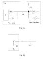
- Figs. 4 and 5 illustrate two possible implementations of a flow meter and associated heat calculator interconnected with a one-wire communication line CL.
- Figs. 4 and 5 illustrate two possible implementations of a flow meter and associated heat calculator interconnected with a one-wire communication line CL.
- Figs. 4 and 5 For clarity reasons, only parts of the flow meter and heat calculator related to contact with the communication line CL are shown in Figs. 4 and 5 . Other parts of the flow meter and heat calculator can be implemented such as known in the art, e.g. the flow meter may be an ultrasonic flow meter.
- the flow meter may be an ultrasonic flow meter.
- One common feature distinguishes both of the flow meter embodiments illustrated in Figs. 4 and 5 from prior art, namely the presence of a request detector Fi arranged to detect a request signal SIR on the communication line CL sent by a request generator Co in the heat calculator.
- the request detector Fi may be a simple sensor circuit connected to the communication line CL, as illustrated, and arranged to generate an interrupt signal to an internal processor in the flow meter upon detection of a request signal SIR on the communication line CL.
- the processor can then change its mode of operation in response to the interrupt, i.e. stop sending flow rate pulses on the communication line CL, and e.g. prepare for receiving further communication from the heat calculator.
- the processor can receive the further communication via the request detector circuit Fi, or it can be connected to receive data from the communication line CL via other interface circuits.
- Fig. 4a signal generator Fo for generating a quantity signal QS is connected to the communication line CL via an impedance Zo, e.g. a current limiting resistor.
- the signal generator Fo may be implemented by an electronic three-state switch S3 arranged to operationally connect the communication line CL to one of: 1) electrical ground, 2) a voltage potential Vcc, and 3) not connected (or floating).
- the signal generator Fo can generate pulses on the communication line CL.
- the request generator Co of the heat calculator has generated a request signal SIR, and this request signal SIR has been detected by the request detector Fi, the signal generator Fo can switch the three-state switch S3 to state 3), i.e.
- the three-state switch may be implemented using a logic buffer/gate, such as using BJT or FET discrete components or elements of integrated circuits.
- the signal generator Fo and request detector Fi are both directly connected to the communication line CL, while the communication line CL is connected to a constant voltage Vcc via an impedance Zo, e.g. a current limiting resistor.
- the signal generator Fo generator for this configuration can be arranged to generate the quantity signal QS by operating an electronic two-state switch S2 connected between electric ground and the communication line CL.
- the communication line CL is dragged to electric ground, or low, when the two-state switch S2 is closed, while the communication line CL is dragged to high via Zo when the two-state S2 switch is open.
- the two-state switch may be implemented using an open collector logic buffer/gate, such as using BJT or FET discrete components or elements of integrated circuits.
- the invention provides a meter device, e.g. a flow meter, including a signal generator for sending a quantity signal, e.g. a pulse signal, according to the measured physical quantity on a communication line, e.g. a one-wire connection.
- the meter device further has a request detector for detecting a request signal on the communication line, such as a request signals from an associated external unit.
- the signal generator and the detector are interconnected so that the signal generator stops sending the quantity signal when the request signal has been detected.
- the meter device is arranged for additional communication, e.g. 2-way communication between the meter device and a calculator unit, after having stopped sending the quantity signal.
- Such additional data may be temperature data from a flow meter to a heat calculator, or configuration data sent from the heat calculator to the flow meter.
- Restart of sending the quantity signal can be initiated by request via the communication line, or initiated by the meter device itself after expiration of a predetermined time.
- the signal generator generates the quantity signal by operating an electronic two-state switch connected between electric ground and the communication line, e.g. with the communication line connected to a voltage potential via an impedance.
- the signal generator includes a three-state switch for connecting the communication line to one of: 1) electrical ground, 2) a voltage potential, and 3) high impedance, such as open circuit. The three-state switch may be connected to the communication line via an impedance.
Landscapes
- Physics & Mathematics (AREA)
- General Physics & Mathematics (AREA)
- Fluid Mechanics (AREA)
- Arrangements For Transmission Of Measured Signals (AREA)
- Measuring Volume Flow (AREA)
Priority Applications (3)
| Application Number | Priority Date | Filing Date | Title |
|---|---|---|---|
| DK07117213.4T DK2042837T3 (da) | 2007-09-26 | 2007-09-26 | Målerindretning til kommunikation på en kommunikationsledning |
| EP07117213.4A EP2042837B1 (fr) | 2007-09-26 | 2007-09-26 | Dispositif de compteur pour communiquer sur une ligne de communication |
| PL07117213T PL2042837T3 (pl) | 2007-09-26 | 2007-09-26 | Urządzenie licznikowe do komunikacji na linii komunikacyjnej |
Applications Claiming Priority (1)
| Application Number | Priority Date | Filing Date | Title |
|---|---|---|---|
| EP07117213.4A EP2042837B1 (fr) | 2007-09-26 | 2007-09-26 | Dispositif de compteur pour communiquer sur une ligne de communication |
Publications (2)
| Publication Number | Publication Date |
|---|---|
| EP2042837A1 true EP2042837A1 (fr) | 2009-04-01 |
| EP2042837B1 EP2042837B1 (fr) | 2020-01-08 |
Family
ID=39135375
Family Applications (1)
| Application Number | Title | Priority Date | Filing Date |
|---|---|---|---|
| EP07117213.4A Active EP2042837B1 (fr) | 2007-09-26 | 2007-09-26 | Dispositif de compteur pour communiquer sur une ligne de communication |
Country Status (3)
| Country | Link |
|---|---|
| EP (1) | EP2042837B1 (fr) |
| DK (1) | DK2042837T3 (fr) |
| PL (1) | PL2042837T3 (fr) |
Cited By (4)
| Publication number | Priority date | Publication date | Assignee | Title |
|---|---|---|---|---|
| CN102426291A (zh) * | 2011-09-29 | 2012-04-25 | 安徽鑫龙电器股份有限公司 | 一种单相多功能电量仪表及其测量方法 |
| US8596140B2 (en) | 2009-04-02 | 2013-12-03 | Kamstrup A/S | Flow meter with ultrasound transducer directly connected to and fixed to measurement circuit board |
| US8928137B2 (en) | 2013-05-15 | 2015-01-06 | Kamstrup A/S | Flow meter with ultrasound transducer directly connected to and fixed to measurement circuit board |
| US9335192B2 (en) | 2009-04-02 | 2016-05-10 | Kamstrup A/S | Ultrasonic flow meter unit having a membrane and a top part forming a water-tight casing for the transducers and the circuit board |
Citations (3)
| Publication number | Priority date | Publication date | Assignee | Title |
|---|---|---|---|---|
| US4328494A (en) * | 1979-12-26 | 1982-05-04 | Richard Goodall | Digital data link for truck weighing applications |
| US5252967A (en) * | 1990-05-25 | 1993-10-12 | Schlumberger Industries, Inc. | Reader/programmer for two and three wire utility data communications system |
| US20050246123A1 (en) * | 2002-09-25 | 2005-11-03 | Hermann Hofbauer | Measuring system and method for the functional monitoring thereof |
Family Cites Families (2)
| Publication number | Priority date | Publication date | Assignee | Title |
|---|---|---|---|---|
| DE19852164A1 (de) * | 1998-11-12 | 2000-05-25 | Lang Apparatebau Gmbh | Verfahren und Vorrichtung zur Erfassung der Menge eines in einem Lösungsstrom gelösten Produkts |
| GB2383129B (en) * | 2001-06-05 | 2005-05-25 | Lattice Intellectual Property | A method and apparatus for providing an output from a meter |
-
2007
- 2007-09-26 EP EP07117213.4A patent/EP2042837B1/fr active Active
- 2007-09-26 DK DK07117213.4T patent/DK2042837T3/da active
- 2007-09-26 PL PL07117213T patent/PL2042837T3/pl unknown
Patent Citations (3)
| Publication number | Priority date | Publication date | Assignee | Title |
|---|---|---|---|---|
| US4328494A (en) * | 1979-12-26 | 1982-05-04 | Richard Goodall | Digital data link for truck weighing applications |
| US5252967A (en) * | 1990-05-25 | 1993-10-12 | Schlumberger Industries, Inc. | Reader/programmer for two and three wire utility data communications system |
| US20050246123A1 (en) * | 2002-09-25 | 2005-11-03 | Hermann Hofbauer | Measuring system and method for the functional monitoring thereof |
Cited By (6)
| Publication number | Priority date | Publication date | Assignee | Title |
|---|---|---|---|---|
| US8596140B2 (en) | 2009-04-02 | 2013-12-03 | Kamstrup A/S | Flow meter with ultrasound transducer directly connected to and fixed to measurement circuit board |
| US9335192B2 (en) | 2009-04-02 | 2016-05-10 | Kamstrup A/S | Ultrasonic flow meter unit having a membrane and a top part forming a water-tight casing for the transducers and the circuit board |
| US9658090B2 (en) | 2009-04-02 | 2017-05-23 | Kamstrup A/S | Ultrasonic flow meter unit having a fixing mechanism to fix the water-tight casing including a membrane to a housing including a measuring tube |
| USRE47048E1 (en) | 2009-04-02 | 2018-09-18 | Kamstrup A/S | Flow meter with ultrasound transducer directly connected to and fixed to measurement circuit board |
| CN102426291A (zh) * | 2011-09-29 | 2012-04-25 | 安徽鑫龙电器股份有限公司 | 一种单相多功能电量仪表及其测量方法 |
| US8928137B2 (en) | 2013-05-15 | 2015-01-06 | Kamstrup A/S | Flow meter with ultrasound transducer directly connected to and fixed to measurement circuit board |
Also Published As
| Publication number | Publication date |
|---|---|
| DK2042837T3 (da) | 2020-03-30 |
| PL2042837T3 (pl) | 2020-06-29 |
| EP2042837B1 (fr) | 2020-01-08 |
Similar Documents
| Publication | Publication Date | Title |
|---|---|---|
| US10676901B2 (en) | Interactive water monitoring system | |
| ES2898911T3 (es) | Contador de agua con función de reconexión inteligente | |
| US20120098518A1 (en) | Detection apparatus and detection system | |
| CN105339765B (zh) | 用于确定房门或房窗的关闭状态的装置和方法 | |
| US20150316936A1 (en) | System and method for monitoring and control for fluid management | |
| EP2042837B1 (fr) | Dispositif de compteur pour communiquer sur une ligne de communication | |
| US20110093221A1 (en) | System to monitor energy use | |
| KR101134514B1 (ko) | 온도센서 이상 진단기능을 구비한 적산열량계 및 이상 진단방법 | |
| JP2006200802A (ja) | ガスメータ | |
| CN106610885A (zh) | 服务器故障检测系统及方法 | |
| JP4836115B2 (ja) | ガス計量システム | |
| JPH11504140A (ja) | システムバスの終端接続状態の検出 | |
| CN119929727A (zh) | 加油机智能校准方法 | |
| JP5213225B2 (ja) | 流量計測装置、流量計測システム、及び流量計測方法 | |
| JP7122501B2 (ja) | メータ用無線装置 | |
| KR100636420B1 (ko) | 도난방지용 통합 검침형 전력량계 | |
| CN104778903A (zh) | 一种计量器具的电子铅封装置及铅封方法 | |
| JP2003075220A (ja) | 流量計測装置 | |
| KR101127966B1 (ko) | 전기기기의 동작에 따른 소비 전력 수집 방법 및 시스템 | |
| US20200081813A1 (en) | Sensor Reliability Determination | |
| KR100363838B1 (ko) | 인터넷을 이용한 아파트 관리시스템 | |
| JP2004245541A (ja) | ガス保安システム | |
| CN106871958B (zh) | 测量系统 | |
| KR102530737B1 (ko) | 원격 검침 수용가 단말부의 안정적 운영 장치 | |
| KR200356868Y1 (ko) | 펄스 신호를 실시간으로 감시하는 원격 검침기 |
Legal Events
| Date | Code | Title | Description |
|---|---|---|---|
| PUAI | Public reference made under article 153(3) epc to a published international application that has entered the european phase |
Free format text: ORIGINAL CODE: 0009012 |
|
| AK | Designated contracting states |
Kind code of ref document: A1 Designated state(s): AT BE BG CH CY CZ DE DK EE ES FI FR GB GR HU IE IS IT LI LT LU LV MC MT NL PL PT RO SE SI SK TR |
|
| AX | Request for extension of the european patent |
Extension state: AL BA HR MK RS |
|
| 17P | Request for examination filed |
Effective date: 20091001 |
|
| AKX | Designation fees paid |
Designated state(s): AT BE BG CH CY CZ DE DK EE ES FI FR GB GR HU IE IS IT LI LT LU LV MC MT NL PL PT RO SE SI SK TR |
|
| AXX | Extension fees paid |
Extension state: BA Payment date: 20091001 Extension state: AL Payment date: 20091001 Extension state: RS Payment date: 20091001 Extension state: MK Payment date: 20091001 Extension state: HR Payment date: 20091001 |
|
| 17Q | First examination report despatched |
Effective date: 20121105 |
|
| STAA | Information on the status of an ep patent application or granted ep patent |
Free format text: STATUS: EXAMINATION IS IN PROGRESS |
|
| RIC1 | Information provided on ipc code assigned before grant |
Ipc: G01D 4/00 20060101AFI20180827BHEP Ipc: G01K 1/02 20060101ALI20180827BHEP Ipc: G01D 18/00 20060101ALI20180827BHEP Ipc: G01F 15/06 20060101ALI20180827BHEP Ipc: G01R 22/06 20060101ALI20180827BHEP |
|
| GRAP | Despatch of communication of intention to grant a patent |
Free format text: ORIGINAL CODE: EPIDOSNIGR1 |
|
| STAA | Information on the status of an ep patent application or granted ep patent |
Free format text: STATUS: GRANT OF PATENT IS INTENDED |
|
| INTG | Intention to grant announced |
Effective date: 20190205 |
|
| GRAJ | Information related to disapproval of communication of intention to grant by the applicant or resumption of examination proceedings by the epo deleted |
Free format text: ORIGINAL CODE: EPIDOSDIGR1 |
|
| STAA | Information on the status of an ep patent application or granted ep patent |
Free format text: STATUS: EXAMINATION IS IN PROGRESS |
|
| GRAJ | Information related to disapproval of communication of intention to grant by the applicant or resumption of examination proceedings by the epo deleted |
Free format text: ORIGINAL CODE: EPIDOSDIGR1 |
|
| GRAL | Information related to payment of fee for publishing/printing deleted |
Free format text: ORIGINAL CODE: EPIDOSDIGR3 |
|
| GRAS | Grant fee paid |
Free format text: ORIGINAL CODE: EPIDOSNIGR3 |
|
| GRAP | Despatch of communication of intention to grant a patent |
Free format text: ORIGINAL CODE: EPIDOSNIGR1 |
|
| STAA | Information on the status of an ep patent application or granted ep patent |
Free format text: STATUS: GRANT OF PATENT IS INTENDED |
|
| INTC | Intention to grant announced (deleted) | ||
| INTG | Intention to grant announced |
Effective date: 20190723 |
|
| RIN1 | Information on inventor provided before grant (corrected) |
Inventor name: DRACHMANN, JENS Inventor name: NIELSEN, SOEREN TOENNES |
|
| GRAA | (expected) grant |
Free format text: ORIGINAL CODE: 0009210 |
|
| STAA | Information on the status of an ep patent application or granted ep patent |
Free format text: STATUS: THE PATENT HAS BEEN GRANTED |
|
| AK | Designated contracting states |
Kind code of ref document: B1 Designated state(s): AT BE BG CH CY CZ DE DK EE ES FI FR GB GR HU IE IS IT LI LT LU LV MC MT NL PL PT RO SE SI SK TR |
|
| AX | Request for extension of the european patent |
Extension state: AL BA HR MK RS |
|
| REG | Reference to a national code |
Ref country code: GB Ref legal event code: FG4D |
|
| REG | Reference to a national code |
Ref country code: CH Ref legal event code: EP |
|
| REG | Reference to a national code |
Ref country code: DE Ref legal event code: R096 Ref document number: 602007059713 Country of ref document: DE |
|
| REG | Reference to a national code |
Ref country code: IE Ref legal event code: FG4D |
|
| REG | Reference to a national code |
Ref country code: AT Ref legal event code: REF Ref document number: 1223251 Country of ref document: AT Kind code of ref document: T Effective date: 20200215 |
|
| REG | Reference to a national code |
Ref country code: DK Ref legal event code: T3 Effective date: 20200325 |
|
| REG | Reference to a national code |
Ref country code: NL Ref legal event code: MP Effective date: 20200108 |
|
| REG | Reference to a national code |
Ref country code: LT Ref legal event code: MG4D |
|
| PG25 | Lapsed in a contracting state [announced via postgrant information from national office to epo] |
Ref country code: PT Free format text: LAPSE BECAUSE OF FAILURE TO SUBMIT A TRANSLATION OF THE DESCRIPTION OR TO PAY THE FEE WITHIN THE PRESCRIBED TIME-LIMIT Effective date: 20200531 Ref country code: LT Free format text: LAPSE BECAUSE OF FAILURE TO SUBMIT A TRANSLATION OF THE DESCRIPTION OR TO PAY THE FEE WITHIN THE PRESCRIBED TIME-LIMIT Effective date: 20200108 Ref country code: NL Free format text: LAPSE BECAUSE OF FAILURE TO SUBMIT A TRANSLATION OF THE DESCRIPTION OR TO PAY THE FEE WITHIN THE PRESCRIBED TIME-LIMIT Effective date: 20200108 Ref country code: FI Free format text: LAPSE BECAUSE OF FAILURE TO SUBMIT A TRANSLATION OF THE DESCRIPTION OR TO PAY THE FEE WITHIN THE PRESCRIBED TIME-LIMIT Effective date: 20200108 |
|
| PG25 | Lapsed in a contracting state [announced via postgrant information from national office to epo] |
Ref country code: GR Free format text: LAPSE BECAUSE OF FAILURE TO SUBMIT A TRANSLATION OF THE DESCRIPTION OR TO PAY THE FEE WITHIN THE PRESCRIBED TIME-LIMIT Effective date: 20200409 Ref country code: LV Free format text: LAPSE BECAUSE OF FAILURE TO SUBMIT A TRANSLATION OF THE DESCRIPTION OR TO PAY THE FEE WITHIN THE PRESCRIBED TIME-LIMIT Effective date: 20200108 Ref country code: BG Free format text: LAPSE BECAUSE OF FAILURE TO SUBMIT A TRANSLATION OF THE DESCRIPTION OR TO PAY THE FEE WITHIN THE PRESCRIBED TIME-LIMIT Effective date: 20200408 Ref country code: SE Free format text: LAPSE BECAUSE OF FAILURE TO SUBMIT A TRANSLATION OF THE DESCRIPTION OR TO PAY THE FEE WITHIN THE PRESCRIBED TIME-LIMIT Effective date: 20200108 Ref country code: IS Free format text: LAPSE BECAUSE OF FAILURE TO SUBMIT A TRANSLATION OF THE DESCRIPTION OR TO PAY THE FEE WITHIN THE PRESCRIBED TIME-LIMIT Effective date: 20200508 |
|
| REG | Reference to a national code |
Ref country code: DE Ref legal event code: R097 Ref document number: 602007059713 Country of ref document: DE |
|
| PG25 | Lapsed in a contracting state [announced via postgrant information from national office to epo] |
Ref country code: EE Free format text: LAPSE BECAUSE OF FAILURE TO SUBMIT A TRANSLATION OF THE DESCRIPTION OR TO PAY THE FEE WITHIN THE PRESCRIBED TIME-LIMIT Effective date: 20200108 Ref country code: RO Free format text: LAPSE BECAUSE OF FAILURE TO SUBMIT A TRANSLATION OF THE DESCRIPTION OR TO PAY THE FEE WITHIN THE PRESCRIBED TIME-LIMIT Effective date: 20200108 Ref country code: CZ Free format text: LAPSE BECAUSE OF FAILURE TO SUBMIT A TRANSLATION OF THE DESCRIPTION OR TO PAY THE FEE WITHIN THE PRESCRIBED TIME-LIMIT Effective date: 20200108 Ref country code: ES Free format text: LAPSE BECAUSE OF FAILURE TO SUBMIT A TRANSLATION OF THE DESCRIPTION OR TO PAY THE FEE WITHIN THE PRESCRIBED TIME-LIMIT Effective date: 20200108 Ref country code: SK Free format text: LAPSE BECAUSE OF FAILURE TO SUBMIT A TRANSLATION OF THE DESCRIPTION OR TO PAY THE FEE WITHIN THE PRESCRIBED TIME-LIMIT Effective date: 20200108 |
|
| PLBE | No opposition filed within time limit |
Free format text: ORIGINAL CODE: 0009261 |
|
| STAA | Information on the status of an ep patent application or granted ep patent |
Free format text: STATUS: NO OPPOSITION FILED WITHIN TIME LIMIT |
|
| REG | Reference to a national code |
Ref country code: AT Ref legal event code: MK05 Ref document number: 1223251 Country of ref document: AT Kind code of ref document: T Effective date: 20200108 |
|
| 26N | No opposition filed |
Effective date: 20201009 |
|
| PG25 | Lapsed in a contracting state [announced via postgrant information from national office to epo] |
Ref country code: IT Free format text: LAPSE BECAUSE OF FAILURE TO SUBMIT A TRANSLATION OF THE DESCRIPTION OR TO PAY THE FEE WITHIN THE PRESCRIBED TIME-LIMIT Effective date: 20200108 Ref country code: AT Free format text: LAPSE BECAUSE OF FAILURE TO SUBMIT A TRANSLATION OF THE DESCRIPTION OR TO PAY THE FEE WITHIN THE PRESCRIBED TIME-LIMIT Effective date: 20200108 |
|
| PG25 | Lapsed in a contracting state [announced via postgrant information from national office to epo] |
Ref country code: SI Free format text: LAPSE BECAUSE OF FAILURE TO SUBMIT A TRANSLATION OF THE DESCRIPTION OR TO PAY THE FEE WITHIN THE PRESCRIBED TIME-LIMIT Effective date: 20200108 |
|
| PG25 | Lapsed in a contracting state [announced via postgrant information from national office to epo] |
Ref country code: MC Free format text: LAPSE BECAUSE OF FAILURE TO SUBMIT A TRANSLATION OF THE DESCRIPTION OR TO PAY THE FEE WITHIN THE PRESCRIBED TIME-LIMIT Effective date: 20200108 |
|
| REG | Reference to a national code |
Ref country code: CH Ref legal event code: PL |
|
| GBPC | Gb: european patent ceased through non-payment of renewal fee |
Effective date: 20200926 |
|
| REG | Reference to a national code |
Ref country code: BE Ref legal event code: MM Effective date: 20200930 |
|
| PG25 | Lapsed in a contracting state [announced via postgrant information from national office to epo] |
Ref country code: LU Free format text: LAPSE BECAUSE OF NON-PAYMENT OF DUE FEES Effective date: 20200926 |
|
| PG25 | Lapsed in a contracting state [announced via postgrant information from national office to epo] |
Ref country code: BE Free format text: LAPSE BECAUSE OF NON-PAYMENT OF DUE FEES Effective date: 20200930 Ref country code: CH Free format text: LAPSE BECAUSE OF NON-PAYMENT OF DUE FEES Effective date: 20200930 Ref country code: LI Free format text: LAPSE BECAUSE OF NON-PAYMENT OF DUE FEES Effective date: 20200930 Ref country code: IE Free format text: LAPSE BECAUSE OF NON-PAYMENT OF DUE FEES Effective date: 20200926 Ref country code: GB Free format text: LAPSE BECAUSE OF NON-PAYMENT OF DUE FEES Effective date: 20200926 |
|
| PG25 | Lapsed in a contracting state [announced via postgrant information from national office to epo] |
Ref country code: TR Free format text: LAPSE BECAUSE OF FAILURE TO SUBMIT A TRANSLATION OF THE DESCRIPTION OR TO PAY THE FEE WITHIN THE PRESCRIBED TIME-LIMIT Effective date: 20200108 Ref country code: MT Free format text: LAPSE BECAUSE OF FAILURE TO SUBMIT A TRANSLATION OF THE DESCRIPTION OR TO PAY THE FEE WITHIN THE PRESCRIBED TIME-LIMIT Effective date: 20200108 Ref country code: CY Free format text: LAPSE BECAUSE OF FAILURE TO SUBMIT A TRANSLATION OF THE DESCRIPTION OR TO PAY THE FEE WITHIN THE PRESCRIBED TIME-LIMIT Effective date: 20200108 |
|
| REG | Reference to a national code |
Ref country code: DE Ref legal event code: R084 Ref document number: 602007059713 Country of ref document: DE |
|
| P01 | Opt-out of the competence of the unified patent court (upc) registered |
Effective date: 20230516 |
|
| PGFP | Annual fee paid to national office [announced via postgrant information from national office to epo] |
Ref country code: FR Payment date: 20230928 Year of fee payment: 17 |
|
| PG25 | Lapsed in a contracting state [announced via postgrant information from national office to epo] |
Ref country code: FR Free format text: LAPSE BECAUSE OF NON-PAYMENT OF DUE FEES Effective date: 20240930 |
|
| PGFP | Annual fee paid to national office [announced via postgrant information from national office to epo] |
Ref country code: DK Payment date: 20250923 Year of fee payment: 19 Ref country code: DE Payment date: 20250919 Year of fee payment: 19 |
|
| PGFP | Annual fee paid to national office [announced via postgrant information from national office to epo] |
Ref country code: PL Payment date: 20250919 Year of fee payment: 19 |