EP2042842B1 - Zeiger-messinstrument - Google Patents
Zeiger-messinstrument Download PDFInfo
- Publication number
- EP2042842B1 EP2042842B1 EP20070745499 EP07745499A EP2042842B1 EP 2042842 B1 EP2042842 B1 EP 2042842B1 EP 20070745499 EP20070745499 EP 20070745499 EP 07745499 A EP07745499 A EP 07745499A EP 2042842 B1 EP2042842 B1 EP 2042842B1
- Authority
- EP
- European Patent Office
- Prior art keywords
- pointer
- stepping motor
- control means
- gear
- speed
- Prior art date
- Legal status (The legal status is an assumption and is not a legal conclusion. Google has not performed a legal analysis and makes no representation as to the accuracy of the status listed.)
- Ceased
Links
- 238000001514 detection method Methods 0.000 claims description 45
- 238000000034 method Methods 0.000 claims description 36
- 230000001360 synchronised effect Effects 0.000 description 10
- 238000005259 measurement Methods 0.000 description 8
- 230000033001 locomotion Effects 0.000 description 7
- 238000006073 displacement reaction Methods 0.000 description 3
- 230000003287 optical effect Effects 0.000 description 3
- 238000010586 diagram Methods 0.000 description 2
- 230000005055 memory storage Effects 0.000 description 2
- 238000013459 approach Methods 0.000 description 1
- 239000003086 colorant Substances 0.000 description 1
- 230000001419 dependent effect Effects 0.000 description 1
- 239000000696 magnetic material Substances 0.000 description 1
- 229920003002 synthetic resin Polymers 0.000 description 1
- 239000000057 synthetic resin Substances 0.000 description 1
Images

Classifications
-
- H—ELECTRICITY
- H02—GENERATION; CONVERSION OR DISTRIBUTION OF ELECTRIC POWER
- H02P—CONTROL OR REGULATION OF ELECTRIC MOTORS, ELECTRIC GENERATORS OR DYNAMO-ELECTRIC CONVERTERS; CONTROLLING TRANSFORMERS, REACTORS OR CHOKE COILS
- H02P8/00—Arrangements for controlling dynamo-electric motors rotating step by step
-
- G—PHYSICS
- G01—MEASURING; TESTING
- G01D—MEASURING NOT SPECIALLY ADAPTED FOR A SPECIFIC VARIABLE; ARRANGEMENTS FOR MEASURING TWO OR MORE VARIABLES NOT COVERED IN A SINGLE OTHER SUBCLASS; TARIFF METERING APPARATUS; MEASURING OR TESTING NOT OTHERWISE PROVIDED FOR
- G01D13/00—Component parts of indicators for measuring arrangements not specially adapted for a specific variable
- G01D13/22—Pointers, e.g. settable pointer
-
- H—ELECTRICITY
- H02—GENERATION; CONVERSION OR DISTRIBUTION OF ELECTRIC POWER
- H02P—CONTROL OR REGULATION OF ELECTRIC MOTORS, ELECTRIC GENERATORS OR DYNAMO-ELECTRIC CONVERTERS; CONTROLLING TRANSFORMERS, REACTORS OR CHOKE COILS
- H02P8/00—Arrangements for controlling dynamo-electric motors rotating step by step
- H02P8/24—Arrangements for stopping
- H02P8/30—Holding position when stopped
Definitions
- the present invention refers to a pointer instrument using a stepping motor, which is used as an instrument movement of digital control for an alternative of an ammeter including a moving coil or cross coil magnet rotor.
- the magnet measures and indicates the measured amount such as a travel speed or engine speed for a vehicle based on the frequency signal input that is proportional to the measured amount.
- the pointer instrument using the stepping motor is configured such that a rotation of the stepping motor is transmitted to a pointer using a speed-reduction mechanism including a plurality of gears, and accordingly the pointer indicates travel speed or engine speed.
- a stepping motor In a case when a stepping motor is used as an instrument movement, unlike a vector follow-up method in which a magnet rotor follows in a synthesized-vector direction of a coil magnet field as in a cross coil instrument, variation of input signals are obtained in a certain period, and the motor is step-driven by an angle corresponding to the variation in many cases.
- a magnetic pole of a magnet rotor is subjected to micro-step processing performed in each step of a comb-like toothed yoke or in each interval between those steps so that the magnet rotor is driven.
- a position of the magnet rotor in a situation when a power switch is turned on is assumed as an initial value (in a pointer instrument, zero initialization is performed, for example, by forcibly returning the rotor position to a zero position on a dial plate), and the motor is step-driven by an angle corresponding to a increase or decrease in input signal from the zero position.
- the phenomenon of loss of synchronous may not only occur due to the mechanical variation caused by external vibration, but also occur in the case that the magnet rotor cannot follow-up variation in input signal.
- a reset of loss of synchronous is performed to eliminate such pointing errors due to the loss of synchronous as many as possible.
- a stopper is mounted on a display board which is to be mounted with the stepping motor.
- the stopper is protrusively provided at a position where a pointer starts rotation, and when the stepping motor falls into loss of synchronous, a reset-to-zero signal is outputted to the stepping motor so that the pointer is returned to a stopper side, and when the pointer comes into the stopper, reset of loss of synchronous is determined to be completed, and the reset-to-zero signal is stopped.
- Patent document 1 JP-A-2001-314099
- the backlash sometimes induces a sense of incongruity to a driver.
- the stepping motor is driven such that the pointer is rotated clockwise from the "0" scale, then the pointer is rotated counterclockwise when the vehicle speed is "0", so that when the pointer points the "0" scale, the pointer points "0" on the display board.
- the pointer may have pointed a position being clockwise displaced from "0" on the display board, that is, pointed a value larger than "0" due to the backlash, leading to discomfort to a driver.
- the invention focuses on such a problem, and an object of the invention it to provide a pointer instrument in which even if an allowance (backlash) exists between gears, a pointer may point "0" on a display board.
- an initializing unit is configured to turn an indicating needle towards a stopper position, and, after stoppage of the needle, to drive the needle away from the stopper position and beyond a zero position, and thereafter to drive the needle back towards the stopper to return the needle to the zero position, and to stop the needle there.
- JP 2003/169499 discloses a direction detector which detects the moving direction of a pointer based on the present position of the pointer and a target position.
- a moving amount calculating device calculates a value obtained by adding a first predetermined value to the difference between a present position and the target position as the moving amount.
- the calculating device calculates a value obtained by subtracting a second predetermined value from the difference between the present position and the target position as the moving amount.
- the invention provides a pointer instrument according to claim 1.
- the dependent claims set out optional features of the pointer instrument.
- a pointer instrument can be provided, in which even if an allowance (backlash) exists between gears, a pointer may point "0" on a display board.
- a pointer instrument of the invention is a pointer instrument 1 that has a stepping motor 2, a pointer 4 driven by a rotation of the stepping motor 2 via a speed-reduction mechanism 3 including a plurality of gears 3P and 3S, a display board 5 having an index section 5a to be pointed by the pointer 4, and control means 6 that drives and controls the stepping motor 2; wherein pointer reference-position setting means 7a and 7b are provided for determining a reference position of the pointer 4, and when the stepping motor 2 is powered on or off, the control means 6 performs first drive process where the pointer 4 is rotated in a reference position direction, and the rotation of the pointer 4 is stopped with an input of a pointer reference-position arrival signal from the pointer reference-position setting means 7a, then performs second drive process where the pointer 4 is moved from the reference position by a first angle in a direction opposite to the reference position direction, and then performs third drive process where a gear 3S at a stepping motor 2 side of the speed-reduction
- a pointer instrument 1 can be provided, in which even if an allowance (backlash) exists between the gears 3P and 3S, the pointer 4 is able to indicate a "0" scale on the index section 5a of the display board 5.
- control means 6 sets an angle corresponding to the backlash, existing between the plurality of gears 3P and 3S (reduction gears) configuring the speed-reduction mechanism 3, as the second angle.
- a pointer instrument 1 can be provided, in which even if an allowance (backlash) exists between the gears 3P and 3S, the pointer 4 is able to indicate a "0" scale on the index section 5a of the display board 5.
- the pointer reference-position setting means 7a and 7b include a detection object 7b for specifying a position of the pointer 4 and a detection section 7a that detects the detection object 7b in a non-contact manner.
- a pointer instrument 1 can be provided, in which even if an allowance (backlash) exists between the gears 3P and 3S, the pointer 4 is able to indicate a "0" scale on the index section 5a of the display board 5. Since the detection section 7a and the detection object 7b are not directly attached to each other, the pointer 4 is able to prevent sound which may be produced when the detection section 7a and the detection object 7b are in contact.
- a position of the pointer 4 that has been stopped by the second drive process is set at a zero pointing scale on the index section 5a of the display board 5.
- control means 6 is inputted with vehicle speed, and when the vehicle speed is zero, the control means forcibly conducts positioning at a zero scale position.
- a pointer instrument 1 can be provided, in which even if an allowance (backlash) exists between the gears 3P and 3S, the pointer 4 is able to indicate a "0" scale on the index section 5a of the display board 5.
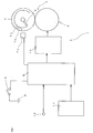
- FIG. 1 shows a basic configuration of the invention and explains it with a vehicle speed meter as an example.
- a pointer instrument 1 of the invention includes a stepping motor 2, a pointer 4 driven by the stepping motor 2 via a speed-reduction mechanism 3, a display board 5 having an index section 5a to be pointed by the pointer 4, control means 6 that drives and controls the stepping motor 2, a detection section 7a that detects a reference position of the pointer 4, a detection object 7b to be detected by the detection section 7a, and a power supply 9 that supplies power to the control means 6 via a power switch 8.
- 10 shows output means, which performs appropriate waveform process of a signal from the control means 6, and supplies the processed signal to the stepping motor 2.
- the number 11 shows ROM (memory storage means).
- the number 12 shows an input terminal, which is connected with a vehicle speed sensor (not shown) in the embodiment.
- a frequency signal from the vehicle speed sensor which is in proportion to travel speed of a vehicle as the measured quantity, is inputted from the input terminal 12 to the control means 6.
- the stepping motor 2 has a stator (not shown) having two coils, and a magnet rotor (not shown).
- the said magnet rotor has a large number of N poles and S poles being alternately magnetized on an outer circumferential face thereof. Rotation of the said magnet rotor is transmitted to the speed-reduction mechanism 3, and the pointer 4 is rotated along with rotation of the speed-reduction mechanism 3.
- the speed-reduction mechanism 3 is configured by a plurality of gears in the embodiment. In the figures, only two gears are shown, including a gear 3S that outputs rotation of the magnet rotor at a stepping motor 2 side, and a gear 3P which the pointer 4 is fixed to.
- the pointer 4 is fixed to the gear 3P configuring the speed-reduction mechanism 3, and driven by rotation of the stepping motor 2 (the magnet rotor) via the speed-reduction mechanism 3.
- the gear 3P fixed with the pointer 4 is hard to rotate due to resistance of a guide member (not shown) or the like unless it is driven by the stepping motor 2.
- the display board 5 has an index section 5a which is pointed by the pointer 4, and the index section 5a includes at least a scale, and letters corresponding to the scale. Furthermore, numbers on the scale are printed in a way that the number increases as it advances clockwise.
- the control means 6 includes a microcomputer that receives a frequency signal corresponding to the measured quantity from the input terminal 12, and outputs the signal corresponding to the measure quantity to the stepping motor 2 to drive the stepping motor.
- the detection section 7a detects the detection object 7b in a non-contact manner, and an optical sensor is used for the detection section in the embodiment.
- the detection object 7b is to be detected by the detection section 7a, and provided on the gear 3P fixed to the pointer 4.
- a positional relationship between the pointer 4 and the detection object 7b is determined so as to form a predetermined angle between them, so that they are configured such that when the detection object 7b (a boundary between the gear 3P and the detection object 7b) is detected, which position on the display board 5 is indicated by the pointer 4 can be determined.
- the detection section and detection object have distinct colors so that the optical sensor which is used for this embodiment is able to differentiate them and detect the detection object 7b.
- the detection object 7b is formed with a black printed layer. When gear 3P has a blackish color, the detection object 7b has a whitish color.
- the detection section 7a and the detection object 7b collectively configure pointer reference-position setting means that can determine a reference position of the pointer 4 in processing as described later.
- the pointer reference-position setting means 7a and 7b are the detection section 7a consists of the optical sensor and the detection object 7b consists of the printed layer.
- the embodiment is not limitative to it.
- magnetic detection means may be used for the detection section 7a, and a magnet or a magnetic material may be used for the detection object 7b.
- the pointer reference-position setting means may be configured by the pointer 4 and a pointer stopper for stopping rotation of the pointer 4.
- the power switch 8 and the power supply 9 correspond to an ignition key switch 8 and in-vehicle battery 9 respectively.
- the power is supplied from the in-vehicle battery 9 to the control means 6 through the ignition key switch 8.
- the control means 6 is configured such that it detects supply of the power though the ignition key switch 8, and performs zero initialization (zero detection process) of the stepping motor 2.
- the ROM 11 is a rewritable storage means such as EEPROM.
- the ROM stores the data of displacement between the 0 scale on the display board 5 and a position indicated by the pointer 4 when the detection section 7a detects the detection object 7b.
- the ROM stores data of an output angle is passing through a control initial, the data corresponding to data of a measurement signal of input vehicle speed.
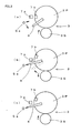
- Fig. 2 shows drive process of the pointer 4
- Figs. 3 and 4 show motions of the stepping motor 2 and the pointer 4 respectively.
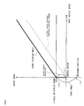
- Fig. 5 shows a relationship between the input vehicle speed and the output angle of the gear 3S of the stepping motor 2.
- the power is supplied to the control means 6 through operation of the ignition key switch 8 being the power switch 8.
- the control means 6 detects such supply of power, and starts the pointer drive process.
- step S1 the control means 6 receives measurement a measured signal of the input vehicle speed, and calculates an output angle based on the output angle data from the control origin, the data being corresponding to the input vehicle speed stored in the ROM 11.
- step S2 if the data of the measured signal is zero which means the vehicle speed is zero, a backlash return flag is made to be 1. If the data of the measured signal is larger than zero, the backlash return flag is made to be 0.
- step S3 whether "0" scale pointing process, which is for pointing the "0" scale on the index section 5a of the display board 5 by the pointer 4, is completed is determined.
- the process is advanced to step S4, and when it is not completed, the process is advanced to step S8. Since the zero detection process of the stepping motor 2 is typically not completed immediately after the power is supplied through operation of the power switch 8, determination is made as "NO", and the process is advanced to the step S8.
- step S8 the process of the step S8 is first described.
- step S8 the "0" scale pointing process is carried out.
- the motion of the stepping motor 2 and the pointer 4 are described using Figs. 3 and 4
- a relationship between the input vehicle speed and an output angle of the gear 3S of the stepping motor 2 is described using Fig. 5 .
- control means 6 Immediately after the power is supplied, the control means 6 does not recognize which portion on the display board 5 is pointed by the pointer 4. Therefore, in order to recognize the position of the pointer 4, the control means 6 rotates the pointer 4 in a direction to the initial position.
- the rotation direction is unidirectional and the pointer 4 rotates counterclockwise in the embodiment.
- the control means 6 drives the stepping motor 2 so that the gear 3S rotates clockwise described in Fig. 3(a) .
- the rotation of the gear 3S causes the gear 3P that is fixed to the pointer 4 to rotate counterclockwise.
- the detection object7b provided on the gear 3P rotates along with the rotation of the gear 3P.
- the detection section 7a configuring the pointer reference-position setting means detects the detection object 7b provided on the gear 3P
- the detection section 7a outputs a pointer reference-position arrival signal to the control means 6, and the control means 6 recognizes a reference position of the pointer 4 with the input of the arrival signal.
- the control means 6 stops rotation of the pointer 4.
- the control means 6 performs the above first drive process.
- the control means 6 performs the second drive process where the pointer 4 is moved by the initial angle in a direction (clockwise direction) opposite to a reset-to-zero direction from the reference position so that the pointer 4 points "0" (zero pointing scale) on the index section 5a of the display board 5 (refer to Fig. 3b ).
- This is the end of the "0" scale pointing process of the step S8.
- a position of the gear 3S of the stepping motor 2 corresponds to a position (b) in Fig. 5 , which is not on the output angle passing through the control origin, and is on an angle given by adding an angle corresponding to a backlash to the output angle passing through the control origin.
- control mean 6 determines whether the "0" scale pointing process of the stepping motor 2 is completed. If the "0" scale pointing process is completed, the control mean 6 is carried out to step S4.
- the control mean 6 determine whether the backlash return flag is 1 or 0. That is, when the data of a measurement signal of vehicle speed is 0, since the backlash return flag is 1, the process is advanced to step S7, and when the data of a measurement signal of the vehicle speed is larger greater than 0, since the backlash return flag is 0, the process is advanced to step S5. In most cases, the vehicle speed is typically 0 immediately after power is supplied. Therefore, processing is advanced to the step S7 for convenience of description.
- step S7 the process is performed as follows.
- a position of the gear 3S of the stepping motor 2 corresponds to a position ((b) in Fig. 5 ), which is on an angle given by adding the angle corresponding to the backlash to the output angle data, passing through the control origin, corresponding to the measurement signal data. Therefore, the gear 3S of the stepping motor 2 is made to have a target output angle obtained by performing backlash return so that the position of the gear 3S corresponds to a position ((c) in Fig. 5 ) on the output angle data, passing through the control origin, corresponding to the measurement signal data.
- step S6 the control means 6 performs a generation process of a target pointing angle for pointing the index section 5a on the display board 5 based on the output pointing angle data corresponding to the measurement signal data, and outputs a signal of the target pointing angle to an output circuit to drive the stepping motor 2.
- the motion of the stepping motor 2 and the pointer 4 during performing such backlash return are described using Figs. 3 and 4 .
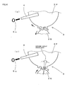
- Figs. 3 and 4 are in such a relation that Fig. 4(b) is an expanded view of Fig. 3(b)
- Fig. 4(c) is an expanded view of Fig. 3(c) .
- the backlash return corresponds to the third drive process of the invention, in which only the gear 3S at the stepping motor 2 side of the speed-reduction mechanism 3 is moved by the second angle. In this case, a position of the gear 3S is shifted from (b) to (c) in Fig. 5 .
- the second angle is corresponding to a backlash existing between a plurality of gears configuring the speed-reduction mechanism 3, and corresponds to the backlash between the gear 3S and the gear 3P in the embodiment.
- the pointer 4 Due to rotation of the gear 3S at the stepping motor 2 side, the pointer 4 is rotatable clockwise in a state of Fig. 4 (b) , but the pointer 4 is rotatable counterclockwise in a state of Fig. 4(c) .
- the pointer 4 of the invention is made such that the gear 3P fixed with the pointer 4 is hardly rotated due to resistance of a guide member or the like unless it is driven by the stepping motor 2.
- step S4 when a backlash return flag is determined to be 0, that is, when vehicle speed is not 0, the process is advanced to step S5.
- step S5 the output angle data, passing through the control origin, corresponding to the measurement signal data is added with an angle corresponding to the backlash. Then, processing is advanced to step S6, in which the control means 6 performs generation processing of a target pointing angle for pointing the index section 5a on the display board 5, and outputs a signal of the target pointing angle to the output circuit to drive the stepping motor 2.
- control means 6 performs processing of returning the gear 3S of the stepping motor 2 by the second angle, that is, by the angle corresponding to the backlash so that the gear 3S has the output angle passing through the control origin by performing the process of the step S7 in order to forcibly position the pointer 4 at the "0" scale position on the index section 5a of the display board 5.
- the reference position of the pointer 4 is set when the stepping motor 2 is powered on.
- the embodiment is not limitative, and the reference position of the pointer 4 may be set when the stepping motor 2 is powered off.
- the invention is preferable for a pointer instrument that uses a stepping motor to measure and indicate measured quantity such as travel speed or engine speed for a vehicle based on frequency signal input in proportion to the measured quantity.
Landscapes
- Engineering & Computer Science (AREA)
- Power Engineering (AREA)
- Physics & Mathematics (AREA)
- General Physics & Mathematics (AREA)
- Control Of Stepping Motors (AREA)
- Instrument Panels (AREA)
- Indicating Measured Values (AREA)
Claims (3)
- Zeigerinstrument (1), das Folgendes umfasst:einen Schrittmotor (2);einen Zeiger (4), der durch Drehungen des Schrittmotors (2) über einen Untersetzungsmechanismus (3) mit mehreren Zahnrädern (3P, 3S) angetrieben wird;eine Anzeigetafel (5) mit einem Indexabschnitt (5a), damit der Zeiger (4) darauf zeigt;ein Steuermittel (6), das konfiguriert ist zum Ansteuern und Steuern des Schrittmotors (2); undein Zeigerreferenzpositionseinstellmittel (7a, 7b), das konfiguriert ist zum Bestimmen einer Referenzposition des Zeigers (4);wobei das Steuermittel (6) konfiguriert ist zum Durchführen, wenn der Schrittmotor (2) ein- oder ausgeschaltet wird:eines ersten Ansteuerprozesses, bei dem der Zeiger (4) in einer Richtung der Referenzposition gedreht wird und bei dem die Drehung des Zeigers (4) als Reaktion auf eine Eingabe eines Zeigereferenzpositionsankunftssignals von dem Zeigerreferenzpositionseinstellmittel (7a, 7b) gestoppt wird;einen zweiten Ansteuerprozess, bei dem der Zeiger (4) von der Referenzposition um einen ersten Winkel in einer der Referenzpositionsrichtung entgegengesetzen Richtung bewegt wird und bei dem eine Position, bei der der Zeiger (4) gestoppt wird, auf eine Nullzeigeskala auf der Anzeigetafel (5a) eingestellt wird; undeinen dritten Ansteuerprozess, bei dem ein Zahnrad (3S) auf einer Seite des Schrittmotors (2) des Untersetzungsmechanismus (3) um einen Winkel bewegt wird, der einem Spiel entspricht, das zwischen den mehreren Zahnrädern (3S, 3P) des Untersetzungsmechanismus (3) besteht.
- Zeigerinstrument (1) nach Anspruch 1, wobei
die Zeigerreferenzpositionseinstellmittel (7a, 7b) ein Detektionsobjekt (7b) zum Spezifizieren einer Position des Zeigers (4) und eine Detektionssektion (7a), die konfiguriert ist zum Detektieren des Detektionsobjekts (7b) auf kontaktfreie Weise, enthalten. - Zeigerinstrument (1) nach Anspruch 1, wobei
das Steuermittel (6) mit der Fahrzeuggeschwindigkeit eingegeben wird und wobei das Steuermittel (6) konfiguriert ist zum erzwungenen Positionieren des Zeigers (4) auf eine Position der Nullzeigeskala, wenn die Fahrzeuggeschwindigkeit Null beträgt.
Applications Claiming Priority (2)
| Application Number | Priority Date | Filing Date | Title |
|---|---|---|---|
| JP2006178921A JP4962702B2 (ja) | 2006-06-29 | 2006-06-29 | 指針式計器 |
| PCT/JP2007/062279 WO2008001642A1 (fr) | 2006-06-29 | 2007-06-19 | Instrument de mesure à aiguille |
Publications (3)
| Publication Number | Publication Date |
|---|---|
| EP2042842A1 EP2042842A1 (de) | 2009-04-01 |
| EP2042842A4 EP2042842A4 (de) | 2010-10-20 |
| EP2042842B1 true EP2042842B1 (de) | 2015-05-06 |
Family
ID=38845410
Family Applications (1)
| Application Number | Title | Priority Date | Filing Date |
|---|---|---|---|
| EP20070745499 Ceased EP2042842B1 (de) | 2006-06-29 | 2007-06-19 | Zeiger-messinstrument |
Country Status (6)
| Country | Link |
|---|---|
| US (1) | US8056388B2 (de) |
| EP (1) | EP2042842B1 (de) |
| JP (1) | JP4962702B2 (de) |
| KR (1) | KR101359881B1 (de) |
| CN (1) | CN101479573B (de) |
| WO (1) | WO2008001642A1 (de) |
Families Citing this family (11)
| Publication number | Priority date | Publication date | Assignee | Title |
|---|---|---|---|---|
| KR100982236B1 (ko) * | 2008-07-07 | 2010-09-14 | 엘아이지넥스원 주식회사 | 백래쉬 측정 장치 및 방법 |
| KR101495078B1 (ko) * | 2008-08-01 | 2015-02-24 | 삼성전자주식회사 | 지침 표시 장치 |
| JP4760926B2 (ja) * | 2009-02-05 | 2011-08-31 | 株式会社デンソー | 車両用指示計器 |
| DE102009056259B4 (de) | 2009-11-28 | 2019-05-16 | Festo Ag & Co. Kg | Messanordnung |
| KR101169249B1 (ko) * | 2011-03-10 | 2012-08-06 | 나사렛대학교 산학협력단 | 장애인용 보완대체 의사소통 장치 |
| GB2512350B (en) * | 2013-03-27 | 2015-08-19 | Visteon Global Tech Inc | Dual pointer display |
| JP6205220B2 (ja) * | 2013-09-13 | 2017-09-27 | 矢崎総業株式会社 | 指針式メータ装置 |
| JP6205219B2 (ja) * | 2013-09-13 | 2017-09-27 | 矢崎総業株式会社 | 指針式メータ装置 |
| JP6406050B2 (ja) * | 2015-02-19 | 2018-10-17 | 株式会社デンソー | ヘッドアップディスプレイ装置 |
| KR102577252B1 (ko) * | 2016-10-27 | 2023-09-11 | 현대모비스 주식회사 | 차량용 지시계의 원점 검출 방법 |
| US11530936B2 (en) * | 2019-08-01 | 2022-12-20 | Denso International America, Inc. | Plug-and-play stepper motor for a pointer display assembly |
Family Cites Families (10)
| Publication number | Priority date | Publication date | Assignee | Title |
|---|---|---|---|---|
| US3484666A (en) * | 1966-06-20 | 1969-12-16 | Warner Electric Brake & Clutch | Servo system |
| JP2979612B2 (ja) | 1990-09-14 | 1999-11-15 | 松下電器産業株式会社 | 電子部品実装機 |
| JPH087518Y2 (ja) * | 1991-04-23 | 1996-03-04 | デンケンエンジニアリング株式会社 | 指針指示値の検出装置 |
| JPH06129877A (ja) * | 1992-09-04 | 1994-05-13 | Yazaki Corp | デジタル・アナログ表示装置 |
| CN2408438Y (zh) * | 2000-02-16 | 2000-11-29 | 杨友修 | 微型步进电机驱动的指针式指示器 |
| JP4404442B2 (ja) | 2000-04-28 | 2010-01-27 | 矢崎総業株式会社 | 駆動装置及び、駆動制御装置 |
| JP4176984B2 (ja) * | 2001-10-23 | 2008-11-05 | 矢崎総業株式会社 | ステッピングモータ用駆動装置及び指針打込方法 |
| JP3828792B2 (ja) * | 2001-11-30 | 2006-10-04 | 矢崎総業株式会社 | ステッピングモータ用移動量算出装置及びステッピングモータ用駆動装置 |
| JP4541071B2 (ja) * | 2004-08-25 | 2010-09-08 | カルソニックカンセイ株式会社 | 指示計器および初期化駆動装置 |
| JP4123498B2 (ja) | 2005-07-14 | 2008-07-23 | 財団法人富山県新世紀産業機構 | Dnaの検出方法 |
-
2006
- 2006-06-29 JP JP2006178921A patent/JP4962702B2/ja not_active Expired - Fee Related
-
2007
- 2007-06-19 WO PCT/JP2007/062279 patent/WO2008001642A1/ja not_active Ceased
- 2007-06-19 CN CN200780024600XA patent/CN101479573B/zh not_active Expired - Fee Related
- 2007-06-19 EP EP20070745499 patent/EP2042842B1/de not_active Ceased
- 2007-06-19 US US12/306,845 patent/US8056388B2/en not_active Expired - Fee Related
- 2007-06-19 KR KR1020097000380A patent/KR101359881B1/ko not_active Expired - Fee Related
Also Published As
| Publication number | Publication date |
|---|---|
| JP4962702B2 (ja) | 2012-06-27 |
| KR101359881B1 (ko) | 2014-02-06 |
| WO2008001642A1 (fr) | 2008-01-03 |
| EP2042842A4 (de) | 2010-10-20 |
| US8056388B2 (en) | 2011-11-15 |
| CN101479573B (zh) | 2012-01-04 |
| CN101479573A (zh) | 2009-07-08 |
| EP2042842A1 (de) | 2009-04-01 |
| JP2008008728A (ja) | 2008-01-17 |
| KR20090024785A (ko) | 2009-03-09 |
| US20090277373A1 (en) | 2009-11-12 |
Similar Documents
| Publication | Publication Date | Title |
|---|---|---|
| US8056388B2 (en) | Pointer instrument | |
| KR100499729B1 (ko) | 차량용 지시계기 | |
| US8836262B2 (en) | Method and arrangement for determining the dynamic state of an electric motor | |
| US6956351B2 (en) | Driving device for stepping motor | |
| US8237394B2 (en) | Method for initializing indicating instrument for vehicle | |
| EP2180295A1 (de) | Inkrementale Positions-, Geschwindigkeits- und Richtungserkennungsvorrichtung und Verfahren für drehende Objekte unter Nutzung eines magnetischen Widerstandsensors | |
| JP4387750B2 (ja) | 指示位置補正方法及びその装置、並びに、指示装置 | |
| CN103210196A (zh) | 用于对内燃机进行转速检测的控制装置和方法 | |
| EP2071718B1 (de) | Schrittmotor-antriebssteuereinrichtung und antriebssteuerverfahren | |
| US20160178413A1 (en) | Indicating-needle type meter device | |
| JP5447319B2 (ja) | 車両用指示計器 | |
| JPH0662322U (ja) | アブソリュートエンコーダ装置 | |
| US7439701B2 (en) | Method and device for detecting initial excitation phase of stepping motor | |
| JP5528902B2 (ja) | ステッピングモータ装置 | |
| JP2000018975A (ja) | ステッピングモータ式計器装置 | |
| JP4825588B2 (ja) | ステッパモータ装置及びステッパモータの制御方法 | |
| JP2002084791A (ja) | ステッパモータ駆動回路 | |
| JP5847499B2 (ja) | ステッピングモータ装置 | |
| JP4695900B2 (ja) | 計器装置 | |
| JP4681955B2 (ja) | ステッパモータの初期励磁相検出方法及びその装置 | |
| JP5459350B2 (ja) | 車両用指示計器 | |
| JP5244222B2 (ja) | 指針型表示器のモータ制御装置 | |
| KR20000055856A (ko) | 차량용 영구 자석형 동기 모터의 회전자 위치 검출 방법 | |
| JP2001341553A (ja) | 指示計器の駆動方法 |
Legal Events
| Date | Code | Title | Description |
|---|---|---|---|
| PUAI | Public reference made under article 153(3) epc to a published international application that has entered the european phase |
Free format text: ORIGINAL CODE: 0009012 |
|
| 17P | Request for examination filed |
Effective date: 20090112 |
|
| AK | Designated contracting states |
Kind code of ref document: A1 Designated state(s): AT BE BG CH CY CZ DE DK EE ES FI FR GB GR HU IE IS IT LI LT LU LV MC MT NL PL PT RO SE SI SK TR |
|
| AX | Request for extension of the european patent |
Extension state: AL BA HR MK RS |
|
| RIN1 | Information on inventor provided before grant (corrected) |
Inventor name: SASAKI, KATSUHIRONIPPON SEIKI CO.,LTD Inventor name: KOBAYASHI, SATOSHINIPPON SEIKI CO.,LTD |
|
| DAX | Request for extension of the european patent (deleted) | ||
| RBV | Designated contracting states (corrected) |
Designated state(s): DE FR GB IT |
|
| A4 | Supplementary search report drawn up and despatched |
Effective date: 20100916 |
|
| GRAP | Despatch of communication of intention to grant a patent |
Free format text: ORIGINAL CODE: EPIDOSNIGR1 |
|
| INTG | Intention to grant announced |
Effective date: 20150121 |
|
| RIN1 | Information on inventor provided before grant (corrected) |
Inventor name: KOBAYASHI, SATOSHI Inventor name: SASAKI, KATSUHIRO |
|
| GRAS | Grant fee paid |
Free format text: ORIGINAL CODE: EPIDOSNIGR3 |
|
| GRAA | (expected) grant |
Free format text: ORIGINAL CODE: 0009210 |
|
| AK | Designated contracting states |
Kind code of ref document: B1 Designated state(s): DE FR GB IT |
|
| REG | Reference to a national code |
Ref country code: GB Ref legal event code: FG4D |
|
| REG | Reference to a national code |
Ref country code: DE Ref legal event code: R096 Ref document number: 602007041360 Country of ref document: DE Effective date: 20150618 |
|
| PG25 | Lapsed in a contracting state [announced via postgrant information from national office to epo] |
Ref country code: IT Free format text: LAPSE BECAUSE OF FAILURE TO SUBMIT A TRANSLATION OF THE DESCRIPTION OR TO PAY THE FEE WITHIN THE PRESCRIBED TIME-LIMIT Effective date: 20150506 |
|
| REG | Reference to a national code |
Ref country code: DE Ref legal event code: R097 Ref document number: 602007041360 Country of ref document: DE |
|
| PLBE | No opposition filed within time limit |
Free format text: ORIGINAL CODE: 0009261 |
|
| STAA | Information on the status of an ep patent application or granted ep patent |
Free format text: STATUS: NO OPPOSITION FILED WITHIN TIME LIMIT |
|
| 26N | No opposition filed |
Effective date: 20160209 |
|
| REG | Reference to a national code |
Ref country code: FR Ref legal event code: PLFP Year of fee payment: 10 |
|
| REG | Reference to a national code |
Ref country code: FR Ref legal event code: PLFP Year of fee payment: 11 |
|
| REG | Reference to a national code |
Ref country code: FR Ref legal event code: PLFP Year of fee payment: 12 |
|
| PGFP | Annual fee paid to national office [announced via postgrant information from national office to epo] |
Ref country code: DE Payment date: 20180605 Year of fee payment: 12 |
|
| PGFP | Annual fee paid to national office [announced via postgrant information from national office to epo] |
Ref country code: FR Payment date: 20180511 Year of fee payment: 12 |
|
| PGFP | Annual fee paid to national office [announced via postgrant information from national office to epo] |
Ref country code: GB Payment date: 20180613 Year of fee payment: 12 |
|
| REG | Reference to a national code |
Ref country code: DE Ref legal event code: R119 Ref document number: 602007041360 Country of ref document: DE |
|
| GBPC | Gb: european patent ceased through non-payment of renewal fee |
Effective date: 20190619 |
|
| PG25 | Lapsed in a contracting state [announced via postgrant information from national office to epo] |
Ref country code: GB Free format text: LAPSE BECAUSE OF NON-PAYMENT OF DUE FEES Effective date: 20190619 Ref country code: DE Free format text: LAPSE BECAUSE OF NON-PAYMENT OF DUE FEES Effective date: 20200101 |
|
| PG25 | Lapsed in a contracting state [announced via postgrant information from national office to epo] |
Ref country code: FR Free format text: LAPSE BECAUSE OF NON-PAYMENT OF DUE FEES Effective date: 20190630 |