EP2042852A1 - Verfahren und vorrichtung zur bewertung der stärke einer dielektrophorese von feinpartikeln - Google Patents
Verfahren und vorrichtung zur bewertung der stärke einer dielektrophorese von feinpartikeln Download PDFInfo
- Publication number
- EP2042852A1 EP2042852A1 EP06781228A EP06781228A EP2042852A1 EP 2042852 A1 EP2042852 A1 EP 2042852A1 EP 06781228 A EP06781228 A EP 06781228A EP 06781228 A EP06781228 A EP 06781228A EP 2042852 A1 EP2042852 A1 EP 2042852A1
- Authority
- EP
- European Patent Office
- Prior art keywords
- particles
- dielectrophoretic
- diffraction grating
- intensity
- medium
- Prior art date
- Legal status (The legal status is an assumption and is not a legal conclusion. Google has not performed a legal analysis and makes no representation as to the accuracy of the status listed.)
- Granted
Links
Images


Classifications
-
- G—PHYSICS
- G01—MEASURING; TESTING
- G01N—INVESTIGATING OR ANALYSING MATERIALS BY DETERMINING THEIR CHEMICAL OR PHYSICAL PROPERTIES
- G01N21/00—Investigating or analysing materials by the use of optical means, i.e. using sub-millimetre waves, infrared, visible or ultraviolet light
- G01N21/17—Systems in which incident light is modified in accordance with the properties of the material investigated
- G01N21/47—Scattering, i.e. diffuse reflection
- G01N21/4788—Diffraction
-
- B—PERFORMING OPERATIONS; TRANSPORTING
- B03—SEPARATION OF SOLID MATERIALS USING LIQUIDS OR USING PNEUMATIC TABLES OR JIGS; MAGNETIC OR ELECTROSTATIC SEPARATION OF SOLID MATERIALS FROM SOLID MATERIALS OR FLUIDS; SEPARATION BY HIGH-VOLTAGE ELECTRIC FIELDS
- B03C—MAGNETIC OR ELECTROSTATIC SEPARATION OF SOLID MATERIALS FROM SOLID MATERIALS OR FLUIDS; SEPARATION BY HIGH-VOLTAGE ELECTRIC FIELDS
- B03C5/00—Separating dispersed particles from liquids by electrostatic effect
- B03C5/005—Dielectrophoresis, i.e. dielectric particles migrating towards the region of highest field strength
-
- B—PERFORMING OPERATIONS; TRANSPORTING
- B03—SEPARATION OF SOLID MATERIALS USING LIQUIDS OR USING PNEUMATIC TABLES OR JIGS; MAGNETIC OR ELECTROSTATIC SEPARATION OF SOLID MATERIALS FROM SOLID MATERIALS OR FLUIDS; SEPARATION BY HIGH-VOLTAGE ELECTRIC FIELDS
- B03C—MAGNETIC OR ELECTROSTATIC SEPARATION OF SOLID MATERIALS FROM SOLID MATERIALS OR FLUIDS; SEPARATION BY HIGH-VOLTAGE ELECTRIC FIELDS
- B03C5/00—Separating dispersed particles from liquids by electrostatic effect
- B03C5/02—Separators
- B03C5/022—Non-uniform field separators
- B03C5/026—Non-uniform field separators using open-gradient differential dielectric separation, i.e. using electrodes of special shapes for non-uniform field creation, e.g. Fluid Integrated Circuit [FIC]
-
- G—PHYSICS
- G01—MEASURING; TESTING
- G01N—INVESTIGATING OR ANALYSING MATERIALS BY DETERMINING THEIR CHEMICAL OR PHYSICAL PROPERTIES
- G01N15/00—Investigating characteristics of particles; Investigating permeability, pore-volume or surface-area of porous materials
- G01N2015/0003—Determining electric mobility, velocity profile, average speed or velocity of a plurality of particles
-
- G—PHYSICS
- G01—MEASURING; TESTING
- G01N—INVESTIGATING OR ANALYSING MATERIALS BY DETERMINING THEIR CHEMICAL OR PHYSICAL PROPERTIES
- G01N15/00—Investigating characteristics of particles; Investigating permeability, pore-volume or surface-area of porous materials
- G01N2015/0038—Investigating nanoparticles
Definitions
- the present invention relates to a dielectrophoretic intensity evaluation method and apparatus for microparticles including so-called nanoparticles of 100 nm or less in particle size.
- Particles of 100 nm or less in size are generally called nanoparticles, and are just beginning to be used in various fields since they show properties different from those of a general bulk matter composed of the same material. In such a situation, it is becoming important to evaluate the properties of the microparticles.
- Dielectrophoresis is known as an evaluation method for microparticle. Dielectrophoresis phenomenon is a phenomenon in which electric polarization is occurred in particles, even if they are charge-free, by applying a strong nonuniform electric field, and the particles are moved due to the attractive force unbalance for polarized positive and negative charges altered by the nonuniform electric field.
- the intensity of dielectrophoresis is involved by important properties related to physical properties of a particle, such as respective complex dielectric constants of the particle and a medium thereof, and diffusion coefficient. Therefore, by evaluating dielectrophoretic sensitivity of the particle, evaluations for physical properties of the particle and the dispersion medium and for the interaction between the both can be performed.
- a typical method for observing the dielectrophoretic intensity of microparticle is direct observation of migrating particles by a microscope.
- the microscopic observation cannot be applied to nanoparticle with a particle size below an optical microscopic observable limit. Therefore, it is proposed to chemically bond a phosphor to the nanoparticle, so that intensity distribution of fluorescent emission can be observed even for a particle smaller than optical resolution.
- the conventional particle evaluation method by dielectrophoresis using video observation of fluorescent particles as described above has the following three disadvantages.
- a dielectrophoretic intensity evaluation method comprises the steps of forming a distribution of AC electric field regularly arranged in a cell while storing a sample having particles dispersed in a medium in the cell, thereby dielectrically migrating the particles in the medium to generate a diffraction grating by density distribution of the particles; detecting diffracted light generated by irradiating the diffraction grating by density distribution with measuring light; and performing characteristic evaluation of the particles and/or the medium from the detection result (first aspect).
- frequency dependency of dielectrophoretic intensity or dielectrophoretic sensitivity of a sample can be also evaluated based on a difference in detection result of each diffracted light by performing an operation of forming the distribution of AC electric field in a cell while storing the sample having particles dispersed in a medium within the cell, thereby dielectrically migrating the particles in the medium to generate a diffraction grating by the particles, and detecting diffracted light generated by irradiating the diffraction grating with measuring light, the operation being performed to the same sample more than once by varying frequency of the AC electric field (second aspect).
- field intensity dependency of dielectrophoretic intensity or dielectrophoretic sensitivity of a sample can be evaluated based on a difference in detection result of each diffracted light by performing an operation of forming the distribution of AC electric field in a cell while storing the sample having particles dispersed in a medium within the cell, thereby dielectrically migrating the particles in the medium to generate a diffraction grating by the particles, and detecting diffracted light generated by irradiating the diffraction grating with measuring light, the operation being performed to the same sample more than once by varying intensity of the AC electric field (third aspect).
- the dielectrophoretic intensity depends not only on dielectric constants of the microparticle and the medium but also on the cube of particle size of the microparticle, only dielectric constant information of the microparticle and the medium can be separately extracted by correcting the particle size information based on dielectrophoretic intensity data obtained by acquiring the particle size of the microparticle as described later.
- information for dielectrophoretic intensity in a sample composed of a combination of a medium and particles dispersed therein can be taken out as signal by dielectrically migrating the particles dispersed in the medium within a cell by formation of regular or spatially periodic AC electric field in the cell to generate a diffraction grating by density distribution of the particles, and measuring diffracted light by the diffraction grating, and the intensity of dielectrophoresis can consequently be quantitatively evaluated without needing a pretreatment such as adhesion of a phosphor to the particles.
- a density distribution, of the particles is caused corresponding to the spatial pattern of the AC electric field as a result of migration of the particles according to the spatial pattern of the electric field, whereby the diffraction grating by density distribution of the particles is generated. Since the intensity of the diffracted light generated by irradiating the diffraction grating with measuring light depends on the magnitude of modulation (contrast) of the diffraction grating by density distribution of the particles, the momentary generation state of diffraction grating can be acquired from the temporal information of the diffracted light.
- the migrating force of the particles in the medium can be evaluated from the manner of increasing of the diffracted light. Further, since particle size information can be obtained from the attenuation rate of the diffracted light after stopping dielectrophoresis through a diffusion coefficient, particle size correction data for dielectrophoretic intensity can be acquired also by the single measurement.
- the degree of spatial modulation of the particles can be measured with satisfactory sensitivity only by simply measuring the intensity of the diffracted light of the first order, since the intensity of a specific order (usually, first order) of the diffracted light, from the diffraction grating by density distribution is proportional to the square of the periodic spatial modulation degree of the particles.
- dielectrophoretic characteristics can be measured even for microparticles of several nanometers in diameter which are naturally low in dielectrophoretic effect due to the advantages of no need of phosphor, enhanced quantitative determination property, and further improved sensitivity, compared with the conventional evaluation method of dielectrophoresis.
- difference in dielectrophoretic force or the like between samples can be quantitatively evaluated by performing the above-mentioned measurement to different samples in the same electric field condition.
- Difference in dielectrophoretic force or the like to a medium between different kinds of particles can be also quantitatively evaluated by similarly performing the above-mentioned measurement to plural samples, each of them having different kinds of particles dispersed in a common medium in the same electric field condition.
- the contribution of different mediums to dielectrophoresis of a kind of particles can be evaluated by performing the above-mentioned measurement to plural samples, each of them having common particles dispersed in a different medium in the same electric field condition.
- the frequency dependency of dielectrophoretic intensity or dielectrophoretic sensitivity of a sample can be evaluated from each measurement result by performing the measurement to the same sample with the frequency of the AC electric field being varied as the second aspect of the present invention.
- the field intensity dependency of dielectrophoretic intensity or dielectrophoretic sensitivity of a sample can be evaluated from each measurement result by performing the measurement to the same sample with the intensity of the AC electric field being varied as the third aspect of the present invention.
- particle size information determined from the attenuation rate of diffraction grating after stopping dielectrophoresis can be used, as the fourth aspect of the invention, to correct the term of the cube of particle size contained in the equation of dielectrophoretic intensity.
- the dielectrophoretic intensity evaluation apparatus is an apparatus for executing the above-mentioned method of the present invention, which comprises a cell for holding a sample having particles dispersed in a medium; an AC power source; a pair of electrodes for forming an electric field distribution regularly arranged within the cell by applying voltage from the AC power source; a light source for irradiating a diffraction grating resulting from a density distribution caused by dielectrophoresis of the particles by formation of the electric field with measuring light; a light detector for detecting diffracted light of the measuring light by the diffraction grating; and a recording means for recording output of the light detector during the period between starting of voltage application to the electrodes and at least stoppage or modulation of the application.
- the whole body or at least two wall bodies of the cell through which the measuring light passes are formed of a transparent material such as quartz glass.
- the electrodes can be adapted to be formed inside the wall bodies composed of the transparent material of the cell, suitably, with a pattern in which a pair of comb-like electrode each including a plurality of parallel linear electrode pieces connected at one-side end portion is disposed so that each electrode piece of one electrode is fitted to between electrode pieces of the other electrode.
- each comb-like electrode is formed so that an electrode piece eccentrically-located area including at least two linear electrode pieces disposed adjacently to each other, and an electrode piece absent area free from electrodes pieces are alternately located, and a pattern in which each comb-tooth electrode is disposed so that the electrode piece eccentrically-located area of one comb-like electrode is located in the electrode piece absent area of the other comb-like electrode can be more suitably adopted.
- the grating pitch of density distribution-induced diffraction grating of the particles becomes larger than the grating pitch of diffraction grating formed by the electrode pieces, and the outgoing directions of diffracted light can be differed between both the diffraction gratings.
- the diffracted light by density distribution of the particles can be selectively detected to improve S/N of measurement.
- migrating force will be described with view of positive migrating force for capturing particles by attraction, negative migrating force having repelling force also similarly functions as a diffraction grating, with a particle density modulation being formed in the vicinity of the electrodes so that the particle density is lower than in the circumference.
- the apparatus includes, as main components, a cell 1 for storing a sample having particles movably dispersed therein, for example, a sample having particles dispersed in a liquid, or a sample composed of a gel having particles movably dispersed therein; an electrode power source 3 which applies voltage to an electrode pair 2 provided within the cell 1; an irradiation optical system 4 for irradiating light to the cell 1; a detection optical system 5 for measuring diffracted light from a diffraction grating by density distribution of the particles generated within the cell 1 by the application of voltage to the electrode pair 2; and a device control and data retrieving processor 6 which controls the whole apparatus and also retrieves output from the detection optical system 5 through an amplifier 6a to perform data processing thereto.
- a cell 1 for storing a sample having particles movably dispersed therein, for example, a sample having particles dispersed in a liquid, or a sample composed of a gel having particles movably dispersed therein
- an electrode power source 3 which
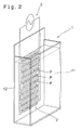
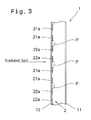
- the cell 1 has at least mutually parallel wall bodies 11 and 12 each composed of a transparent material, as shown in the perspective view of Fig 2 and the schematic enlarged sectional view of Fig. 3 , and the electrode pair 2 is formed on a surface (inner surface) of one wall body 12.
- the electrode pair 2 is composed of electrodes 21 and 22, as shown in Fig. 4 , which are comb-like electrodes each having a plurality of mutually parallel electrode pieces 21a or 22a and a connecting part 21b, 22b which electrically connects the respective electrode pieces 21a or 22a to each other.
- Each electrode 21, 22 has a shape in which an electrode piece eccentrically-located area having two linear electrode pieces 21a or 22a disposed adjacently to each other, and an electrode piece absent area free from electrode pieces are alternately formed. Namely, two of the electrode pieces 21a, 22a of each electrode 21, 22 are alternately located in parallel at regular intervals as the whole, with two electrode pieces 21a or 22a in the electrode piece eccentrically-located area of one electrode being fitted to the electrode piece absent area of the other.
- the irradiation optical system 4 outputs a substantially monochromatic light while shaping it into a substantially parallel light flux, and the output light is irradiated toward the surface with the electrode pair 2 formed thereon of the cell 1.
- a monochromic light such as laser or LED is easy to use.
- a continuous wavelength light source can be used also if the light thereof is made pseudo-monochromic by a band pass filter, a spectrometer or the like, with a spectrum band width of about several tens nm or less, for example, in a visible wavelength band.
- the detection optical system 5 is disposed, for example, in the outgoing direction of the first order light diffracted by the diffraction grating by density distribution of the particles within the cell 1 of the light from the irradiation optical system 4.
- the detection optical system 5 is composed of, for example, a pin hole 5a and a light detector 5b.
- the detection optical system 5 measures a change in diffracted light intensity by the diffraction grating by density distribution of particles in the cell 1 in time series.
- the pin hole and the detector may be disposed in a necessary order position to detect the intensity therein.
- the high density area P of the particles is spatially repeatedly formed at twice the arrangement pitch of the electrode piece 21a or 22a in parallel to the electrode pieces 21a and 22a, and the diffraction grating is formed by a plurality of high density areas P of the particles.
- the light from the irradiation optical system 4 is diffracted, when irradiated to such diffraction grating by density distribution of the particles, by the diffraction grating.
- the diffraction grating by density distribution of particles has grating patch twice as large as that of the diffraction grating formed by the electrode pieces 21a and 22a, so the grating constants are different between both diffraction gratings, and diffracted light of a specific order determined by the grating constant of the diffraction grating formed by the density distribution of the particles appears in a direction where no diffracted light by the diffraction grating formed by the electrodes 21a and 22a is present.
- [2m+1]-order diffracted light (m is an integer) by the diffraction grating formed by the density distribution of particles is formed in directions where no diffracted slight by the diffraction grating formed by the electrode pieces is present. Accordingly, by disposing the detection optical system 5 at one of these directions, background light independent from density diffraction grating can be kept low in the detection light by the detection optical system 5 to minimize fluctuation of background light or shot noise by background light. Consequently, the diffracted light from the diffraction grating by density distribution of the particles can be measured with satisfactory S/N.
- the effect of increasing signals as the square of the number of grooves ensures measurements without being disturbed by the strong diffracted light from the electrode pieces 21a and 22a, and even weak dielectrophoresis can be consequently measured with satisfactory sensitivity.
- Fig. 5 shows a measuring result of diffracted light intensity for a sample having silica particles of 8 nm in diameter dispersed in water as the medium, in which the diffracted light intensity is measured during the period between generation of the diffraction grating by density distribution of particles and disappearance thereof by use of the apparatus of Fig. 1 by varying the frequency of AC voltage applied to the electrode pair 2 to 10 kinds of frequency of 200 KHz to 500 KHz.
- Fig. 5 shows a measuring result of diffracted light intensity for a sample having silica particles of 8 nm in diameter dispersed in water as the medium, in which the diffracted light intensity is measured during the period between generation of the diffraction grating by density distribution of particles and disappearance thereof by use of the apparatus of Fig. 1 by varying the frequency of AC voltage applied to the electrode pair 2 to 10 kinds of frequency of 200 KHz to 500 KHz.
- the time up to 0.2 second is a time zone where the AC voltage is applied, or a time zone where dielectrophoresis is ON, during which the particles periodically collect to form the diffraction grating by density distribution.
- the diffraction grating by density distribution of the particles once formed is exponentially relaxing due to diffusion phenomenon of particles after stopping the application of AC voltage.
- the measurement by varying the frequency is extremely easy to carry out. According to actual measurements, the particles in the medium appear hardly changed even if application/stoppage of AC voltage is repeated, with the reproducibility being relatively retained. Therefore, data as shown in Fig. 5 can be easily collected by repeating the application/stoppage of voltage in a state where the sample including the particles dispersed in the medium is held in the cell 1 while successively varying the frequency.
- the graph of Fig. 6 shows an indicative example of frequency dependency, in which the diffracted light intensity at the point of time 0.1 second in Fig. 5 is plotted with the diffracted light intensity being on the vertical axis and the frequency on the horizontal axis. It is generally known by an optical theory that the electric field formed by diffracted light is proportional to the modulation amplitude of a diffraction grating, and the intensity of the diffracted light is proportional to the square of the electric field. In other words, the square root of diffracted light intensity is proportional to the modulation amplitude of a diffraction grating.
- the square root of the diffracted light intensity of the density grating generated in this embodiment is proportional to the modulation amplitude of the diffraction grating by particles density distribution formed by dielectrophoresis.
- Fig. 6 shows the relation of frequency to diffraction intensity, and if the vertical axis is converted to the square root, the modulation amplitude, which is one of indexes quantitatively showing the effect of dielectrophoresis can be obtained. In this way, information for complex dielectric constant that is a natural electro-optical characteristic of particle can be obtained from the frequency dependency of Fig. 6 as described later.
- the graph of Fig. 7 shows a result of repeated measurements, with varying the amplitude of the AC voltage applied in formation of the diffraction grating by density distribution of particles, from 12V to 20 V of peak-to-peak value on a 2-V-basis, while maintaining the frequency of the applied AC voltage constant (500 Hz).
- a larger absolute value of signal is shown at a higher voltage since the modulation of diffraction grating is of course larger as the voltage is higher, the exponential attenuation part on and after stopping the application of voltage is almost parallel.
- the magnitude of diffraction signal at an appropriate point of time in Fig. 7 is plotted to the voltage in formation of the diffraction grating by particle density distribution, whereby Fig. 8 is obtained.
- the diffraction signal has a characteristic such that it does not occur up to a certain threshold voltage and suddenly rises up at a voltage beyond the threshold.
- the threshold is related to the magnitude relation which describes if the dielectrophoretic potential ⁇ dep represented by the following equation (1) exceeds the thermal energy kT or not.
- the mark * shows that each dielectric constant is a complex number
- ⁇ p and ⁇ m represents dielectric constants of the particle and the medium, respectively
- ⁇ p and ⁇ m represent conductivities of the particle and the medium, respectively
- "j" represents the imaginary unit
- ⁇ represents an angular frequency of high frequency applied.
- the dependency on frequency "f" shown in Fig. 6 relates to K* ( ⁇ ) shown in the equation (1).
- Fig. 8 also involves the equation (1). Since dielectrophoresis is observed only when the dielectrophoretic potential ⁇ dep of the equation (1) exceeds the thermal energy kT, the diffraction grating by particle density distribution is induced thereby. The existence of a threshold of dielectrophoresis is thus explained. From Fig. 8 that shows the threshold and signal rise-up manner, the complex dielectric constants of the particle and the dispersion medium can be explained using the equation (1) relating with the above-mentioned frequency characteristics of Fig. 6 .
- a number of traces as shown in Figs. 5 and 7 can be automatically obtained for one sample in a short time by use of the apparatus shown in Fig. 1 while successively varying the frequency and the applied voltage. Accordingly, further information related to properties of a nanoparticle and a dispersion medium thereof can be acquired by converting and displaying such traces in a diagram of frequency (such as Fig. 6 ) or in a diagram of applied voltage (field intensity, such as Fig. 8 ).
- the K*( ⁇ ) shown in the equation (2) is generally a complex number, and its real part becomes positive or negative depending on the complex dielectric constants ⁇ p * and ⁇ m * of particle and medium.
- the positive and negative of this quantity corresponds to a positive migrating force for capturing particles by attraction and a negative migrating force which appears as repulsive force, and in both cases, the technique of density diffraction grating can be applied.
- the relaxation rate of the diffraction grating after stopping the application of AC voltage to the electrode pair 2 can be also used.
- the diffusion coefficient "D" can be determined from the attenuation coefficient of signal intensity 2(2 ⁇ /A) 2 D on and after time 0.2 second at which the voltage application is stopped to stop dielectrophoresis, and the particle radius "a” can be determined from “D” using the following relation known as the Einstein-Stokes equation.
- the above-mentioned measurement method which utilizes the combination of generation and attenuation of diffraction grating is characterized by that the method enables us to perform extremely efficient evaluation and is particularly useful for a nanoparticle with unknown particle size, because two kinds of information can be obtained at once by acquiring a particle size from the latter attenuation term of Fig. 5 , and determining characteristics of dielectrophoresis from the frequency dependency or field intensity dependency in the generation process of the grating.
- evaluation of dielectrophoresis can be simplified because the procedure is just to measure diffracted light without adhering a phosphor to a particle, and the quantitative determination property of measurement can be enhanced. Further, the sensitivity which was the most serious problem in measurement of dielectrophoresis can be so improved that the new method opens the way to obtaining dielectrophoretic characteristics of microparticles several nm in diameter which generally exhibit very weak dielectrophoretic effect.
- the intensity of dielectrophoresis can be analyzed, including correction with the particle size.
Landscapes
- General Health & Medical Sciences (AREA)
- Life Sciences & Earth Sciences (AREA)
- Chemical & Material Sciences (AREA)
- Health & Medical Sciences (AREA)
- Analytical Chemistry (AREA)
- Electrochemistry (AREA)
- Molecular Biology (AREA)
- Physics & Mathematics (AREA)
- Chemical Kinetics & Catalysis (AREA)
- Biochemistry (AREA)
- General Physics & Mathematics (AREA)
- Immunology (AREA)
- Pathology (AREA)
- Engineering & Computer Science (AREA)
- Microelectronics & Electronic Packaging (AREA)
- Investigating Or Analysing Materials By Optical Means (AREA)
Applications Claiming Priority (1)
| Application Number | Priority Date | Filing Date | Title |
|---|---|---|---|
| PCT/JP2006/314221 WO2008010267A1 (en) | 2006-07-19 | 2006-07-19 | Method and apparatus for evaluating strength of dielectrophoresis of fine particles |
Publications (3)
| Publication Number | Publication Date |
|---|---|
| EP2042852A1 true EP2042852A1 (de) | 2009-04-01 |
| EP2042852A4 EP2042852A4 (de) | 2012-01-04 |
| EP2042852B1 EP2042852B1 (de) | 2017-04-19 |
Family
ID=38956605
Family Applications (1)
| Application Number | Title | Priority Date | Filing Date |
|---|---|---|---|
| EP06781228.9A Ceased EP2042852B1 (de) | 2006-07-19 | 2006-07-19 | Verfahren zur bewertung der stärke einer dielektrophorese von feinpartikeln |
Country Status (4)
| Country | Link |
|---|---|
| US (1) | US8313628B2 (de) |
| EP (1) | EP2042852B1 (de) |
| JP (1) | JP4793601B2 (de) |
| WO (1) | WO2008010267A1 (de) |
Families Citing this family (10)
| Publication number | Priority date | Publication date | Assignee | Title |
|---|---|---|---|---|
| US9283597B2 (en) * | 2002-12-02 | 2016-03-15 | Cfd Research Corporation | Miniaturized electrothermal flow induced infusion pump |
| US20100149532A1 (en) * | 2007-05-18 | 2010-06-17 | Naoji Moriya | Method and apparatus for optical measurement |
| JP4888673B2 (ja) * | 2007-08-08 | 2012-02-29 | 株式会社島津製作所 | 光学的測定装置およびその電極対 |
| JP5109988B2 (ja) * | 2009-01-21 | 2012-12-26 | 株式会社島津製作所 | 粒子径測定装置及び粒子径測定方法 |
| US9261448B2 (en) * | 2014-06-27 | 2016-02-16 | Shimadzu Corporation | Particle size distribution measuring apparatus |
| US10081015B2 (en) * | 2015-07-12 | 2018-09-25 | International Business Machines Corporation | Trapping at least one microparticle |
| US9962714B2 (en) | 2015-07-12 | 2018-05-08 | International Business Machines Corporation | Microchannel, microfluidic chip and method for processing microparticles in a fluid flow |
| KR102102534B1 (ko) * | 2018-07-11 | 2020-04-23 | 주식회사 엑스와이지플랫폼 | 유전 전기 영동을 이용한 마이크로 전극 바이오 센서, 및 이를 이용한 생체물질 검출 방법 |
| JP7599431B2 (ja) * | 2019-11-19 | 2024-12-13 | 株式会社堀場製作所 | 粒子径分布測定装置、及び、粒子径分布測定方法 |
| EP4145110A4 (de) * | 2020-04-28 | 2023-10-04 | Panasonic Intellectual Property Management Co., Ltd. | Zählverfahren und zählvorrichtung |
Family Cites Families (5)
| Publication number | Priority date | Publication date | Assignee | Title |
|---|---|---|---|---|
| US5993630A (en) * | 1996-01-31 | 1999-11-30 | Board Of Regents The University Of Texas System | Method and apparatus for fractionation using conventional dielectrophoresis and field flow fractionation |
| US7760356B2 (en) * | 2004-08-30 | 2010-07-20 | Shimadzu Corporation | Optical measuring device and method, and nanoparticle measuring method and device |
| JP4315083B2 (ja) * | 2004-08-30 | 2009-08-19 | 株式会社島津製作所 | 光学的測定装置および光学的測定方法 |
| JP4270121B2 (ja) * | 2004-12-03 | 2009-05-27 | 株式会社島津製作所 | 光学的測定装置 |
| JP4379318B2 (ja) * | 2004-12-03 | 2009-12-09 | 株式会社島津製作所 | 光学的測定装置および光学的測定方法 |
-
2006
- 2006-07-19 WO PCT/JP2006/314221 patent/WO2008010267A1/ja not_active Ceased
- 2006-07-19 US US12/374,048 patent/US8313628B2/en not_active Expired - Fee Related
- 2006-07-19 EP EP06781228.9A patent/EP2042852B1/de not_active Ceased
- 2006-07-19 JP JP2008525748A patent/JP4793601B2/ja not_active Expired - Fee Related
Also Published As
| Publication number | Publication date |
|---|---|
| JPWO2008010267A1 (ja) | 2009-12-10 |
| JP4793601B2 (ja) | 2011-10-12 |
| EP2042852B1 (de) | 2017-04-19 |
| US20100012496A1 (en) | 2010-01-21 |
| WO2008010267A1 (en) | 2008-01-24 |
| US8313628B2 (en) | 2012-11-20 |
| EP2042852A4 (de) | 2012-01-04 |
Similar Documents
| Publication | Publication Date | Title |
|---|---|---|
| JP4105767B2 (ja) | 誘電泳動を用いて粒子をテストする装置および方法 | |
| RU2055884C1 (ru) | Способ определения диэлектрофоретических скоростей сбора диэлектрически поляризуемых частиц в жидкой суспензии и устройство для его осуществления | |
| JP6661198B2 (ja) | 粒子分析装置 | |
| Lesser-Rojas et al. | Low-copy number protein detection by electrode nanogap-enabled dielectrophoretic trapping for surface-enhanced Raman spectroscopy and electronic measurements | |
| EP3465141B1 (de) | Charakterisierung von teilchen in einem offenen hohlraum eines optischen resonators | |
| US8313628B2 (en) | Method and apparatus for evaluating dielectrophoretic intensity of microparticle | |
| Cao et al. | Measuring nanoparticle polarizability using fluorescence microscopy | |
| Zhang et al. | Light-scattering sizing of single submicron particles by high-sensitivity flow cytometry | |
| EP1990627B1 (de) | Verfahren zur analyse einer optischen messung | |
| KR101106260B1 (ko) | 확산계수 측정 장치 및 방법 | |
| US5581349A (en) | Method for biological cell and particulate analysis | |
| US20140209463A1 (en) | Traveling wave dielectrophoresis sensing device | |
| Faez et al. | Nanocapillary electrokinetic tracking for monitoring charge fluctuations on a single nanoparticle | |
| US10379114B2 (en) | Nondegenerate two-wave mixing for identifying and separating macromolecules | |
| JPWO2008136101A1 (ja) | ナノ粒子計測方法および装置 | |
| JP4888673B2 (ja) | 光学的測定装置およびその電極対 | |
| US20170067815A1 (en) | Nondegenerate two-wave mixing for identifying and separating macromolecules | |
| Kirmani et al. | Dielectrophoretic spectroscopy using a microscopic electrode array | |
| EP3523629B1 (de) | Nichtdegenerierte zwei-wellen-mischung zur identifizierung und trennung von makromolekülen | |
| JP6468572B2 (ja) | 増強電磁場を用いたアレイ型センサーを使用した測定方法及び測定装置 | |
| US8311373B1 (en) | Capillary electrophoresis chemical sensor | |
| US11988557B2 (en) | Electric field detection method and system | |
| JP2009079919A (ja) | ナノ粒子測定方法および装置 | |
| Suehiro et al. | Selective detection of bacteria using dielectrophoretic impedance measurement method combined with antigen-antibody reaction | |
| Beunis et al. | Optical Trapping Electrophoresis: A Tool for Fast and Accurate Electrical Characterization of Single Colloidal Particles |
Legal Events
| Date | Code | Title | Description |
|---|---|---|---|
| PUAI | Public reference made under article 153(3) epc to a published international application that has entered the european phase |
Free format text: ORIGINAL CODE: 0009012 |
|
| 17P | Request for examination filed |
Effective date: 20090209 |
|
| AK | Designated contracting states |
Kind code of ref document: A1 Designated state(s): AT BE BG CH CY CZ DE DK EE ES FI FR GB GR HU IE IS IT LI LT LU LV MC NL PL PT RO SE SI SK TR |
|
| AX | Request for extension of the european patent |
Extension state: AL BA HR MK RS |
|
| RIN1 | Information on inventor provided before grant (corrected) |
Inventor name: TOTOKI, SHINICHIRO C/O SHIMADZU CORPORATION Inventor name: MORIYA, NAOJI C/O SHIMADZU CORPORATION Inventor name: WADA, YUKIHISA C/O SHIMADZU CORPORATION Inventor name: TAKUBO, KENJI C/O SHIMADZU CORPORATION Inventor name: SHIMAOKA, HARUO C/O SHIMADZU CORPORATION Inventor name: TSUNAZAWA, YOSHIO C/O SHIMADZU CORPORATION |
|
| RBV | Designated contracting states (corrected) |
Designated state(s): DE FR GB |
|
| A4 | Supplementary search report drawn up and despatched |
Effective date: 20111207 |
|
| RIC1 | Information provided on ipc code assigned before grant |
Ipc: G01N 21/47 20060101ALI20111201BHEP Ipc: B03C 5/02 20060101ALI20111201BHEP Ipc: B03C 5/00 20060101ALI20111201BHEP Ipc: G01N 15/02 20060101AFI20111201BHEP |
|
| DAX | Request for extension of the european patent (deleted) | ||
| 17Q | First examination report despatched |
Effective date: 20121107 |
|
| GRAP | Despatch of communication of intention to grant a patent |
Free format text: ORIGINAL CODE: EPIDOSNIGR1 |
|
| RIC1 | Information provided on ipc code assigned before grant |
Ipc: B03C 5/02 20060101ALI20160923BHEP Ipc: G01N 21/47 20060101ALI20160923BHEP Ipc: G01N 15/02 20060101ALI20160923BHEP Ipc: B03C 5/00 20060101ALI20160923BHEP Ipc: G01N 15/00 20060101AFI20160923BHEP |
|
| INTG | Intention to grant announced |
Effective date: 20161021 |
|
| STAA | Information on the status of an ep patent application or granted ep patent |
Free format text: STATUS: GRANT OF PATENT IS INTENDED |
|
| GRAS | Grant fee paid |
Free format text: ORIGINAL CODE: EPIDOSNIGR3 |
|
| GRAA | (expected) grant |
Free format text: ORIGINAL CODE: 0009210 |
|
| STAA | Information on the status of an ep patent application or granted ep patent |
Free format text: STATUS: THE PATENT HAS BEEN GRANTED |
|
| RIN1 | Information on inventor provided before grant (corrected) |
Inventor name: TSUNAZAWA, YOSHIO Inventor name: WADA, YUKIHISA Inventor name: MORIYA, NAOJI Inventor name: TOTOKI, SHINICHIRO Inventor name: C/O SHIMADZU CORPORATION Inventor name: TAKUBO, KENJI |
|
| AK | Designated contracting states |
Kind code of ref document: B1 Designated state(s): DE FR GB |
|
| REG | Reference to a national code |
Ref country code: GB Ref legal event code: FG4D |
|
| REG | Reference to a national code |
Ref country code: DE Ref legal event code: R096 Ref document number: 602006052317 Country of ref document: DE |
|
| REG | Reference to a national code |
Ref country code: FR Ref legal event code: PLFP Year of fee payment: 12 |
|
| PGFP | Annual fee paid to national office [announced via postgrant information from national office to epo] |
Ref country code: FR Payment date: 20170728 Year of fee payment: 12 Ref country code: DE Payment date: 20170728 Year of fee payment: 12 Ref country code: GB Payment date: 20170728 Year of fee payment: 12 |
|
| REG | Reference to a national code |
Ref country code: DE Ref legal event code: R097 Ref document number: 602006052317 Country of ref document: DE |
|
| PLBE | No opposition filed within time limit |
Free format text: ORIGINAL CODE: 0009261 |
|
| STAA | Information on the status of an ep patent application or granted ep patent |
Free format text: STATUS: NO OPPOSITION FILED WITHIN TIME LIMIT |
|
| 26N | No opposition filed |
Effective date: 20180122 |
|
| REG | Reference to a national code |
Ref country code: DE Ref legal event code: R119 Ref document number: 602006052317 Country of ref document: DE |
|
| GBPC | Gb: european patent ceased through non-payment of renewal fee |
Effective date: 20180719 |
|
| PG25 | Lapsed in a contracting state [announced via postgrant information from national office to epo] |
Ref country code: GB Free format text: LAPSE BECAUSE OF NON-PAYMENT OF DUE FEES Effective date: 20180719 Ref country code: DE Free format text: LAPSE BECAUSE OF NON-PAYMENT OF DUE FEES Effective date: 20190201 Ref country code: FR Free format text: LAPSE BECAUSE OF NON-PAYMENT OF DUE FEES Effective date: 20180731 |