EP2042860B1 - Röntgenstrahldiffraktionsgerät und -verfahren - Google Patents
Röntgenstrahldiffraktionsgerät und -verfahren Download PDFInfo
- Publication number
- EP2042860B1 EP2042860B1 EP08015139A EP08015139A EP2042860B1 EP 2042860 B1 EP2042860 B1 EP 2042860B1 EP 08015139 A EP08015139 A EP 08015139A EP 08015139 A EP08015139 A EP 08015139A EP 2042860 B1 EP2042860 B1 EP 2042860B1
- Authority
- EP
- European Patent Office
- Prior art keywords
- ray
- reflective surface
- mirror
- plane
- diffraction
- Prior art date
- Legal status (The legal status is an assumption and is not a legal conclusion. Google has not performed a legal analysis and makes no representation as to the accuracy of the status listed.)
- Not-in-force
Links
Images





Classifications
-
- G—PHYSICS
- G01—MEASURING; TESTING
- G01N—INVESTIGATING OR ANALYSING MATERIALS BY DETERMINING THEIR CHEMICAL OR PHYSICAL PROPERTIES
- G01N23/00—Investigating or analysing materials by the use of wave or particle radiation, e.g. X-rays or neutrons, not covered by groups G01N3/00 – G01N17/00, G01N21/00 or G01N22/00
- G01N23/20—Investigating or analysing materials by the use of wave or particle radiation, e.g. X-rays or neutrons, not covered by groups G01N3/00 – G01N17/00, G01N21/00 or G01N22/00 by using diffraction of the radiation by the materials, e.g. for investigating crystal structure; by using scattering of the radiation by the materials, e.g. for investigating non-crystalline materials; by using reflection of the radiation by the materials
- G01N23/207—Diffractometry using detectors, e.g. using a probe in a central position and one or more displaceable detectors in circumferential positions
Definitions
- the present invention relates to an X-ray diffraction apparatus and an X-ray diffraction method with the use of the parallel beam method.
- an analyzer In the powder X-ray diffraction method for powder samples, thin film samples or polycrystalline samples, an analyzer must be inserted into a diffracted-beam-side optical system (i.e., a receiving optical system) in order to improve the angular resolution when using the parallel beam method.
- a diffracted-beam-side optical system i.e., a receiving optical system
- One of known analyzers is a long parallel slit having a narrow angle of X-ray aperture, and the other is an analyzer crystal.
- the method with the long parallel slit is not so severe in X-ray intensity reduction but is inferior in angular resolution.
- the method with the analyzer crystal is superior in angular resolution but is severe in X-ray intensity reduction. Therefore, in the parallel beam method, there is desired a suitable analyzer that is superior in angular resolution and is small in X-ray intensity reduction.
- the first publication discloses that plural (for example, six) X-ray detectors (which are scintillation counters) are located around a sample in the powder diffraction method using synchrotron orbit radiation.
- An analyzer crystal made of a Ge(111) flat plate is inserted between the sample and each of the X-ray detectors.
- the use of the plural X-ray detectors enables a short-time measurement of a diffraction pattern with a predetermined angular range as compared to the case using a single X-ray detector. Accordingly, the X-ray intensity reduction caused by the use of the analyzer crystals is prevented in totality of the apparatus.
- the second publication discloses that, as well as the first publication, plural (for example, nine) analyzer crystals and as many X-ray detectors (scintillation counters) are located around a sample in the powder diffraction method.
- the present invention is concerned with the use of a mirror having a reflective surface shaped in an equiangular spiral (a logarithmic spiral) in an X-ray diffraction apparatus with the parallel beam method.
- a mirror analyzing crystal
- Japanese Patent Publication No. 7-63897 A (1995 ) which will be referred to as the fourth publication hereinafter
- Japanese Patent Publication No. 7-72298 A (1995 ) which will be referred to as the fifth publication hereinafter
- the third publication discloses an analyzer crystal, which has a reflective surface shaped in a logarithmic spiral.
- the analyzer crystal is made of a synthetic multilayer lattice, in which the farther a point on the reflective surface is away from the X-ray source, the larger the lattice spacing is.
- the fourth publication discloses an X-ray spectrometer according to the second embodiment, which is composed of a combination of plural flat elements. Each flat element has a reflective point located on a curve that is nearly a logarithmic spiral.
- Each flat element is made of a synthetic multilayer lattice, in which the farther a point on the reflective surface is away from the X-ray source, the larger the lattice spacing is.
- the fifth publication discloses an X-ray spectroscopic element according to the fourth embodiment, which is composed of a combination of curved reflective surfaces with steps therebetween, each reflective surface having a longitudinal cross section close to a logarithmic spiral curve.
- Each reflective surface is made of a synthetic multilayer lattice, in which the farther the reflective surface is away from the X-ray source, the larger the lattice spacing is.
- the structure that places plural analyzer crystals and plural X-ray detectors around a sample as disclosed in the first and second publications is so complex and expensive that it is hardly applicable to an X-ray diffraction method in a laboratory system.
- the mirror having a reflective surface with a variable lattice spacing as disclosed in the third, fourth and fifth publications can not be used as a mirror, in the parallel beam method, for reflecting an X-ray beam having a different incident angle toward a different place.
- US 4,562,585 A discloses a sequential x-ray spectrometer which has a curved analyzer crystal and a position-sensitive detector.
- the position-sensitive detector is arranged in a mobile fashion.
- an X-ray parallel beam is incident on a sample, and diffracted X-rays from the sample are reflected at a mirror using diffraction phenomena and thereafter detected by an X-ray detector.
- the mirror has a reflective surface, which is formed so that an angle, in a plane parallel to a diffraction plane, between a tangential line of the reflective surface at any point on the reflective surface and a line segment connecting the any point and the sample becomes constant, and a crystal lattice plane that causes reflection is parallel to the reflective surface at any point on the reflective surface.
- the X-ray detector is one-dimensional position sensitive in a plane parallel to the diffraction plane.
- a relative positional relationship between the mirror and the X-ray detector is determined, in a plane parallel to the diffraction plane, so that reflected X-rays from different points on the reflective surface of the mirror reach different points on the X-ray detector respectively.
- the cross sectional shape (the shape in a plane parallel to the diffraction plane) of the reflective surface of the mirror becomes a continuously curved line, the curved reflective surface is suitable for the case that the beam width (the beam width in the diffraction plane) of the parallel beam is small.
- the reflective surface of the mirror may preferably be shaped in an equiangular spiral (which is also called a logarithmic spiral) in a plane parallel to the diffraction plane, a center of the equiangular spiral being located on a surface of the sample.
- an equiangular spiral which is also called a logarithmic spiral
- an X-ray parallel beam is incident on a sample, and diffracted X-rays from the sample are reflected at a mirror using diffraction phenomena and thereafter detected by an X-ray detector.
- the feature regarding the reflective surface of the mirror, the feature regarding the X-ray detector, and the feature regarding the relative positional relationship between the mirror and the X-ray detector are the same as those in the above-described X-ray diffraction apparatus according to the present invention.
- different diffracted X-rays having different diffraction angles are reflected at the mirror and thereafter detected distinctly and simultaneously by the X-ray detector.
- Fig. 1 is a schematic perspective view of the X-ray diffraction apparatus according to the present invention.
- the X-ray diffraction apparatus comprises an X-ray source having a linear (or point-like) X-ray focus 10, a multilayer mirror 12 having a parabolic-shaped reflective surface, a channel cut monochromator 13 for selecting a characteristic X-ray K ⁇ 1, a sample holder 14, a Soller slit 16 for restricting vertical divergence of diffracted X-rays, a mirror 18 made of an analyzer crystal, and a one-dimensional position sensitive X-ray detector 20.
- Fig. 1 shows the case using a linear X-ray focus.
- the multilayer mirror 12 is optimized for the X-ray wavelength to be used (CuK ⁇ 1 in this embodiment) and has a gradient lattice spacing.
- the X-ray focus 10 is placed at a parabolic-focus position of the multilayer mirror 12. Assuming the use of a linear X-ray focus for example, the X-ray focus 10 is about ten millimeters long in the vertical direction.
- the parallel beam 24a passes through the channel cut monochromator 13 and the resultant parallel beam 24 (an incident X-ray) is incident on a sample 26.
- a beam width B of the parallel beam 24a and the parallel beam 24 in the horizontal plane is approximately 0.84 millimeter.
- the sample 26 is powdery and the recess of the sample holder 14 is filled with the sample 26. Diffracted X-rays 28 will come from the sample 26. The diffracted X-rays 28 are restricted in vertical divergence by the Soller slit 16.
- the sample 26 is not limited to powder, but a polycrystalline substance (metal and so on), a thin film sample on a substrate, and a filament sample may be used. Any sample holder for so-called reflection-type X-ray diffraction analysis may be used. In addition, a sample holder for transmission-type X-ray diffraction analysis may be used: for example, as shown in Fig. 7 , a capillary tube 15 may be filled with a sample.
- Fig. 8 shows a modified optical system of the X-ray diffraction apparatus shown in Fig. 1 .
- the modified embodiment differs from the apparatus shown in Fig. 1 in that the channel cut monochromator is omitted in the incident-side optical system, and the multilayer mirror 12 is optimized for the X-ray wavelength to be used in this embodiment (CuK ⁇ in this embodiment, i.e., the doublet of CuK ⁇ 1 and CuK ⁇ 2).
- a plane including both the incident X-ray 24 and the diffracted X-ray 28 is generally called a diffraction plane or an equatorial plane.
- the plane including both the incident X-ray 24 and the diffracted X-ray 28 is defined as the diffraction plane.
- An X-ray divergence in the diffraction plane is generally called an equatorial divergence or a radial divergence.
- the divergence in the diffraction plane is called a horizontal divergence
- a divergence in a plane perpendicular to the diffraction plane is called a vertical divergence.
- the diffraction plane exists in the horizontal plane, and the X-ray focus 10 stands upright, and the surface of the sample 26 also stands upright.
- the Soller slit 16 restricts the vertical divergence.
- the horizontal divergence in the parallel beam method which affects directly a resolution of the detected diffraction angle, is severely restricted by both the mirror 18 that will be described later and the channel cut monochromator 13 described above.
- the mirror 18 is a key component in the present invention, which guarantees a superior angular resolution of the diffracted X-ray 28: this feature will be explained in detail later.
- An approximate size of the mirror 18 is in a range between 15 and 20 millimeters in height and in a range between 60 and 80 millimeters in length.
- the mirror 18 is slightly curved away from a flat plane.
- the channel cut monochromator 13 uses a Ge(220) lattice plane when the X-ray target to be used is Cu.
- the one-dimensional position sensitive X-ray detector 20 uses a silicon strip detector (SSD) in this embodiment.
- the detector is one-dimensional position sensitive in a plane parallel to the diffraction plane. That is to say, one upright elongated detector plane forms one detector channel, and many channels (for example; 128 channels) are arranged side by side in the horizontal direction.
- a size of one channel is, for example, 0.1 millimeter in width and 15 millimeters in length (height in Fig. 1 ).
- Fig. 2 is a plan view of the X-ray diffraction apparatus shown in Fig. 1 .
- An angle between the incident X-ray 24 and the diffracted X-ray 28 is 2 ⁇ .
- the angle ⁇ is the Bragg angle of X-ray diffraction for the sample 26.
- the receiving optical system 30 consists mainly of the Soller slit 16 (see Fig. 1 , it is omitted in Fig. 2 ), the mirror 18, and the X-ray detector 20, these optical components being mounted in a receiving arm (not shown).
- the receiving optical system 30 is, as indicated by an arrow 34, rotatable around the center of goniometer (point O).
- the surface of the sample 26 is located on the center of goniometer (point O).
- the X-ray diffraction apparatus uses the parallel beam method, there is usable another measurement method that does not keep the relationship between ⁇ and 2 ⁇ into the ratio of 1 to 2. Namely, when a diffraction pattern is measured with a predetermined angular range, the sample holder 14 may be kept stationary to keep the angle ⁇ of the incident X-ray 24 to the surface of the sample 26 constant. Although the diffracted X-rays 28 from the sample 26 travel in different directions depending on the Bragg angles, those diffracted X-rays 28 can be detected with the use of the rotation of the receiving optical system 30.
- the mirror 18 is formed by slightly bending a single crystal thin plate.
- the mirror 18 is made of a single crystal of Ge, and it is formed so that Ge(111) plane is parallel to the surface of the mirror.
- the mirror is to reflect, with the diffraction phenomena, the diffracted X-ray coming from the sample.
- the Ge(111) plane corresponds to the crystal lattice plane that causes diffraction.
- the reflective surface 19 of the mirror has a shape of an equiangular spiral (which is also called a logarithmic spiral) in a plane parallel to the diffraction plane.
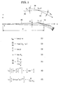
- Fig. 3 shows a view in a plane parallel to the diffraction plane.
- the feature of the equiangular spiral is that an angle ⁇ 0 between a tangential line 38 at any point (x, y) on the equiangular spiral and a line segment 36 that connects the any point (x, y) and the center of spiral (point O) is constant in any point on the spiral. It is the reason why the spiral is called "equiangular" spiral.
- the angle ⁇ 0 is set to be equal to the Bragg angle of Ge(111) for the X-ray wavelength to be used.
- the mirror is made for CuK ⁇ 1, and thus the angle ⁇ 0 is 13.64 degrees.
- the diffracted X-ray (that has been diffracted by the sample) that goes from the point O to the reflective surface is to be incident on the reflective surface 19 with an incidence angle ⁇ 0 to the tangential line 38 of the reflective surface 19 at any incident point on the reflective surface, so that the diffracted X-ray always satisfies the Bragg's condition.
- a reflected X-ray 40 that has reflected at the reflective surface 19 goes out with the angle ⁇ 0 to the tangential line 38 similarly.
- the shape of the reflective surface 19 of the mirror can be determined as described below.
- the center of goniometer point O
- the diffracted X-ray 36 may be expressed by an equation (1) in Fig. 3 , the coordinates (x, y) of each point on the diffracted X-ray track satisfying equation (1).
- y-coordinate of the diffracted X-ray i.e., y DB
- ⁇ and x-coordinate is expressed with the angle ⁇ and x-coordinate.
- Equation (2) A slope dy/dx of the reflective surface 19 at the point (x, y) is expressed by equation (2).
- Equation (2) may be transformed into equation (5) with the use of equations (3) and (4).
- Equation (3) expresses a relationship between x-y coordinates at the point (x, y) and the angle ⁇ .
- Equation (4) defines a tangent of the Bragg angle ⁇ 0 of the mirror as "a”.
- Equation (5) which is a differential equation, is solved to obtain equation (6), which is transformed to equation (7).
- Equation (9) expresses the x-coordinate of any point (x, y) on the reflective surface 19.
- x-coordinate can be calculated with the use of the distance r, the angle ⁇ , and the Bragg angle ⁇ 0 .
- equation (10) which gives y-coordinate.
- a combination of equations (9) and (10) defines the shape of the reflective surface 19 of the mirror.
- a distance ⁇ in y-direction between the tangential line 38 (which is a straight line) of the reflective surface 19 at the center (200, 0) of the reflective surface 19 and the reflective surface 19 (which is a curved line) can be calculated as described below.
- An equation of the tangential line 38 is expressed by equation (11) in Fig. 4 .
- Y-coordinate on the tangential line is defined as y tan .
- y-coordinate of the reflective surface 19 is expressed by equation (10).
- Table 1 shown below indicates the above-described distances ⁇ , which are calculated with the use of the angle ⁇ as a parameter.
- x-coordinate on the reflective surface 19 is 173.099 millimeters and y-coordinate is 6.045 millimeters.
- Y-coordinate on the tangential line 38 at the same x-coordinate, i.e., y tan is 6.528 millimeters. Accordingly, subtracting y-coordinate of the reflective surface 19 from y-coordinate of the tangential line 38 brings 0.483 millimeter, which is the distance ⁇ .
- ⁇ values for ⁇ being one degree, zero degree, negative one degree, and negative two degrees. Since y-coordinate of the reflective surface 19 is always less than y-coordinate of the tangential line when ⁇ is increased and also decreased from zero degree, it is understood that the reflective surface 19 is slightly curved to be concave downward.
- Table 1 ⁇ (°) 2 1 0 -1 -2 x (mm) 173.099 186.092 200 214.882 230.801 y (mm) 6.045 3.248 0 -3.751 -8.060 y tan (mm) 6.528 3.375 0 -3.611 -7.474 ⁇ (mm) 0.483 0.127 0 0.140 0.586
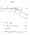
- the diffracted X-ray 36 that travels from the point O in a direction at the angle ⁇ is reflected at the point (x, y) on the reflective surface 19 to become a reflected X-ray 40.
- the diffracted X-ray that travels from the point O along the x-axis is reflected at a point C on the reflective surface 19, the point C being an intersecting point of the reflective surface 19 and the x-axis, to become a reflected X-ray 42.
- the reflected X-ray 42 that has been reflected at the point C is to be called a central beam 42.
- a reflected X-ray 40 that has been reflected at any point (x, y) corresponding to the angle ⁇ will intersect with the central beam 42 before long.
- the intersecting point is defined as a point P.
- a distance between the point C and the point P is defined as t.
- equation (13) an equation of the reflected X-ray 40 that has been reflected at any point (x, y) corresponding to the angle ⁇ is expressed by equation (13).
- Symbol A in equation (13) is defined by equation (12).
- An equation of the central beam 42 is expressed by equation (14).
- An intersecting point P has coordinates that satisfy both equations (13) and (14) at once, and therefore x-coordinate that satisfies the both equations gives x-coordinate of the point P, i.e., x P , which is expressed by equation (15).
- Y-coordinate of the point P, i.e., y P may be calculated, for example, by applying the obtained x P to equation (14).
- Table 2 shown below indicates coordinates (x P , y P ) of the point P and distances t, which are calculated with the use of the angle ⁇ as a parameter, under the condition that r is 200 millimeters and ⁇ 0 is 13.64 degrees. It is understood, according to the table 2, that each reflected X-ray intersects with the central beam at a place approximately 200 millimeters away from the center (point C) of the reflective surface of the mirror. Accordingly, in order to distinctly detect different reflected X-rays that have been reflected at different points on the reflective surface with the position sensitive X-ray detector, it is required to place the position sensitive X-ray detector somewhere between the point C and the point P.
- the position sensitive X-ray detector it is preferable to place the position sensitive X-ray detector at a place approximately 50 to 100 millimeters away from the point C.
- Table 2 ⁇ (°) 2 1 0.5 0.1 0.01 x p (mm) 353.37 365.27 371.44 376.48 377.63 y p (mm) -79.09 -85.23 -88.41 -91.01 -91.60 t (mm) 172.56 185.95 192.89 198.56 199.86 ⁇ (°) -0.01 -0.1 -0.5 -1 -2 x p (mm) 377.88 379.04 384.23 390.85 404.60 y p (mm) -91.73 -92.33 -95.01 -98.42 -105.51 t (mm) 200.14 201.45 207.29 214.73 230.20
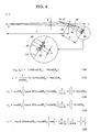
- the detector plane of the position sensitive X-ray detector 20 is placed away from the center (point C) of the reflective surface 19 of the mirror by a distance d.
- the detector plane is arranged nearly perpendicular to the central beam 42.
- the reflected X-ray 40 from the point (x, y) having the angle ⁇ reaches a point Q on the detector plane.
- the central beam 42 from the point C reaches a point M on the detector plane.
- the distance between the point Q and the point M is s. Different reflected X-rays coming from plural different points on the reflective surface of the mirror are to reach plural different points on the X-ray detector respectively.
- the coordinates (x m , y m ) of the point M is expressed by equation (16) in Fig. 6 .
- An equation of a straight line 44 that represents the detector plane is expressed by equation (17).
- the point Q is an intersecting point of the straight line 44 with the reflected X-ray 40. Since the straight line 44 is expressed by equation (17) in Fig. 6 whereas the reflected X-ray 40 is expressed by equation (13) in Fig. 5 , the coordinates (x q , y q ) of the point Q may be obtained by solving the two equations, leading to equations (18) and (19).
- the distance s between the points Q and M may be calculated with the use of equation (16) expressing the coordinates of the point M and equations (18) and (19) both expressing the coordinates of the point Q, leading to equation (20).
- Table 3 shown below indicates distances s on the detector plane, which are calculated with the use of the angle ⁇ as a parameter, under the condition that r is 200 millimeters, ⁇ 0 is 13.64 degrees, and d is 50 millimeters.
- ⁇ is two degrees
- the point Q is 4.28 millimeters away from the point M
- ⁇ is negative two degrees
- the point Q is 6.29 millimeters away from the point M in the opposite direction.
- the lateral size of the detector must be at least about ten millimeters when the detector is placed at a point of 50 millimeters in distance d. If the region of ten millimeters is divided into a hundred channels for example, i.e., 0.1 millimeter per one channel, the diffracted X-ray is to be detected with a positional resolution of about 0.04 degree in a range of four degrees in 2 ⁇ .
- a variation of the angle ⁇ i.e., variation of 2 ⁇
- a characteristic curve of a variation of s to a variation of ⁇ should be prepared based on equation (20) in Fig. 6 , so that it is determined what channel of the detector receives what angle range in ⁇ of an X-ray.
- plural different diffracted X-rays having different diffraction angles can be detected distinctly and simultaneously via the mirror with keeping the one-dimensional position sensitive X-ray detector 20 stationary.
- an X-ray detection intensity can be increased as compared to the case that only a diffracted X-ray having a single diffraction angle is detected at once with the use of the conventional analyzer crystal. Therefore, the present invention enables comparatively short-time diffraction pattern measurement even using the analyzer crystal.
- the receiving optical system 30 should be rotated as shown in Fig. 2 .
Landscapes
- Chemical & Material Sciences (AREA)
- Crystallography & Structural Chemistry (AREA)
- Physics & Mathematics (AREA)
- Health & Medical Sciences (AREA)
- Life Sciences & Earth Sciences (AREA)
- Analytical Chemistry (AREA)
- Biochemistry (AREA)
- General Health & Medical Sciences (AREA)
- General Physics & Mathematics (AREA)
- Immunology (AREA)
- Pathology (AREA)
- Analysing Materials By The Use Of Radiation (AREA)
Claims (4)
- Eine Röntgenbeugungsvorrichtung in der ein paralleler Röntgenstrahl (24) auf eine Probe (26) trifft und wobei gebeugte Röntgenstrahlen (28) von der Probe (26) an einem Spiegel (18), unter Verwendung des Beugungsphänomens, reflektiert werden und danach in einem Röntgendetektor (20) detektiert werden, dadurch gekennzeichnet, dass:der Spiegel (18) eine reflektierende Oberfläche (19) aufweist, die so geformt ist dass ein Winkel in einer Ebene parallel zu der Beugungsebene, zwischen einer tangentialen Linie (38) der reflektierenden Oberfläche (19), an jedem Punkt auf der reflektierenden Oberfläche (19) und einem Liniensegment (36),das jeden der Punkte und die Probe (26) verbindet, konstant wird, und eine Kristallgitterebene die eine Reflektion verursacht parallel zu der reflektierenden Oberfläche (19) an jedem Punkt der reflektierenden Oberfläche (19) ist;der Röntgendetektor (20) eindimensional positionsempfindlich ist in einer Ebene parallel zu der Beugungsebene; undeine relative Positionsbeziehung zwischen dem Spiegel (18) und dem Röntgendetektor (20) bestimmt ist, in einer Ebene parallel zu der Beugungsebene, so dass die reflektierten Röntgenstrahlen (40) von unterschiedlichen Punkten auf der reflektierenden Oberfläche (19) des Spiegels (18) entsprechend unterschiedliche Punkte auf dem Röntgendetektor (20) erreichen.
- Die Röntgenbeugungsvorrichtung nach Anspruch 1, wobei die reflektierende Oberfläche (19) des Spiegels (18) in einer logarithmischen Spirale in einer Ebene parallel zu der Beugungsebene geformt ist, wobei eine Mitte der logarithmischen Spirale auf einer Oberfläche der Probe (26) angeordnet ist.
- Ein Röntgenbeugungsverfahren in dem ein paralleler Röntgenstrahl (24) auf eine Probe (26) trifft und wobei gebeugte Röntgenstrahlen (28) von der Probe (26) an einem Spiegel (18), unter Verwendung des Beugungsphänomens, reflektiert werden und danach in einem Röntgendetektor (20) detektiert werden, dadurch gekennzeichnet, dass:der Spiegel (18) eine reflektierende Oberfläche (19) aufweist, die so geformt ist dass ein Winkel in einer Ebene parallel zu der Beugungsebene, zwischen einer tangentialen Linie (38) der reflektierenden Oberfläche (19), an jedem Punkt auf der reflektierenden Oberfläche (19) und einem Liniensegment (36),das jeden der Punkte und die Probe (26) verbindet, konstant wird, und eine Kristallgitterebene die eine Reflektion verursacht parallel zu der reflektierenden Oberfläche (19) an jedem Punkt der reflektierenden Oberfläche (19) ist;der Röntgendetektor (20) eindimensional positionsempfindlich ist in einer Ebene parallel zu der Beugungsebene; undeine relative Positionsbeziehung zwischen dem Spiegel (18) und dem Röntgendetektor (20) bestimmt ist, in einer Ebene parallel zu der Beugungsebene, so dass die reflektierten Röntgenstrahlen (40) von unterschiedlichen Punkten auf der reflektierenden Oberfläche (19) des Spiegels (18) entsprechend unterschiedliche Punkte auf dem Röntgendetektor (20) erreichen; undunterschiedlich gebeugte Röntgenstrahlen (28), die unterschiedliche Beugungswinkel aufweisen, an dem Spiegel (18) reflektiert werden unddanach getrennt und gleichzeitig durch den Röntgendetektor (20) detektiert werden.
- Das Röntgenbeugungsverfahren nach Anspruch 3, wobei die reflektierende Oberfläche (19) des Spiegels (18) in einer logarithmischen Spirale in einer Ebene parallel zu der Beugungsebene geformt ist, wobei eine Mitte der logarithmischen Spirale auf einer Oberfläche der Probe (26) angeordnet ist.
Priority Applications (1)
| Application Number | Priority Date | Filing Date | Title |
|---|---|---|---|
| EP11000547.7A EP2306179B1 (de) | 2007-09-28 | 2008-08-27 | Röntgenstrahldiffraktionsgerät und -verfahren |
Applications Claiming Priority (2)
| Application Number | Priority Date | Filing Date | Title |
|---|---|---|---|
| JP2007253425A JP4861284B2 (ja) | 2007-09-28 | 2007-09-28 | X線回折装置およびx線回折方法 |
| JP2007253394A JP4861283B2 (ja) | 2007-09-28 | 2007-09-28 | X線回折装置およびx線回折方法 |
Related Child Applications (1)
| Application Number | Title | Priority Date | Filing Date |
|---|---|---|---|
| EP11000547.7 Division-Into | 2011-01-24 |
Publications (3)
| Publication Number | Publication Date |
|---|---|
| EP2042860A2 EP2042860A2 (de) | 2009-04-01 |
| EP2042860A3 EP2042860A3 (de) | 2011-05-04 |
| EP2042860B1 true EP2042860B1 (de) | 2012-07-25 |
Family
ID=40291076
Family Applications (2)
| Application Number | Title | Priority Date | Filing Date |
|---|---|---|---|
| EP08015139A Not-in-force EP2042860B1 (de) | 2007-09-28 | 2008-08-27 | Röntgenstrahldiffraktionsgerät und -verfahren |
| EP11000547.7A Not-in-force EP2306179B1 (de) | 2007-09-28 | 2008-08-27 | Röntgenstrahldiffraktionsgerät und -verfahren |
Family Applications After (1)
| Application Number | Title | Priority Date | Filing Date |
|---|---|---|---|
| EP11000547.7A Not-in-force EP2306179B1 (de) | 2007-09-28 | 2008-08-27 | Röntgenstrahldiffraktionsgerät und -verfahren |
Country Status (3)
| Country | Link |
|---|---|
| US (1) | US7801272B2 (de) |
| EP (2) | EP2042860B1 (de) |
| RU (1) | RU2449262C2 (de) |
Families Citing this family (15)
| Publication number | Priority date | Publication date | Assignee | Title |
|---|---|---|---|---|
| JP4971383B2 (ja) * | 2009-03-25 | 2012-07-11 | 株式会社リガク | X線回折方法及びx線回折装置 |
| CN102472714B (zh) | 2009-07-01 | 2014-08-13 | 株式会社理学 | X射线装置、其使用方法以及x射线照射方法 |
| US9269468B2 (en) * | 2012-04-30 | 2016-02-23 | Jordan Valley Semiconductors Ltd. | X-ray beam conditioning |
| JP6025211B2 (ja) * | 2013-11-28 | 2016-11-16 | 株式会社リガク | X線トポグラフィ装置 |
| WO2017117197A1 (en) * | 2015-12-28 | 2017-07-06 | University Of Washington | Methods for aligning a spectrometer |
| JP6606706B2 (ja) * | 2016-06-24 | 2019-11-20 | 株式会社リガク | 処理方法、処理装置および処理プログラム |
| WO2019006102A1 (en) * | 2017-06-28 | 2019-01-03 | University Of Maryland College Park | SYSTEM AND METHOD FOR REAL-TIME MONITORING BASED ON IN SITU X-RAY DIFFRACTION OF MICROSTRUCTURE PROPERTIES OF PRINTING OBJECTS |
| JP6775777B2 (ja) * | 2017-08-29 | 2020-10-28 | 株式会社リガク | X線回折測定における測定結果の表示方法 |
| JP6954624B2 (ja) * | 2018-02-05 | 2021-10-27 | 日本電気株式会社 | センサ装置 |
| JP2019191168A (ja) | 2018-04-23 | 2019-10-31 | ブルカー ジェイヴィ イスラエル リミテッドBruker Jv Israel Ltd. | 小角x線散乱測定用のx線源光学系 |
| CN112654861B (zh) | 2018-07-05 | 2024-06-11 | 布鲁克科技公司 | 小角度x射线散射测量 |
| CN109374660B (zh) * | 2018-11-22 | 2024-09-06 | 北京科技大学 | 用于排笔光束的高通量粉末衍射的装置 |
| CN114641839B (zh) * | 2019-10-25 | 2025-11-21 | 3M创新有限公司 | 用于无线充电的可变磁性层 |
| US11781999B2 (en) | 2021-09-05 | 2023-10-10 | Bruker Technologies Ltd. | Spot-size control in reflection-based and scatterometry-based X-ray metrology systems |
| US12249059B2 (en) | 2022-03-31 | 2025-03-11 | Bruker Technologies Ltd. | Navigation accuracy using camera coupled with detector assembly |
Family Cites Families (24)
| Publication number | Priority date | Publication date | Assignee | Title |
|---|---|---|---|---|
| EP0024859B1 (de) * | 1979-08-28 | 1985-11-13 | Gec Avionics Limited | Röntgendiffraktometer |
| DE3125803A1 (de) * | 1981-06-30 | 1983-01-13 | Siemens AG, 1000 Berlin und 8000 München | Kristall-roentgen-sequenzspektrometer |
| NL8801019A (nl) * | 1988-04-20 | 1989-11-16 | Philips Nv | Roentgen spectrometer met dubbel gebogen kristal. |
| US4991191A (en) * | 1990-02-05 | 1991-02-05 | The Regents Of The University Of Minnesota | Quantitative analysis of the active table ingredient by power x-ray diffractometry |
| GB2266040B (en) * | 1992-04-09 | 1996-03-13 | Rigaku Ind Corp | X-ray analysis apparatus |
| JP2940757B2 (ja) | 1992-04-09 | 1999-08-25 | 理学電機工業株式会社 | X線回折分析装置 |
| JP2922758B2 (ja) | 1993-08-27 | 1999-07-26 | 理学電機工業株式会社 | X線分光器 |
| JPH0772298A (ja) | 1993-08-31 | 1995-03-17 | Rigaku Ind Co | X線分光器およびx線分光素子 |
| RU2098798C1 (ru) * | 1994-12-08 | 1997-12-10 | Алексей Владиславович Курбатов | Способ получения изображения внутренней структуры объекта с помощью проникающего излучения |
| US5923720A (en) * | 1997-06-17 | 1999-07-13 | Molecular Metrology, Inc. | Angle dispersive x-ray spectrometer |
| US6069934A (en) * | 1998-04-07 | 2000-05-30 | Osmic, Inc. | X-ray diffractometer with adjustable image distance |
| DE19833524B4 (de) * | 1998-07-25 | 2004-09-23 | Bruker Axs Gmbh | Röntgen-Analysegerät mit Gradienten-Vielfachschicht-Spiegel |
| JP3373803B2 (ja) * | 1999-05-28 | 2003-02-04 | 科学技術振興事業団 | コンビナトリアルx線回折装置 |
| US6327334B1 (en) * | 1999-11-18 | 2001-12-04 | Uop Llc | Method of rapidly screening X-ray powder diffraction patterns |
| GB0031040D0 (en) * | 2000-12-20 | 2001-01-31 | Koninkl Philips Electronics Nv | X-ray diffractometer |
| RU2339974C2 (ru) * | 2001-06-19 | 2008-11-27 | Икс-Рэй Оптикал Системз, Инк. | Волновая дисперсивная рентгенофлуоресцентная система с использованием фокусирующей оптики для возбуждения и фокусирующий монохроматор для собирания |
| JP3548556B2 (ja) * | 2001-12-28 | 2004-07-28 | 株式会社リガク | X線回折装置 |
| JP3726080B2 (ja) * | 2002-05-23 | 2005-12-14 | 株式会社リガク | 多結晶材料の配向性の評価方法 |
| JP3731207B2 (ja) * | 2003-09-17 | 2006-01-05 | 株式会社リガク | X線分析装置 |
| TWI328006B (en) * | 2003-12-26 | 2010-08-01 | Nissan Chemical Ind Ltd | Crystal form of quinoline compound and process for its production |
| JP4074874B2 (ja) * | 2005-06-30 | 2008-04-16 | 株式会社リガク | X線回折装置 |
| RU2312602C2 (ru) * | 2005-11-23 | 2007-12-20 | Государственное образовательное учреждение высшего профессионального образования "Московский государственный институт электронной техники" (технический университет) | Способ формирования томографических изображений |
| JP4711430B2 (ja) * | 2006-08-01 | 2011-06-29 | 株式会社リガク | X線回折装置 |
| US7443952B2 (en) * | 2006-10-06 | 2008-10-28 | Rigaku Corporation | X-ray diffraction measurement method and X-ray diffraction apparatus |
-
2008
- 2008-08-13 US US12/190,790 patent/US7801272B2/en not_active Expired - Fee Related
- 2008-08-27 EP EP08015139A patent/EP2042860B1/de not_active Not-in-force
- 2008-08-27 EP EP11000547.7A patent/EP2306179B1/de not_active Not-in-force
- 2008-09-26 RU RU2008138456/28A patent/RU2449262C2/ru not_active IP Right Cessation
Also Published As
| Publication number | Publication date |
|---|---|
| US7801272B2 (en) | 2010-09-21 |
| RU2008138456A (ru) | 2010-04-10 |
| EP2306179A1 (de) | 2011-04-06 |
| RU2449262C2 (ru) | 2012-04-27 |
| US20090086921A1 (en) | 2009-04-02 |
| EP2306179B1 (de) | 2013-06-05 |
| EP2042860A2 (de) | 2009-04-01 |
| EP2042860A3 (de) | 2011-05-04 |
Similar Documents
| Publication | Publication Date | Title |
|---|---|---|
| EP2042860B1 (de) | Röntgenstrahldiffraktionsgerät und -verfahren | |
| EP2233918B1 (de) | Röntgenbeugungsverfahren und Röntgenbeugungsvorrichtung | |
| US8548123B2 (en) | Method and apparatus for using an area X-ray detector as a point detector in an X-ray diffractometer | |
| US9823203B2 (en) | X-ray surface analysis and measurement apparatus | |
| TWI414752B (zh) | 用於分析樣本之裝置及方法 | |
| US6577704B1 (en) | Analysis device which uses X-ray fluorescence | |
| US11885755B2 (en) | X-ray sequential array wavelength dispersive spectrometer | |
| US7076024B2 (en) | X-ray apparatus with dual monochromators | |
| JP4861283B2 (ja) | X線回折装置およびx線回折方法 | |
| US6711232B1 (en) | X-ray reflectivity measurement | |
| US7113566B1 (en) | Enhancing resolution of X-ray measurements by sample motion | |
| EP1396716B1 (de) | Röntgenstrahlungsoptik für Kleinwinkelstreuungsmessungen | |
| JP3726080B2 (ja) | 多結晶材料の配向性の評価方法 | |
| US20250277764A1 (en) | X-ray diffraction apparatus and measurement method | |
| JP6009156B2 (ja) | 回折装置 | |
| JPH0374360B2 (de) | ||
| JP3968350B2 (ja) | X線回折装置及び方法 | |
| TWI329736B (en) | X-ray scattering with a polychromatic source | |
| Jagodziński et al. | A DuMond-type crystal spectrometer for synchrotron-based X-ray emission studies in the energy range of 15–26 keV | |
| JP4861284B2 (ja) | X線回折装置およびx線回折方法 | |
| JPH05196583A (ja) | 全反射x線分析装置 | |
| US8744046B2 (en) | Method and apparatus of precisely measuring intensity profile of X-ray nanobeam | |
| JP2002350368A (ja) | X線吸収微細構造測定方法および測定装置 | |
| JPH06160312A (ja) | X線評価装置 | |
| JP2006133000A (ja) | 微小部積層構造検査装置 |
Legal Events
| Date | Code | Title | Description |
|---|---|---|---|
| PUAI | Public reference made under article 153(3) epc to a published international application that has entered the european phase |
Free format text: ORIGINAL CODE: 0009012 |
|
| AK | Designated contracting states |
Kind code of ref document: A2 Designated state(s): AT BE BG CH CY CZ DE DK EE ES FI FR GB GR HR HU IE IS IT LI LT LU LV MC MT NL NO PL PT RO SE SI SK TR |
|
| AX | Request for extension of the european patent |
Extension state: AL BA MK RS |
|
| 17P | Request for examination filed |
Effective date: 20110128 |
|
| PUAL | Search report despatched |
Free format text: ORIGINAL CODE: 0009013 |
|
| AK | Designated contracting states |
Kind code of ref document: A3 Designated state(s): AT BE BG CH CY CZ DE DK EE ES FI FR GB GR HR HU IE IS IT LI LT LU LV MC MT NL NO PL PT RO SE SI SK TR |
|
| AX | Request for extension of the european patent |
Extension state: AL BA MK RS |
|
| AKX | Designation fees paid |
Designated state(s): DE FR GB |
|
| GRAP | Despatch of communication of intention to grant a patent |
Free format text: ORIGINAL CODE: EPIDOSNIGR1 |
|
| GRAS | Grant fee paid |
Free format text: ORIGINAL CODE: EPIDOSNIGR3 |
|
| GRAA | (expected) grant |
Free format text: ORIGINAL CODE: 0009210 |
|
| AK | Designated contracting states |
Kind code of ref document: B1 Designated state(s): DE FR GB |
|
| REG | Reference to a national code |
Ref country code: GB Ref legal event code: FG4D |
|
| REG | Reference to a national code |
Ref country code: DE Ref legal event code: R096 Ref document number: 602008017348 Country of ref document: DE Effective date: 20120920 |
|
| PLBE | No opposition filed within time limit |
Free format text: ORIGINAL CODE: 0009261 |
|
| STAA | Information on the status of an ep patent application or granted ep patent |
Free format text: STATUS: NO OPPOSITION FILED WITHIN TIME LIMIT |
|
| 26N | No opposition filed |
Effective date: 20130426 |
|
| REG | Reference to a national code |
Ref country code: DE Ref legal event code: R097 Ref document number: 602008017348 Country of ref document: DE Effective date: 20130426 |
|
| REG | Reference to a national code |
Ref country code: FR Ref legal event code: PLFP Year of fee payment: 8 |
|
| PGFP | Annual fee paid to national office [announced via postgrant information from national office to epo] |
Ref country code: DE Payment date: 20150831 Year of fee payment: 8 Ref country code: GB Payment date: 20150826 Year of fee payment: 8 |
|
| PGFP | Annual fee paid to national office [announced via postgrant information from national office to epo] |
Ref country code: FR Payment date: 20150811 Year of fee payment: 8 |
|
| REG | Reference to a national code |
Ref country code: DE Ref legal event code: R119 Ref document number: 602008017348 Country of ref document: DE |
|
| GBPC | Gb: european patent ceased through non-payment of renewal fee |
Effective date: 20160827 |
|
| REG | Reference to a national code |
Ref country code: FR Ref legal event code: ST Effective date: 20170428 |
|
| PG25 | Lapsed in a contracting state [announced via postgrant information from national office to epo] |
Ref country code: GB Free format text: LAPSE BECAUSE OF NON-PAYMENT OF DUE FEES Effective date: 20160827 Ref country code: DE Free format text: LAPSE BECAUSE OF NON-PAYMENT OF DUE FEES Effective date: 20170301 Ref country code: FR Free format text: LAPSE BECAUSE OF NON-PAYMENT OF DUE FEES Effective date: 20160831 |