EP2042956A2 - Interface entre un système de gestion de la fabrication et un système d'automatisation - Google Patents
Interface entre un système de gestion de la fabrication et un système d'automatisation Download PDFInfo
- Publication number
- EP2042956A2 EP2042956A2 EP08016419A EP08016419A EP2042956A2 EP 2042956 A2 EP2042956 A2 EP 2042956A2 EP 08016419 A EP08016419 A EP 08016419A EP 08016419 A EP08016419 A EP 08016419A EP 2042956 A2 EP2042956 A2 EP 2042956A2
- Authority
- EP
- European Patent Office
- Prior art keywords
- data
- interface
- long
- gds
- term
- Prior art date
- Legal status (The legal status is an assumption and is not a legal conclusion. Google has not performed a legal analysis and makes no representation as to the accuracy of the status listed.)
- Granted
Links
Images


Classifications
-
- G—PHYSICS
- G05—CONTROLLING; REGULATING
- G05B—CONTROL OR REGULATING SYSTEMS IN GENERAL; FUNCTIONAL ELEMENTS OF SUCH SYSTEMS; MONITORING OR TESTING ARRANGEMENTS FOR SUCH SYSTEMS OR ELEMENTS
- G05B19/00—Program-control systems
- G05B19/02—Program-control systems electric
- G05B19/418—Total factory control, i.e. centrally controlling a plurality of machines, e.g. direct or distributed numerical control [DNC], flexible manufacturing systems [FMS], integrated manufacturing systems [IMS] or computer integrated manufacturing [CIM]
- G05B19/4185—Total factory control, i.e. centrally controlling a plurality of machines, e.g. direct or distributed numerical control [DNC], flexible manufacturing systems [FMS], integrated manufacturing systems [IMS] or computer integrated manufacturing [CIM] characterised by the network communication
-
- G—PHYSICS
- G05—CONTROLLING; REGULATING
- G05B—CONTROL OR REGULATING SYSTEMS IN GENERAL; FUNCTIONAL ELEMENTS OF SUCH SYSTEMS; MONITORING OR TESTING ARRANGEMENTS FOR SUCH SYSTEMS OR ELEMENTS
- G05B2219/00—Program-control systems
- G05B2219/10—Plc systems
- G05B2219/14—Plc safety
- G05B2219/14055—Make log, journal, history file of state changes
-
- G—PHYSICS
- G05—CONTROLLING; REGULATING
- G05B—CONTROL OR REGULATING SYSTEMS IN GENERAL; FUNCTIONAL ELEMENTS OF SUCH SYSTEMS; MONITORING OR TESTING ARRANGEMENTS FOR SUCH SYSTEMS OR ELEMENTS
- G05B2219/00—Program-control systems
- G05B2219/20—Pc systems
- G05B2219/24—Pc safety
- G05B2219/24055—Trace, store a working, operation history
-
- G—PHYSICS
- G05—CONTROLLING; REGULATING
- G05B—CONTROL OR REGULATING SYSTEMS IN GENERAL; FUNCTIONAL ELEMENTS OF SUCH SYSTEMS; MONITORING OR TESTING ARRANGEMENTS FOR SUCH SYSTEMS OR ELEMENTS
- G05B2219/00—Program-control systems
- G05B2219/30—Nc systems
- G05B2219/31—From computer integrated manufacturing till monitoring
- G05B2219/31174—Load, use different protocols, formats, emulators for different systems
-
- G—PHYSICS
- G05—CONTROLLING; REGULATING
- G05B—CONTROL OR REGULATING SYSTEMS IN GENERAL; FUNCTIONAL ELEMENTS OF SUCH SYSTEMS; MONITORING OR TESTING ARRANGEMENTS FOR SUCH SYSTEMS OR ELEMENTS
- G05B2219/00—Program-control systems
- G05B2219/30—Nc systems
- G05B2219/31—From computer integrated manufacturing till monitoring
- G05B2219/31337—Failure information database
-
- G—PHYSICS
- G05—CONTROLLING; REGULATING
- G05B—CONTROL OR REGULATING SYSTEMS IN GENERAL; FUNCTIONAL ELEMENTS OF SUCH SYSTEMS; MONITORING OR TESTING ARRANGEMENTS FOR SUCH SYSTEMS OR ELEMENTS
- G05B2219/00—Program-control systems
- G05B2219/30—Nc systems
- G05B2219/31—From computer integrated manufacturing till monitoring
- G05B2219/31369—Translation, conversion of protocol between two layers, networks
-
- G—PHYSICS
- G05—CONTROLLING; REGULATING
- G05B—CONTROL OR REGULATING SYSTEMS IN GENERAL; FUNCTIONAL ELEMENTS OF SUCH SYSTEMS; MONITORING OR TESTING ARRANGEMENTS FOR SUCH SYSTEMS OR ELEMENTS
- G05B2219/00—Program-control systems
- G05B2219/30—Nc systems
- G05B2219/31—From computer integrated manufacturing till monitoring
- G05B2219/31372—Mes manufacturing execution system
-
- G—PHYSICS
- G05—CONTROLLING; REGULATING
- G05B—CONTROL OR REGULATING SYSTEMS IN GENERAL; FUNCTIONAL ELEMENTS OF SUCH SYSTEMS; MONITORING OR TESTING ARRANGEMENTS FOR SUCH SYSTEMS OR ELEMENTS
- G05B2219/00—Program-control systems
- G05B2219/30—Nc systems
- G05B2219/31—From computer integrated manufacturing till monitoring
- G05B2219/31395—Process management, specification, process and production data, middle level
-
- G—PHYSICS
- G05—CONTROLLING; REGULATING
- G05B—CONTROL OR REGULATING SYSTEMS IN GENERAL; FUNCTIONAL ELEMENTS OF SUCH SYSTEMS; MONITORING OR TESTING ARRANGEMENTS FOR SUCH SYSTEMS OR ELEMENTS
- G05B2219/00—Program-control systems
- G05B2219/30—Nc systems
- G05B2219/35—Nc in input of data, input till input file format
- G05B2219/35291—Record history, log, journal, audit of machine operation
-
- Y—GENERAL TAGGING OF NEW TECHNOLOGICAL DEVELOPMENTS; GENERAL TAGGING OF CROSS-SECTIONAL TECHNOLOGIES SPANNING OVER SEVERAL SECTIONS OF THE IPC; TECHNICAL SUBJECTS COVERED BY FORMER USPC CROSS-REFERENCE ART COLLECTIONS [XRACs] AND DIGESTS
- Y02—TECHNOLOGIES OR APPLICATIONS FOR MITIGATION OR ADAPTATION AGAINST CLIMATE CHANGE
- Y02P—CLIMATE CHANGE MITIGATION TECHNOLOGIES IN THE PRODUCTION OR PROCESSING OF GOODS
- Y02P90/00—Enabling technologies with a potential contribution to greenhouse gas [GHG] emissions mitigation
- Y02P90/02—Total factory control, e.g. smart factories, flexible manufacturing systems [FMS] or integrated manufacturing systems [IMS]
Definitions
- the invention relates to an interface between a production management system (MES) and an automation system and to a method for operating such an interface according to claims 1 and 15.
- MES production management system
- Dynamic Data Exchange was the predestined interface for exchanging information between software applications.
- OPC has now become the standardized interface for the exchange of process data in PC-based automation technology.
- OPC is an application of the Microsoft Distributed Component Object Modeling (DCOM) technology.
- DCOM Microsoft Distributed Component Object Modeling
- OPC-based data exchange is characterized by significantly higher performance.
- OPC server By equipping an automation system with an OPC server, secure communication with higher-level control systems can be achieved. Since there is no standardized communication interface in many automation system components, the connection of this communication interface to an MES on the part of the user involves a high programming effort in that the commands provided by the automation system component for parameterizing the component are converted into a format that can be read and written by the MES have to.
- the supplier of the MES could also supply a component-specific connection.
- the MES system is inflexible and the automation components can only be exchanged for components from other manufacturers with great programming effort. Also for the manufacturer of the manufacturing management system is The effort is higher because he has to provide different interface modules for different automation components to his customers.
- the Utility Model DE 202 80 020 U1 discloses a welder with OPC server with a data processing program for converting internal data of the welder from an internal data format to the OPC standard format and / or vice versa.
- the OPC server comprises measurement / output means for acquiring internal data, wherein the OPC server is in communication with an OPC interface and wherein the OPC interface is arranged on a housing of the welding device.
- the welding machine can be exchanged very easily with welding machines from other manufacturers, which also use the OPC standard format.
- the OPC server can record internal operating states of the welding device and conditionally process them using the OPC interface OPC and then forward them, but requires the higher-level system (eg MES) to evaluate the data.
- MES higher-level system
- the object of the invention is to provide an interface which, in addition to a uniform connection of an automation system component to a production management system, also makes it possible to relieve the manufacturing management system of its computing capacity.
- the advantage of the solution according to the invention over the initially mentioned prior art is that by means of the long-term data memory changes of operating parameters of an automation component connected to the device can be logged over a longer period of time.
- buffers for data volumes of up to 10 terabytes can be provided.
- the data analysis unit it is possible during or after the buffering to examine the data logged by means of the second interface and to derive therefrom findings relating to the state of the automation component.
- the results generated by the data analysis means can then be stored in the long-term memory or cached, as well as forwarded by means of one of the interfaces to a connected system, after they have been prepared according to the data protocol to be used.
- a production management system which usually takes over the data update, relieved in terms of the required computing power.
- the device thus serves, on the one hand, as an interface for the exchange of data between two systems which use different communication protocols and, on the other hand, primarily still has the function of a control entity, which components connected to the device, such as programmable logic controllers (PLC), numerical controls (NC), drive controllers and motors, monitored with respect to their operating state, analyzed their operating state, and the parent system communicates this operating state, possibly together with the analysis result.
- PLC programmable logic controllers
- NC numerical controls
- drive controllers and motors monitored with respect to their operating state, analyzed their operating state, and the parent system communicates this operating state, possibly together with the analysis result.
- operating parameters of an automation system component connected to the device can be changed during operation by means of the second interface and thus corrected at runtime ("on the fly").
- the long-term data memory could also serve as a data buffer for the data analysis unit, wherein analysis results or intermediate analysis results can be stored in the long-term data memory and read out again from the long-term data memory and further processed by the data analysis unit.
- the data from the long-term data memory can be retrieved from this higher-level system by means of a superordinate system which can be connected to the first interface; it would also be conceivable to make the data storage retrievable by an automation component connected to the second interface.
- a machine-near long-term recording of process and machine status data is possible. Due to the realizable long-term recording, data can be made available for the exact analysis of the cause of problems on machines, for the optimization of products (eg components of a machine tool) and for the optimization of process sequences. Due to the evaluation algorithms that can be integrated into the device according to the invention, the user can concentrate on the optimization and analysis of the machine behavior and / or the production process and need not worry about how he establishes the data connection to the machine and to higher-level systems.
- the device according to the invention comprises a data analysis unit with at least one exchangeable functional unit, by means of which the function of the data analysis unit can be defined and changed at any time and which is managed by means of the configuration means.
- the device can thus modify the function of the data analysis means by exchanging the analysis algorithms for the operating parameters read into the long-term memory in an application-specific and case-specific manner.
- the function is preferably implemented by means of a hardware and / or software plug-in (exchangeable hardware and / or software component).
- the hardware plug-in could, for example, be realized by means of an exchangeable storage medium which, on the basis of the user program stored on it, defines the function of the data analysis unit and can be activated by means of the configuration means.
- Another possibility would be to provide or read in software modules, for example by means of a memory included in the device. Existing or special interfaces could be provided for both the hardware plug-in and the software plug-in.
- the data analysis unit has immediate access to the data acquisition means and / or the data transfer means and / or the data acquisition means immediate access to the data transfer means and the data analysis unit.
- data reception and analysis could be done in real time, bypassing the data buffer.
- the data transmission means additionally has direct access to the long-term data memory, so that the data is transferred without intermediate steps from the Memory or data collection means can be read and processed for forwarding.
- a data protection device is included, by means of which a backup of the data to be transmitted by means of a secure data protocol can be realized. This can be used to prevent erroneous data from being transmitted and to give third parties insight into the data when using non-secure network connections.
- the first interface uses as the first data protocol the OPC UA standard with XML data format or web service standard and the second interface as the second data protocol a fieldbus standard or also the OPC UA standard, but with a binary data format.
- the OPC UA standard with XML data format or Web service standard serves as the standardized interface to the production management system, and the OPC UA standard with binary data format as a standardized interface to the automation component. This configuration allows easy replacement of automation components monitored by a manufacturing management system.
- the device is implemented as a server which functions as a standardized interface between a production monitoring system designed as a client and an automation system component and is realized in particular by means of a personal computer which is connected to the higher-level system and to the automation system component by means of hardware interface cards.
- the device can then be realized purely software based using the hardware of a standard PC, which makes the solution cheap and flexible.
- a drive system with an integrated device according to the invention or external device, wherein the automation system component is a programmable logic controller (PLC) or a numerical control (CNC, NC) or a motion control (Motion Control) or an electric drive (Drive) can by means of the invention easily connected to a higher-level management system.
- PLC programmable logic controller
- CNC numerical control
- Motion Control Motion Control
- Drive electric drive
- a machining system, in particular machine tools, with integrated or external device according to the invention, which is connected by means of the second interface to an automation system component which is part of the machining system has the advantage that worn components can be replaced early and the personnel responsible for the machining system can be informed in good time about the cause of the error before it comes to a failure of the processing system.
- automation components can be easily replaced.
- the invention is particularly advantageous if many automation components, for example in the context of an assembly line, are to be managed and monitored, because this can be done by means of the invention both centralized or at least partially centralized.
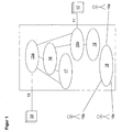
- the device according to the invention is shown in the form of a so-called generic, preferably PC-based, data server (GDS).
- the GDS comprises a first interface 11 for connecting the production management system (MES) 12 to the GDS by means of the OPC-UA XML data protocol and a second interface 13 for connecting the automation system component (eg PLC, NC, drive controller) 14 to the GDS by means of the OPC -UA binary data protocol, wherein a data acquisition means 15a and a data transfer means 15b are included, which are respectively connected to at least one of the interfaces 11, 13 and which are additionally interconnected such that a Communication between the connectable to the interface 11, 13 systems 12, 14 is realized, wherein a data converting means (not shown) is included by the GDS, which the protocols of both interfaces into each other, wherein additionally in the GDS a long-term data memory 16 for the storage of means of the data acquisition means 15a, raw data data, in particular of operating parameters of the automation system component 14, is integrated.
- MES production management system
- a data analysis unit 17 integrated in the GDS for analyzing the raw data stored in the long-term data memory 16 is integrated. Furthermore, there is also a configuration means 18 of the GDS, which is used for the configuration of the data analysis unit 17 with respect to the analysis to be performed and for the configuration of the GDS itself, in particular for the configuration with regard to the manner of further processing the result of the data analysis using one of the interfaces 11, 13 or by means of the long-term data memory 16.
- GDS generic data server
- All data processing methods known in the state of the art are conceivable which are suitable for statistical purposes or other analyzes of the data.
- Special user-specific implemented analysis methods could also be loaded into the data analysis unit 17 by means of a special replaceable function module.
- the data analysis unit 17 can also directly (not via the long-term data memory 16) directly receive and process the data acquired by means of the data acquisition means 15a.
- the data transmission means 15b is directly connected to the long-term data memory 16 and the data acquisition means 15a.
- the data transfer means 15b has access, directly or indirectly, to the components 15a, 16, 17. It is therefore possible both in the long-term data memory 16, and data received from the data acquisition means 15a and data analyzed by the data analysis unit 17 by means of the data transmission means 15b to the MES 12 by means of suitable protocols or data structures (eg Web Services, OPC UA XML, OPC UA binary).
- the MES 12 thus communicates indirectly by means of the internal structure 15a, b, 16, 17 of the GDS with the automation component 14 GDS using the configuration means 18 to configure that a data protection device 19 is active, which protects the data transfer and is suitable for the allocation of access rights, wherein different operators 10a, 10b, 10c of the GDS and / or higher-level systems different access rights can be granted.
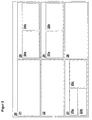
- FIG. 2 an embodiment of the GDS 20 with integrated proxy function component 21 is shown, which has the task between the GDS 20 and an external network (eg WAN, Internet, etc.) to ensure a communication connection.
- the GDS 20 includes a communication functional component 22, by means of which the communication with a higher-level system takes place directly or indirectly by means of the proxy function component 21.
- the data collection function component 23 integrated in the GDS 20 includes a means 23a for receiving data, a control program 23b, and a data storage means 23c.
- the access control 24 integrated in the GDS 20 includes a secure data transfer configuration component 24a (e.g., selection of encryption algorithms, VPN, secure protocols) depending on the local or external network attached.
- the GDS integrated access control 24 also includes a component for configuring user rights 24b, for example, to assign and manage the access rights of users of the GDS 20.
- the GDS 20 comprises a basic configuration configuration means 25a and connection-specific configurations 25b for connections between GDS and a higher-level system.
- measuring points for detecting operating states of an automation component connected to the GDS can be defined, for example, by assigning PLC or NC variables or inputs or outputs on a PLC (programmable logic controller) or NC (numerical control) to a customer-specific context. It is also possible to define data protocols for the GDS interfaces and to implement the connection of systems connected to the GDS, for example by assigning IP addresses.
- the commissioning of the server serves to connect the automation components of machining centers to the GDS in such a way that they can be specifically addressed by means of a standardized command, so that preferably several machining centers can be managed by the MES.
- the GDS includes a configuration tool, such as a software browser or an application that uses an existing Internet browser.
- a previously defined measuring point is selected by means of the browser and the measuring point so-called identifier for unambiguous identification of the measuring point are assigned, so that the measuring point can be accessed later by means of the identifier.
- identifier for unambiguous identification of the measuring point
- the data structure for a measurement series could also be integrated in the measurement point browser. Due to these measures, the data structure of the measurement series is clearly defined.
- own identifiers are assigned to one or more data points to be described.
- the data points can be addressed by means of the identifiers.
- Data points could be, for example, input units of automation components. It is also possible to copy or save previously created identifiers for data points.
- the time is determined when the writing takes place, i. when the data points are described by means of the identifiers. For this it is necessary to define the conditions for the writing process.
- GDS 20 is additionally comprises a preprocessing unit for data.
- preprocessing unit was chosen because the preprocessing can be used to optimize the communication between GDS and MES and thus relieve the MES.
- the actual processing of the data in the sense of a control station or process control continues, for example, with the MES.
- the configuration of a processing operation may include the following steps:
- measurement data can be grouped. It can be determined where in the GDS evaluation results are to be stored (database, file system) and whether, or to which addressee, a notification regarding existing calculation results should be sent.
- the memory size e.g., n data bytes in a ring buffer
- the type of data processing is defined, for example by selecting a suitable algorithm, for example for calculating an average value, for calculating minimum or maximum values or for performing a Fourier transformation.
- a suitable algorithm for example for calculating an average value, for calculating minimum or maximum values or for performing a Fourier transformation.
- Certain inputs and / or outputs of an automation system component connected to the GDS can be specifically linked to an algorithm so that different algorithms for different operating parameters of the automation component are used. It is also possible to validate the correct interconnection as part of the processing, for example with regard to the data types and the amount of data, such as the minimum number of input values.
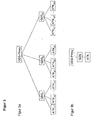
- FIG. 3a shows a network with multiple GDS.
- Each GDS1 to GDSm can in turn have several automation components ATK11 to ATKmn be connected by means of a corresponding data protocol (eg OPC UA binary).
- the points between GDS2 and GDSm should make it clear that the in FIG. 3 Theoretically, the network shown can be extended as desired and further GDS can be inserted here.
- the components are connected to each other here in a star shape. All GDSs are connected by means of a transmission link to a superordinate GDS proxy, with the GDS proxy allowing connection to a higher-level network.
- FIG. 3b shows the simplest form of realization and in principle represents only a single branch of the FIG. 3a
- an automation component ATK is shown, which communicates by means of a secure data protocol with the GDS and this in turn with the GDS proxy.
- the GDS proxy has the task of managing Internet addresses or network addresses and connecting the local network with the generic data servers GDS1 to GDSm to the Internet.
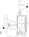
- the monitoring of the automation component is represented by means of the GDS according to the invention, in particular the sequence of a measuring operation on the I / O unit of an automation component (eg PLC, NC) using the GDS.
- the GDS comprises an integrated data receiving means 23a with a control program 23b. It will be on the in FIG. 2 Components described here each reference.
- the control program 23b plays a central role in the course of the measuring process. As soon as a change has been made from a current operating state 400 (for example, initial operating state: GDS started and configured) of the GDS to the operating state measured data processing 401, this waits Control program 23b to an external event 402.
- the external event 402 could be, for example, a falling or rising edge on an I / O unit of the automation component and is configurable on the GDS. If the external event 402 occurs, the control program 23b initiates the reception of data in a next step 403, whereby the current value of a previously defined measurement point (I / O unit) is read in at the automation system component in step 404.
- the further procedure can now be carried out as follows by means of implemented branches 410:
- the read-in measured value is either relevant ("to report”) because, for example, it exceeds a predetermined threshold value and must be observed or stored. Or the read-in reading is not relevant ("do not report”) and does not need to be considered or saved. If the measured value has to be taken into account, it is prepared for transfer to the higher-level system 405 by being integrated into a data protocol (eg OPC-UA-XML) suitable for the first interface and transmitted to the higher-level system 406. Alternatively or additionally the reading may be off FIG. 2 known data storage means 23c are passed and stored there (407, 408).
- a data protocol eg OPC-UA-XML
- a further branch 410 it is decided by means of a further branch 410 whether further measurements (“continue to measure”) are carried out or the measurement is ended (“end measurement”), so that a new operating mode 409 can be assumed (eg operating state: "server stop” or " Measurement data acquisition completed ").
- the GDS comprises an integrated data collecting means 23 with a data acquisition means 23a, a control program 23b and a data memory 23c. It gets up in this regard FIG. 2 and the related explanation above referenced.
- the control program 23b waits for an external event 502.
- the external event 502 could be, for example, a setpoint specification of a user at the higher-level system , Which external event 502 the control program 23b responds to and how it reacts can be configured by means of the configuration means 25 of the GDS.
- the control program 23b initiates the reception of data by means of the data acquisition means 23a, whereby data is written to a data point in the GDS in the following step 504.
- the term data point is understood, for example, as a process parameter or machine parameter whose nominal value can be changed.
- step 504 the program logic branches such that both one of the interfaces of the GDS (see FIG. 1 with description) as well as the data memory 23c (see FIG. 2 with description) of the GDS can be used as data sink.
- the data acquisition means 23a transfers the currently acquired data to one of the interfaces by means of step 505, as long as the data satisfy the necessary criteria. If step 505 has been executed, the data is sent in a subsequent step 506 via the interface.
- the interface could be, for example, the first interface 11 of the GDS, to which an MES 12 is connected, being communicated with the MES 12, for example by means of an Internet protocol.
- Operation state 509 eg operating state: "server is stopped”
- it is again branched back to step 501, so that the control program 23b as described above continues to wait for an event, which was defined by step 502.
- the data acquisition means 23a transfers the data by means of the second branch as part of the program step 507 to the data buffer or to the data memory 23c.
- Decision points 510 decide whether or not to save (step 508).
- FIG. 6 the logical flow for a GDS initiated processing is shown. It is in this regard again FIG. 2 and the related explanation above referenced.
- the control program of the processor waits for a defined external event 602.
- the user requests an evaluation of acquired measured data by means of the he can, for example, from the measurement data of a circularity test can determine the "backlash" by the data preprocessing unit 26.
- the data pre-processing unit 26 reads out data from the data memory 23 c in a second processing step 604 and carries out a data analysis or calculations in consideration of the data as part of a third processing step 605.
- the data calculation unit 26 comprises at least one exchangeable functional unit by means of which the algorithm can be defined for the data analysis. By means of the decision points 614 the further course is determined. If the data underlying the analysis is to be written to a data point, the data preprocessing unit 26 transfers the result of the calculation to the latter in the context of the processing step 607 FIG. 2 known data receiving means 23a, which is then initiated in the context of the processing step 608, the actual writing operation of the data to the data point.
- step 608 the program logic branches such that both one of the interfaces of the GDS (see FIG. 1 with description) as well as the data memory 23c (see FIG. 2 with description) of the GDS could be used as data sink.
- the data calculation unit 26 transfers the currently acquired data to one of the interfaces by means of step 609. If step 609 has been carried out, the data is sent in a subsequent step 610 by means of one of the interfaces of the GDS.
- the interface could, for example, be the first interface 11 of the GDS, to which an MES 12 is connected, with the MES 12 being communicated by means of an Internet protocol and the data being transferred by means of this protocol.
- the processing operation is ended and moved to another operating state 613 (eg operating state: server is stopped) or it is again branched back to step 601, so that the control program 23b, as described above, continues to wait for an event, which was defined by step 602.
- the preprocessing unit 26 transfers the data by means of the second branch in the context of the program step 611 to the data buffer or the data memory 23 c and stores it there in the context of step 612 depending on the state of the decision points 614.
- FIG. 7 again shows some of the description of the figures FIG. 2 already known components and their mutual interaction during the operation of the GDS, especially during the in the FIGS. 4 to 6 shown and previously described program flows. It was the FIG. 2 known reference numbers used here again. In addition, measuring points / monitor data 71 and recordable data points 72 are shown.
- the communication functional component 22 comprises communication interfaces (web services, OPC-UA XML, OPC-UA binary) to which the data acquisition means 23a of the data collection function component 23 have access, so that data from the data acquisition means 23a is sent by the control program 23b from the preprocessing unit 26 to the Communication interfaces of the communication component 22 can be transmitted.
- the communication component 22 can also transmit data transmitted from the external peripherals to the server via the communication interfaces indirectly to the data acquisition means 23a by means of the control program 23b.
- the data memory 23c can comprise both structured measurement series 23c1 and conditioned measurement data 23c2.
- the data for storing structured measurement series is received by the data memory 23c from the data acquisition means 23a, wherein the preprocessing unit 26 can read out these measurement series.
- the data memory 23c receives conditioned measurement data, for example, from the preprocessing unit 26.
- the data memory 23c serves as a kind of buffer or memory for intermediate results, wherein the preprocessing unit 26 can store and read out these intermediate results here as well.
- the data acquisition means 23a can read data from the measurement points 71 once or regularly (monitor operation) and write data points 72 once or regularly.
- the data acquisition means 23a has access to the data memory 23c, in particular to the memory area 23c1 for storing structured measurement series.
- the steps and data transfers described above can be partially processed simultaneously or sequentially by the GDS.
Landscapes
- Engineering & Computer Science (AREA)
- General Engineering & Computer Science (AREA)
- Manufacturing & Machinery (AREA)
- Quality & Reliability (AREA)
- Physics & Mathematics (AREA)
- General Physics & Mathematics (AREA)
- Automation & Control Theory (AREA)
- Management, Administration, Business Operations System, And Electronic Commerce (AREA)
- General Factory Administration (AREA)
- Programmable Controllers (AREA)
- Arrangements For Transmission Of Measured Signals (AREA)
- Computer And Data Communications (AREA)
Applications Claiming Priority (1)
| Application Number | Priority Date | Filing Date | Title |
|---|---|---|---|
| DE102007045926A DE102007045926A1 (de) | 2007-09-26 | 2007-09-26 | Schnittstelle zwischen einem Fertigungsmanagementsystem und einem Automatisierungssystem |
Publications (3)
| Publication Number | Publication Date |
|---|---|
| EP2042956A2 true EP2042956A2 (fr) | 2009-04-01 |
| EP2042956A3 EP2042956A3 (fr) | 2010-07-07 |
| EP2042956B1 EP2042956B1 (fr) | 2019-02-27 |
Family
ID=40160783
Family Applications (1)
| Application Number | Title | Priority Date | Filing Date |
|---|---|---|---|
| EP08016419.7A Active EP2042956B1 (fr) | 2007-09-26 | 2008-09-18 | Interface entre un système de gestion de la fabrication et un système d'automatisation |
Country Status (3)
| Country | Link |
|---|---|
| US (1) | US8352536B2 (fr) |
| EP (1) | EP2042956B1 (fr) |
| DE (1) | DE102007045926A1 (fr) |
Cited By (5)
| Publication number | Priority date | Publication date | Assignee | Title |
|---|---|---|---|---|
| WO2010118863A1 (fr) * | 2009-04-17 | 2010-10-21 | Robert Bosch Gmbh | Procédé de préparation de données d'état de processus et/ou de données d'état de machine d'une machine-outil |
| WO2011066900A1 (fr) * | 2009-12-03 | 2011-06-09 | Robert Bosch Gmbh | Communication entre des éléments d'un système |
| CN103370665A (zh) * | 2010-12-04 | 2013-10-23 | 罗伯特·博世有限公司 | 用于运行作业机器的方法和作业机器 |
| CN103499951A (zh) * | 2013-09-13 | 2014-01-08 | 中国石油天然气股份有限公司 | 一种基于Web架构的抽油机动态调平衡系统 |
| CN106597991A (zh) * | 2016-12-12 | 2017-04-26 | 北京兰光创新科技有限公司 | 数控机床远程监控方法及装置 |
Families Citing this family (8)
| Publication number | Priority date | Publication date | Assignee | Title |
|---|---|---|---|---|
| WO2011147652A1 (fr) * | 2010-05-25 | 2011-12-01 | Siemens Aktiengesellschaft | Procédé et dispositif d'échange de données ainsi que réseau |
| US9106678B2 (en) * | 2010-05-25 | 2015-08-11 | Siemens Aktiengesellschaft | Method and apparatus for interchanging data between two devices in an automation network |
| US20120035749A1 (en) * | 2010-08-04 | 2012-02-09 | Fisher-Rosemount Systems, Inc. | Seamless integration of process control devices in a process control environment |
| DE102011005062A1 (de) * | 2011-03-03 | 2012-09-06 | Endress + Hauser Process Solutions Ag | Verfahren zum Bereitstellen von Daten eines Feldgeräts |
| US10317858B2 (en) * | 2011-04-07 | 2019-06-11 | Infosys Technologies, Ltd. | Architecture and method for centrally controlling a plurality of building automation systems |
| DE102017202360A1 (de) * | 2017-02-14 | 2018-08-16 | Deckel Maho Pfronten Gmbh | Datenschnittstellenvorrichtung zum einsatz an einer numerisch gesteuerten werkzeugmaschine |
| DE102020122403A1 (de) | 2020-08-27 | 2022-03-03 | Homag Gmbh | Produktionssystem und Verfahren zum Betreiben eines Produktionssystems |
| DE102024208098A1 (de) | 2024-08-26 | 2026-02-26 | Robert Bosch Gesellschaft mit beschränkter Haftung | Verfahren und Vorrichtung zur automatisierten Konfiguration von Manufacturing Execution Systeme |
Citations (1)
| Publication number | Priority date | Publication date | Assignee | Title |
|---|---|---|---|---|
| DE20280020U1 (de) | 2001-01-26 | 2003-12-11 | Fronius International Gmbh | Schweißgerät bzw. Schweißanlage mit OPC-Server |
Family Cites Families (15)
| Publication number | Priority date | Publication date | Assignee | Title |
|---|---|---|---|---|
| US6173434B1 (en) * | 1996-04-22 | 2001-01-09 | Brigham Young University | Dynamically-configurable digital processor using method for relocating logic array modules |
| AU4663497A (en) * | 1996-10-04 | 1998-04-24 | Fisher Controls International Inc. | A network accessible interface for a process control network |
| FI114745B (fi) * | 1998-06-01 | 2004-12-15 | Metso Automation Oy | Kenttälaitteiden hallintajärjestelmä |
| US6397225B1 (en) * | 1998-12-23 | 2002-05-28 | Advanced Micro Devices, Inc. | Messaging system with protocol independent message format |
| WO2001050099A1 (fr) * | 2000-01-05 | 2001-07-12 | Reid Asset Management Company | Reseau diagnostique avec module experts locaux proactifs informatises |
| JP4693225B2 (ja) * | 2000-11-06 | 2011-06-01 | 株式会社東芝 | 製造ラインの自動品質制御方法及びその装置並びに記憶媒体、自動品質制御プログラム |
| US7003733B2 (en) * | 2001-01-30 | 2006-02-21 | Duemler David W | Programmable logic controller programming system |
| US6862724B1 (en) * | 2002-09-25 | 2005-03-01 | Altera Corporation | Reconfigurable programmable logic system with peripheral identification data |
| US20040158474A1 (en) * | 2003-02-06 | 2004-08-12 | Karschnia Robert J. | Service facility for providing remote diagnostic and maintenance services to a process plant |
| US7249287B2 (en) * | 2004-04-19 | 2007-07-24 | General Electric Company | Methods and apparatus for providing alarm notification |
| US7904181B2 (en) * | 2004-06-01 | 2011-03-08 | Ils Technology Llc | Model for communication between manufacturing and enterprise levels |
| US7529644B2 (en) * | 2004-08-31 | 2009-05-05 | Watlow Electric Manufacturing Company | Method of diagnosing an operations systems |
| US20060200256A1 (en) * | 2005-03-04 | 2006-09-07 | Mason Robert C | Programming of industrial automation equipment using RFID technology |
| US20070019641A1 (en) * | 2005-07-22 | 2007-01-25 | Rockwell Automation Technologies, Inc. | Execution of industrial automation applications on communication infrastructure devices |
| DE102006004408B4 (de) * | 2006-01-31 | 2010-03-18 | Advanced Micro Devices, Inc., Sunnyvale | Verfahren und System zum Analysieren von standardmäßigen Anlagennachrichten in einer Fertigungsumgebung |
-
2007
- 2007-09-26 DE DE102007045926A patent/DE102007045926A1/de not_active Ceased
-
2008
- 2008-09-18 EP EP08016419.7A patent/EP2042956B1/fr active Active
- 2008-09-26 US US12/238,718 patent/US8352536B2/en not_active Expired - Fee Related
Patent Citations (1)
| Publication number | Priority date | Publication date | Assignee | Title |
|---|---|---|---|---|
| DE20280020U1 (de) | 2001-01-26 | 2003-12-11 | Fronius International Gmbh | Schweißgerät bzw. Schweißanlage mit OPC-Server |
Cited By (7)
| Publication number | Priority date | Publication date | Assignee | Title |
|---|---|---|---|---|
| WO2010118863A1 (fr) * | 2009-04-17 | 2010-10-21 | Robert Bosch Gmbh | Procédé de préparation de données d'état de processus et/ou de données d'état de machine d'une machine-outil |
| WO2011066900A1 (fr) * | 2009-12-03 | 2011-06-09 | Robert Bosch Gmbh | Communication entre des éléments d'un système |
| CN103370665A (zh) * | 2010-12-04 | 2013-10-23 | 罗伯特·博世有限公司 | 用于运行作业机器的方法和作业机器 |
| CN103370665B (zh) * | 2010-12-04 | 2017-01-18 | 罗伯特·博世有限公司 | 用于运行作业机器的方法和作业机器 |
| CN103499951A (zh) * | 2013-09-13 | 2014-01-08 | 中国石油天然气股份有限公司 | 一种基于Web架构的抽油机动态调平衡系统 |
| CN103499951B (zh) * | 2013-09-13 | 2016-07-06 | 中国石油天然气股份有限公司 | 一种基于Web架构的抽油机动态调平衡系统 |
| CN106597991A (zh) * | 2016-12-12 | 2017-04-26 | 北京兰光创新科技有限公司 | 数控机床远程监控方法及装置 |
Also Published As
| Publication number | Publication date |
|---|---|
| US20090106345A1 (en) | 2009-04-23 |
| DE102007045926A1 (de) | 2009-04-02 |
| US8352536B2 (en) | 2013-01-08 |
| EP2042956A3 (fr) | 2010-07-07 |
| EP2042956B1 (fr) | 2019-02-27 |
Similar Documents
| Publication | Publication Date | Title |
|---|---|---|
| EP2042956B1 (fr) | Interface entre un système de gestion de la fabrication et un système d'automatisation | |
| EP3519903B1 (fr) | Dispositif d'interface de données à utiliser dans une machine-outil à commande numérique | |
| DE102010029952B4 (de) | Verfahren zum Integrieren von zumindest einem Feldgerät in ein Netzwerk der Automatisierungstechnik | |
| EP1970783B1 (fr) | Procédé, appareil de commande et système de commande destinés à la commande d'un système d'automatisation | |
| DE102009045386A1 (de) | Verfahren zum Betreiben eines Feldbus-Interface | |
| WO2012139870A2 (fr) | Procédé de configuration hors ligne d'un appareil de terrain | |
| DE102007026678A1 (de) | Verfahren zum Austausch eines defekten Feldgerätes gegen ein neues Feldgerät in einem über digitalen Feldbus kommunizierenden System, insbesondere Automatisierungssystem | |
| EP2359201A1 (fr) | Procédé pour définir un niveau de sécurité et gestionnaire de sécurité | |
| EP3019920B1 (fr) | Unité de détection de données et système d'automatisation | |
| DE102008061721A1 (de) | Administrationssystem | |
| DE102011005062A1 (de) | Verfahren zum Bereitstellen von Daten eines Feldgeräts | |
| EP2419798A1 (fr) | Procédé permettant d'obtenir une information concernant l'usure d'un composant d'une machine et procédé de préparation d'un algorithme alternatif | |
| WO2011032796A1 (fr) | Production de données de fonctionnement relatives à une installation en utilisant un serveur de données de diagnostic comme autre contrôleur de bus de terrain | |
| EP2557464A1 (fr) | Procédé destiné au fonctionnement d'un système d'automatisation | |
| EP1454201B1 (fr) | Systeme d'ingenierie et systeme d'automatisation | |
| EP4176579B1 (fr) | Procédé de fonctionnement d'un système d'automatisation d'une machine ou d'une installation | |
| EP1227379B1 (fr) | Procédé et dispositif pour la commande d'une machine dans un système de fabrication | |
| DE102014119515A1 (de) | Verfahren zum Betreiben eines Feldgerätes sowie Anordnung umfassend ein Feldgerät | |
| DE102017123224A1 (de) | Verfahren zum Etablieren einer Netzwerkkommunikation mittels OPC UA | |
| DE102024126591A1 (de) | Verfahren und Bedieneinheit zur Nachverfolgung der Nutzung einer Bediensoftware | |
| WO2026052455A1 (fr) | Procédé et système pour effectuer un diagnostic d'un dispositif de terrain d'automatisation | |
| DE102021133959A1 (de) | Verfahren zum Austausch eines Feldgeräts mit einem Ersatzfeldgerät in einer Messstelle einer Anlage der Automatisierungstechnik | |
| EP2507974A1 (fr) | Communication entre des éléments d'un système | |
| DE102008039697A1 (de) | Verfahren zum Betreiben eines HSE-Servers |
Legal Events
| Date | Code | Title | Description |
|---|---|---|---|
| PUAI | Public reference made under article 153(3) epc to a published international application that has entered the european phase |
Free format text: ORIGINAL CODE: 0009012 |
|
| AK | Designated contracting states |
Kind code of ref document: A2 Designated state(s): AT BE BG CH CY CZ DE DK EE ES FI FR GB GR HR HU IE IS IT LI LT LU LV MC MT NL NO PL PT RO SE SI SK TR |
|
| AX | Request for extension of the european patent |
Extension state: AL BA MK RS |
|
| PUAL | Search report despatched |
Free format text: ORIGINAL CODE: 0009013 |
|
| AK | Designated contracting states |
Kind code of ref document: A3 Designated state(s): AT BE BG CH CY CZ DE DK EE ES FI FR GB GR HR HU IE IS IT LI LT LU LV MC MT NL NO PL PT RO SE SI SK TR |
|
| AX | Request for extension of the european patent |
Extension state: AL BA MK RS |
|
| 17P | Request for examination filed |
Effective date: 20110107 |
|
| AKX | Designation fees paid |
Designated state(s): AT BE BG CH CY CZ DE DK EE ES FI FR GB GR HR HU IE IS IT LI LT LU LV MC MT NL NO PL PT RO SE SI SK TR |
|
| 17Q | First examination report despatched |
Effective date: 20160621 |
|
| GRAP | Despatch of communication of intention to grant a patent |
Free format text: ORIGINAL CODE: EPIDOSNIGR1 |
|
| STAA | Information on the status of an ep patent application or granted ep patent |
Free format text: STATUS: GRANT OF PATENT IS INTENDED |
|
| INTG | Intention to grant announced |
Effective date: 20181122 |
|
| GRAS | Grant fee paid |
Free format text: ORIGINAL CODE: EPIDOSNIGR3 |
|
| GRAA | (expected) grant |
Free format text: ORIGINAL CODE: 0009210 |
|
| STAA | Information on the status of an ep patent application or granted ep patent |
Free format text: STATUS: THE PATENT HAS BEEN GRANTED |
|
| AK | Designated contracting states |
Kind code of ref document: B1 Designated state(s): AT BE BG CH CY CZ DE DK EE ES FI FR GB GR HR HU IE IS IT LI LT LU LV MC MT NL NO PL PT RO SE SI SK TR |
|
| REG | Reference to a national code |
Ref country code: GB Ref legal event code: FG4D Free format text: NOT ENGLISH |
|
| REG | Reference to a national code |
Ref country code: CH Ref legal event code: EP |
|
| REG | Reference to a national code |
Ref country code: AT Ref legal event code: REF Ref document number: 1102280 Country of ref document: AT Kind code of ref document: T Effective date: 20190315 |
|
| REG | Reference to a national code |
Ref country code: IE Ref legal event code: FG4D Free format text: LANGUAGE OF EP DOCUMENT: GERMAN |
|
| REG | Reference to a national code |
Ref country code: DE Ref legal event code: R096 Ref document number: 502008016612 Country of ref document: DE |
|
| REG | Reference to a national code |
Ref country code: NL Ref legal event code: MP Effective date: 20190227 |
|
| REG | Reference to a national code |
Ref country code: LT Ref legal event code: MG4D |
|
| PG25 | Lapsed in a contracting state [announced via postgrant information from national office to epo] |
Ref country code: FI Free format text: LAPSE BECAUSE OF FAILURE TO SUBMIT A TRANSLATION OF THE DESCRIPTION OR TO PAY THE FEE WITHIN THE PRESCRIBED TIME-LIMIT Effective date: 20190227 Ref country code: NO Free format text: LAPSE BECAUSE OF FAILURE TO SUBMIT A TRANSLATION OF THE DESCRIPTION OR TO PAY THE FEE WITHIN THE PRESCRIBED TIME-LIMIT Effective date: 20190527 Ref country code: NL Free format text: LAPSE BECAUSE OF FAILURE TO SUBMIT A TRANSLATION OF THE DESCRIPTION OR TO PAY THE FEE WITHIN THE PRESCRIBED TIME-LIMIT Effective date: 20190227 Ref country code: PT Free format text: LAPSE BECAUSE OF FAILURE TO SUBMIT A TRANSLATION OF THE DESCRIPTION OR TO PAY THE FEE WITHIN THE PRESCRIBED TIME-LIMIT Effective date: 20190627 Ref country code: SE Free format text: LAPSE BECAUSE OF FAILURE TO SUBMIT A TRANSLATION OF THE DESCRIPTION OR TO PAY THE FEE WITHIN THE PRESCRIBED TIME-LIMIT Effective date: 20190227 Ref country code: LT Free format text: LAPSE BECAUSE OF FAILURE TO SUBMIT A TRANSLATION OF THE DESCRIPTION OR TO PAY THE FEE WITHIN THE PRESCRIBED TIME-LIMIT Effective date: 20190227 |
|
| PG25 | Lapsed in a contracting state [announced via postgrant information from national office to epo] |
Ref country code: LV Free format text: LAPSE BECAUSE OF FAILURE TO SUBMIT A TRANSLATION OF THE DESCRIPTION OR TO PAY THE FEE WITHIN THE PRESCRIBED TIME-LIMIT Effective date: 20190227 Ref country code: GR Free format text: LAPSE BECAUSE OF FAILURE TO SUBMIT A TRANSLATION OF THE DESCRIPTION OR TO PAY THE FEE WITHIN THE PRESCRIBED TIME-LIMIT Effective date: 20190528 Ref country code: HR Free format text: LAPSE BECAUSE OF FAILURE TO SUBMIT A TRANSLATION OF THE DESCRIPTION OR TO PAY THE FEE WITHIN THE PRESCRIBED TIME-LIMIT Effective date: 20190227 Ref country code: IS Free format text: LAPSE BECAUSE OF FAILURE TO SUBMIT A TRANSLATION OF THE DESCRIPTION OR TO PAY THE FEE WITHIN THE PRESCRIBED TIME-LIMIT Effective date: 20190627 Ref country code: BG Free format text: LAPSE BECAUSE OF FAILURE TO SUBMIT A TRANSLATION OF THE DESCRIPTION OR TO PAY THE FEE WITHIN THE PRESCRIBED TIME-LIMIT Effective date: 20190527 |
|
| PG25 | Lapsed in a contracting state [announced via postgrant information from national office to epo] |
Ref country code: EE Free format text: LAPSE BECAUSE OF FAILURE TO SUBMIT A TRANSLATION OF THE DESCRIPTION OR TO PAY THE FEE WITHIN THE PRESCRIBED TIME-LIMIT Effective date: 20190227 Ref country code: DK Free format text: LAPSE BECAUSE OF FAILURE TO SUBMIT A TRANSLATION OF THE DESCRIPTION OR TO PAY THE FEE WITHIN THE PRESCRIBED TIME-LIMIT Effective date: 20190227 Ref country code: ES Free format text: LAPSE BECAUSE OF FAILURE TO SUBMIT A TRANSLATION OF THE DESCRIPTION OR TO PAY THE FEE WITHIN THE PRESCRIBED TIME-LIMIT Effective date: 20190227 Ref country code: RO Free format text: LAPSE BECAUSE OF FAILURE TO SUBMIT A TRANSLATION OF THE DESCRIPTION OR TO PAY THE FEE WITHIN THE PRESCRIBED TIME-LIMIT Effective date: 20190227 Ref country code: CZ Free format text: LAPSE BECAUSE OF FAILURE TO SUBMIT A TRANSLATION OF THE DESCRIPTION OR TO PAY THE FEE WITHIN THE PRESCRIBED TIME-LIMIT Effective date: 20190227 Ref country code: IT Free format text: LAPSE BECAUSE OF FAILURE TO SUBMIT A TRANSLATION OF THE DESCRIPTION OR TO PAY THE FEE WITHIN THE PRESCRIBED TIME-LIMIT Effective date: 20190227 Ref country code: SK Free format text: LAPSE BECAUSE OF FAILURE TO SUBMIT A TRANSLATION OF THE DESCRIPTION OR TO PAY THE FEE WITHIN THE PRESCRIBED TIME-LIMIT Effective date: 20190227 |
|
| REG | Reference to a national code |
Ref country code: DE Ref legal event code: R097 Ref document number: 502008016612 Country of ref document: DE |
|
| PG25 | Lapsed in a contracting state [announced via postgrant information from national office to epo] |
Ref country code: PL Free format text: LAPSE BECAUSE OF FAILURE TO SUBMIT A TRANSLATION OF THE DESCRIPTION OR TO PAY THE FEE WITHIN THE PRESCRIBED TIME-LIMIT Effective date: 20190227 |
|
| PLBE | No opposition filed within time limit |
Free format text: ORIGINAL CODE: 0009261 |
|
| STAA | Information on the status of an ep patent application or granted ep patent |
Free format text: STATUS: NO OPPOSITION FILED WITHIN TIME LIMIT |
|
| 26N | No opposition filed |
Effective date: 20191128 |
|
| PG25 | Lapsed in a contracting state [announced via postgrant information from national office to epo] |
Ref country code: SI Free format text: LAPSE BECAUSE OF FAILURE TO SUBMIT A TRANSLATION OF THE DESCRIPTION OR TO PAY THE FEE WITHIN THE PRESCRIBED TIME-LIMIT Effective date: 20190227 |
|
| PG25 | Lapsed in a contracting state [announced via postgrant information from national office to epo] |
Ref country code: TR Free format text: LAPSE BECAUSE OF FAILURE TO SUBMIT A TRANSLATION OF THE DESCRIPTION OR TO PAY THE FEE WITHIN THE PRESCRIBED TIME-LIMIT Effective date: 20190227 |
|
| PG25 | Lapsed in a contracting state [announced via postgrant information from national office to epo] |
Ref country code: MC Free format text: LAPSE BECAUSE OF FAILURE TO SUBMIT A TRANSLATION OF THE DESCRIPTION OR TO PAY THE FEE WITHIN THE PRESCRIBED TIME-LIMIT Effective date: 20190227 |
|
| REG | Reference to a national code |
Ref country code: CH Ref legal event code: PL |
|
| PG25 | Lapsed in a contracting state [announced via postgrant information from national office to epo] |
Ref country code: CH Free format text: LAPSE BECAUSE OF NON-PAYMENT OF DUE FEES Effective date: 20190930 Ref country code: LI Free format text: LAPSE BECAUSE OF NON-PAYMENT OF DUE FEES Effective date: 20190930 Ref country code: LU Free format text: LAPSE BECAUSE OF NON-PAYMENT OF DUE FEES Effective date: 20190918 Ref country code: IE Free format text: LAPSE BECAUSE OF NON-PAYMENT OF DUE FEES Effective date: 20190918 |
|
| REG | Reference to a national code |
Ref country code: BE Ref legal event code: MM Effective date: 20190930 |
|
| PG25 | Lapsed in a contracting state [announced via postgrant information from national office to epo] |
Ref country code: BE Free format text: LAPSE BECAUSE OF NON-PAYMENT OF DUE FEES Effective date: 20190930 |
|
| GBPC | Gb: european patent ceased through non-payment of renewal fee |
Effective date: 20190918 |
|
| PG25 | Lapsed in a contracting state [announced via postgrant information from national office to epo] |
Ref country code: FR Free format text: LAPSE BECAUSE OF NON-PAYMENT OF DUE FEES Effective date: 20190930 Ref country code: GB Free format text: LAPSE BECAUSE OF NON-PAYMENT OF DUE FEES Effective date: 20190918 |
|
| REG | Reference to a national code |
Ref country code: AT Ref legal event code: MM01 Ref document number: 1102280 Country of ref document: AT Kind code of ref document: T Effective date: 20190918 |
|
| PG25 | Lapsed in a contracting state [announced via postgrant information from national office to epo] |
Ref country code: AT Free format text: LAPSE BECAUSE OF NON-PAYMENT OF DUE FEES Effective date: 20190918 |
|
| PG25 | Lapsed in a contracting state [announced via postgrant information from national office to epo] |
Ref country code: CY Free format text: LAPSE BECAUSE OF FAILURE TO SUBMIT A TRANSLATION OF THE DESCRIPTION OR TO PAY THE FEE WITHIN THE PRESCRIBED TIME-LIMIT Effective date: 20190227 |
|
| PG25 | Lapsed in a contracting state [announced via postgrant information from national office to epo] |
Ref country code: MT Free format text: LAPSE BECAUSE OF FAILURE TO SUBMIT A TRANSLATION OF THE DESCRIPTION OR TO PAY THE FEE WITHIN THE PRESCRIBED TIME-LIMIT Effective date: 20190227 Ref country code: HU Free format text: LAPSE BECAUSE OF FAILURE TO SUBMIT A TRANSLATION OF THE DESCRIPTION OR TO PAY THE FEE WITHIN THE PRESCRIBED TIME-LIMIT; INVALID AB INITIO Effective date: 20080918 |
|
| PGFP | Annual fee paid to national office [announced via postgrant information from national office to epo] |
Ref country code: DE Payment date: 20251121 Year of fee payment: 18 |