EP2042957A2 - Système pour la synchronisation automatique des dispositifs dans un réseau - Google Patents
Système pour la synchronisation automatique des dispositifs dans un réseau Download PDFInfo
- Publication number
- EP2042957A2 EP2042957A2 EP08164067A EP08164067A EP2042957A2 EP 2042957 A2 EP2042957 A2 EP 2042957A2 EP 08164067 A EP08164067 A EP 08164067A EP 08164067 A EP08164067 A EP 08164067A EP 2042957 A2 EP2042957 A2 EP 2042957A2
- Authority
- EP
- European Patent Office
- Prior art keywords
- server
- field device
- time
- data
- setpoint
- Prior art date
- Legal status (The legal status is an assumption and is not a legal conclusion. Google has not performed a legal analysis and makes no representation as to the accuracy of the status listed.)
- Granted
Links
Images


Classifications
-
- G—PHYSICS
- G05—CONTROLLING; REGULATING
- G05B—CONTROL OR REGULATING SYSTEMS IN GENERAL; FUNCTIONAL ELEMENTS OF SUCH SYSTEMS; MONITORING OR TESTING ARRANGEMENTS FOR SUCH SYSTEMS OR ELEMENTS
- G05B19/00—Program-control systems
- G05B19/02—Program-control systems electric
- G05B19/04—Program control other than numerical control, i.e. in sequence controllers or logic controllers
- G05B19/042—Program control other than numerical control, i.e. in sequence controllers or logic controllers using digital processors
-
- G—PHYSICS
- G06—COMPUTING OR CALCULATING; COUNTING
- G06F—ELECTRIC DIGITAL DATA PROCESSING
- G06F1/00—Details not covered by groups G06F3/00 - G06F13/00 and G06F21/00
- G06F1/04—Generating or distributing clock signals or signals derived directly therefrom
- G06F1/14—Time supervision arrangements, e.g. real time clock
-
- G—PHYSICS
- G05—CONTROLLING; REGULATING
- G05B—CONTROL OR REGULATING SYSTEMS IN GENERAL; FUNCTIONAL ELEMENTS OF SUCH SYSTEMS; MONITORING OR TESTING ARRANGEMENTS FOR SUCH SYSTEMS OR ELEMENTS
- G05B2219/00—Program-control systems
- G05B2219/20—Pc systems
- G05B2219/25—Pc structure of the system
- G05B2219/25478—Synchronize several controllers using syncline
-
- G—PHYSICS
- G05—CONTROLLING; REGULATING
- G05B—CONTROL OR REGULATING SYSTEMS IN GENERAL; FUNCTIONAL ELEMENTS OF SUCH SYSTEMS; MONITORING OR TESTING ARRANGEMENTS FOR SUCH SYSTEMS OR ELEMENTS
- G05B2219/00—Program-control systems
- G05B2219/20—Pc systems
- G05B2219/25—Pc structure of the system
- G05B2219/25479—Synchronize controllers using messages, add transmission time afterwards
-
- H—ELECTRICITY
- H04—ELECTRIC COMMUNICATION TECHNIQUE
- H04J—MULTIPLEX COMMUNICATION
- H04J3/00—Time-division multiplex systems
- H04J3/02—Details
- H04J3/06—Synchronising arrangements
- H04J3/0635—Clock or time synchronisation in a network
- H04J3/0638—Clock or time synchronisation among nodes; Internode synchronisation
- H04J3/0658—Clock or time synchronisation among packet nodes
- H04J3/0661—Clock or time synchronisation among packet nodes using timestamps
- H04J3/0667—Bidirectional timestamps, e.g. NTP or PTP for compensation of clock drift and for compensation of propagation delays
Definitions
- the present invention relates to a method for automatic time synchronization of field devices in network-based systems, a network-based measuring system for automatic time synchronization, a computer program for automatic time synchronization of field devices, a storage medium on which a computer program for automatic time synchronization of field devices is stored and a microprocessor with such computer program.
- a uniform time base is essential. If these are device / server systems with servers that are to receive and archive measured value and device information with time stamp information from their devices, then this uniform time base is urgently required. In particular, when the devices or clients to collect information such as measured value information over a long period of time and to block at a suitable time to the server.
- time server is cyclically contacted for the automated synchronization of a globally uniform time base of computers that have access to the Internet.
- a time server is usually synchronized by a high-precision clock or by several other time servers.
- Every computer that wants to use this service should be specially set up to use a time server. This is done manually on site for each individual device and can mean a significant amount of work with a significant potential for sources of error in terms of a uniform time base in a worldwide distribution of equipment. However, if you would like to use this option for controllers or field devices in the field of process automation, then you have to realize that the commissioning staff is often overwhelmed with these necessary settings and systems because it does not have the necessary know-how. Likewise, this procedure is complex and it is not ensured that an incorrect operation takes place during operation, as a result of which the time base is changed or the set time server can no longer be reached.
- the terms client, measuring device or signal conditioning instrument will be used synonymously for the term field device, wherein all embodiments of the present invention may always refer to a plurality of field devices and field device controllers.
- the present invention is possible for any technical device that can acquire data and has a clock.
- a method based on a communication and data network for the automatic time synchronization of field devices namely level gauges, pressure gauges and field device controls is given.
- a current time value by the field device or the Field device control determines, and it is provided by, in a or to a central server, a target value.
- the current time value is set to the setpoint value if the setpoint deviates from the current time value by more than a predetermined threshold value.
- the process of determining a current time value corresponds to the generation of so-called time comparison data by at least one field device.
- the method according to the invention thus makes it possible to automatically ensure that there is a uniform time base in the server and the field device in adjustable regularity, which can be predefined by the user, for example. Since the field devices are factory-set or server-side centrally to their respective time zone and the server knows in which time zone the device is located, centrally data that is time-critical (data in which the acquisition time plays an important role) can be accessed worldwide distributed field devices are compared and combined as needed. It can be ensured by the server that a correct conversion of the current time of day of a field device is performed on the factory or Serverzeitzone.
- the inventive method is based on a data and communication network or the server, the field devices and the Field device controllers are integrated in this network.
- data and communication networks are, for example, network-based, Internet-based, web-based, network-based, or based on a browser-based network.
- the method can also provide server-side control and correction of the time zones in the respective field device or in the respective controller. This dual control by the server over the globally distributed external devices ensures compliance with the synchronicity of all participating external devices to each other and to the server with respect to respective time zones.
- This method may also involve asking the field device from the server for a clock comparison by means of the communication connection.
- the following description of the figures describes a process chain which is triggered by such a request of the server.
- a transmission of the time information is prescribed and guaranteed by the method according to an embodiment of the present invention.
- the exemplary embodiments of the method presented below can be executed by the measuring system according to the invention, the computer program and the microprocessor, or stored on the storage medium.
- the method comprises the step of transferring data from the field device or the field device control by the server into a database. In this case, this step is performed only if the setpoint deviates from the current time value by at most the predetermined threshold value.
- the method according to the invention thus ensures that acquisition of data of the field device by the server is possible only after securing identical times and a same time base in the server and the field device. If any combinations of the data stored on the server are then used for visualization or further processing, the user can be sure that data that has been transmitted to and stored by the server from various locations worldwide is compared with the desired accuracy in terms of time can. Thus, the transfer of stored data by the server to higher-level processing instances or processing tools with respect to the time information that belongs to the respective data is not critical.
- the server thus serves for the central distribution of time information to the field devices and the field device controls and is thus available to a hitherto manually performed time management of field devices at the respective device location as an advantageous alternative.
- the data can be in any file format, for example in an XML file format. It also ensures the data and communication network data transfer, including the transfer of individual files and the block-by-file transmission of the files for synchronization.
- the method provides for sending the current time value by the field device to the server and determining the time difference between the current time value and the setpoint.
- the field devices thus provide time information, which may be present in the XML structure ⁇ Device>, for example, in order to deliver the current time in the signal conditioning instrument, ie at the time of the data exchange, with the server.
- the current time value or this time information or this time comparison data can be created and transmitted in any file format, as long as the comparison on the server with the desired value can be made.
- These time comparison data contain, in addition to the device name, the device type, the version, the serial number, the IP address of the device also the essential current time of the field device at the location of the field device and date.
- This time comparison data or the XML element "Device” can be sent in certain cases for the purpose of pure time alignment, even without the measured value information. This then serves only to ensure a synchronicity between server and field device.
- the server additionally sends a response to the field device that the system time of the field device is in order if the desired value deviates from the current time value by at most the predetermined threshold value.
- all data to be stored are transmitted from the field device to the server and the server confirms the data reception in a further step.
- This method therefore ensures that data that has been transmitted from the field device to the server via the communication network can only be stored on the server if the time of the field device has been automatically and immediately adapted to the time of the server. So only if there is synchrony and an equal time base between all field devices and the server, data can be stored on the server side. Both a block-wise transmission of data and a single, sequential transmission of data through the data and communication network is possible. In this case, the transmission can be realized by an http protocol, from which an acknowledgment or confirmation upon data reception by the server with an http status 200 is answered.
- the synchronization or the initiation of this synchronization can be initiated both automatically by the server or the field device or the field device control, however, is an instantaneous request of the user to start the process anytime possible. This represents an additional and alternative safety measure within the method according to the invention.
- the method further comprises sending a server time to the field device and prompting for a time slot Synchronization of the field device with the server. Similarly, storing the "time synchronization in the field device" operation in a message buffer on the server is part of this embodiment.
- the server sends its time to the field device.
- an error has been corrected on the part of the signal conditioning instrument or field device with regard to the current time or with regard to the setting of the time zone. This is registered by storing this process in a message buffer on the server, ie a specially designed database.
- the method according to the invention is implemented in the detection system WEB-VV.
- the method according to the invention can be implemented and used, for example, in the web-based measured value acquisition and visualization system WEB-VV.
- WEB-VV which system now serves as a server, receives its measured value information with associated time stamps from a multiplicity of signal conditioning instruments as (for example XML) files and stores them centrally in a database which is designed for this purpose.
- the stored data can be combined as desired in the WEB-VV server and visualized via browser access as so-called measured value views or for further processing to higher-level tools, eg. B. logistics tools are served.
- the goal of keeping the time base synchronized for all devices involved in the WEB-VV network is most easily achieved by having all devices receive the time information centrally from one point.
- the method according to the invention includes the step of requesting the field device by the server for a clock comparison.
- the server sends a command to the desired field device with the goal of the clock comparison.
- the signal conditioning instrument generates an XML file, but in any case a time comparison file, and delivers it to the server. For example, back to WEB-VV, where the deviation between device time and server time is checked.
- the method according to the invention furthermore provides for the server to only be able to accept the data if it has been ensured that identical times prevail in the server and the respective data-supplying field device or if the difference from the setpoint value (FIG. am) server and device time (ie the current time value, ie on the field device or the field device control) does not exceed the threshold.
- the server to only be able to accept the data if it has been ensured that identical times prevail in the server and the respective data-supplying field device or if the difference from the setpoint value (FIG. am) server and device time (ie the current time value, ie on the field device or the field device control) does not exceed the threshold.
- a server is to be understood as a time server which is able to provide a time reference to a connected field device via a network.
- At least one of the data groups "time comparison data” and “data to be stored” in an XML file format is used in the method according to the invention.
- Extensible Markup Language is a markup language for representing hierarchically structured data in the form of text files. Since these data are particularly suitable for the exchange between different IT systems on the Internet, it may be advantageous to use this file format in the method according to the invention.
- all field devices in the method according to the invention receive the time information centrally by the server.
- This server-side control and provision of time in the field devices provides the highest level of security to guard against manual operator errors in the field devices distributed worldwide, incorrect settings of the time zone offset within the operating software of the field devices, and against the technically given time drift of the clocks within the field devices.
- Checking the correct timing of each field device is performed at a sufficiently high rate (it does not matter if this was initiated on the server side or on the field device side). In this way it can be achieved that the time for all participating field devices is automatically kept synchronous by the server. This is done not least by controlling and possibly correcting the time zones set in each field device or in the operating software of the respective field device by the server.
- an http communication between the server and the field devices is used in the method according to the invention.
- http hypertext transfer protocol
- the method according to the invention uses the Internet as the communication and data network.
- setting the current time value comprises both the time synchronization of the field device with Correcting a real-time clock of the field device and correcting time stamps for the currently produced data in the field device.
- this procedure ensures that the files are also the correct one Contain time information that is being produced during a synchronization. All data of such a file, from the first to the last, thus contain the same and correct time information adapted to the server time after a synchronization.
- the method according to the invention furthermore has the step of collecting different data records with associated time stamps in the field device and the step of changing all time stamps for a pending time synchronization.
- trend data or history data can also be stored.
- data is collected over a longer period of time than a typical average measurement or a typical average recording of data and made available in blocks later.
- these so-called trend data to also be completely provided with a correct time stamp, not only the device time of the field device, but also the trend data and its time stamp are synchronized and thus activated in the event of synchronization adjusted the server time.
- the field device makes contact with the server at predefined times via the communication and data network.
- This embodiment allows for a sufficiently accurate timing or setting the predefined times the synchrony between server and field device to a minimum residual risk. It is alternatively or additionally possible that a current request for time synchronization can be triggered by the user.
- a data and communication network-based measuring system for measuring a fill level or a pressure and for automatic time synchronization.
- the measuring system has a server, at least one field device or at least one field device control and a communication connection between the server and the at least one field device or the at least one field device control for mutual data transmission.
- the field device or the field device control is designed to determine a current time value
- the server is set up to provide a setpoint value.
- the server is set to set the current time value to the setpoint if the setpoint deviates from the current time value by more than a predetermined threshold.
- an indispensable uniform time base can thus be ensured on both sides of the system in worldwide network-based client / server systems in which the server is to receive and archive measured value and device information with time stamp information.
- the clients that is to say the field devices
- this time control or time correction by the server is of absolute importance.
- the configuration of the time zones and the provision of the reference time, namely the server time of the field devices involved takes place at a central point, namely only at the named server.
- Both a natural technical time drift and an inadvertently changed value in the time base of the field device on site is registered by the server and the next time the communication with the field device, the time base is automatically set back to the setpoint, namely the system time of the server or set the correct time zone.
- the measuring system according to the invention is equipped with a field device which is set up in such a way as to generate time comparison data and to send time comparison data to the server.
- the server is set up to provide a threshold for the allowed time deviation and is able to determine the time difference between the current one Time value and the setpoint to determine.
- the server may compare the time difference with the threshold and decide whether the time difference is greater or less than the threshold.
- the server is set up so that it can send a response to the field device in which the field device is informed that the time of the field device is in order.
- the field device is set up for a time synchronization, whereby corrections are made to the time stamps of currently produced data in the field device.
- the field device is set up such that the data to be completely stored can be transmitted to the server.
- the server in turn is set up to take over the data in a database and can confirm the data reception via the communication and data network to the field device.
- the server is set up to send a server time to the field device and to request a time synchronization of the field device with the server.
- the server has a so-called message buffer in which the server stores the process "time synchronization in the field device".
- a computer program for automatic time synchronization of field devices namely level gauges and pressure gauges and field device controls in a communication and data network
- the computer program when executed by a processor, causing the processor to perform the following steps: determining a current time value by the field device or by the field device control and the provision of a setpoint in a central server. Furthermore, the step of comparing the current time value with the target value is executed, followed by the step of setting the current time value to the target value, if the target value deviates from the current time value by more than a predetermined threshold value.
- a storage medium is specified on which a computer program for automatic time synchronization of field devices, namely level gauges and pressure gauges as well as field device controls, is stored in a communication and data network.
- this computer program when executed by a processor, this computer program causes the processor to perform the following steps: determining a current time value by the field device or by the field device control, and providing a setpoint in a central server. Furthermore, the step is done comparing the current one Time value with the setpoint, whereupon the adjustment of the current time value to the setpoint, if the setpoint deviates from the current time value by more than a predetermined threshold value.
- a microprocessor for automatically time synchronization of field devices namely level gauges and pressure gauges and field device controls in a communication and data network and for carrying out the following steps: determining a current time value by the field device or by the field device control and the provision of a Setpoint in a central server. Similarly, the step of comparing the current time value with the target value is performed and the step of setting the current time value to the target value occurs precisely when the target value deviates from the current time value by more than a predetermined threshold value.
- Fig. 1 shows a method according to an embodiment of the present invention, in which the synchronization or the connection setup for synchronization is started from the field device.
- the field device or the field device control 101 sends 104 the current time value or the time comparison data to the server 102 after a possible event 103.
- the event can occur in the entire system, for example, it may be an event in WEB-VV, a so-called WEB-VV event.
- WEB-VV event eg an automatically generated trigger event in the field device, so z.
- the time comparison data can be present, for example, in XML format.
- 110 sends the field device the complete data to the server.
- the server 102 accepts 111 the data. Then the server confirms the file reception.
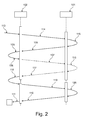
- Fig. 2 shows a schematic representation of the synchronization method according to the invention according to an embodiment of the present invention, wherein the connection structure in the embodiment shown here, starting from the server.
- the server 102 After a previous event 113 (eg, after an interaction of the WEB-VV user), the server 102 starts a clock comparison request 114 to the field device 101.
- the field device 101 responds with the current time value generation 115 current time comparison data.
- the field device 101 sends 104 the current time value or the time comparison data to the server.
- the server in turn compares 105 the current time value with the setpoint. Depending on the result of the comparison, that is, depending on whether this time difference is greater or less than a predefined threshold value, a request for time synchronization 106 takes place.
- the server 102 sends the current server time "Server Date Time” together with the "status" setDeviceTime and thus requests the field device for time synchronization.
- the field device 101 in turn reacts with a correction 116 of the device time and the trend data.
- the field device 101 sends an acknowledgment 117 to the server via the data and communication network, so far as everything is in order, e.g. For example, enter an http status 200 and confirm the correction of the device time and the trend data.
- the event "time synchronization in the field device” is stored in the message buffer in the server 102 118. This is followed by sending a request 119 for data exchange.
- the field device 101 is thus requested to generate measured value data 120, whereupon the field device 101 causes the data exchange 110 to the server 102.
- the data is sent via the data and communication network and taken over by the server 102 111.
- Fig. 3 shows a schematic measuring system according to an embodiment of the present invention, with a server 102, which contains a storage medium 130 and a CPU, so a microprocessor 131.
- the communication and data network 123 on which the method according to the invention is based is shown, and two globally distributed field devices 121 and 122 are shown by way of example. Via the communication and data network 123, it is therefore possible by the method according to the invention to realize the secure automated synchronization of the time base of these globally distributed controllers 121 and 122 in the process automation by means of a special time server 102.
- the controllers or field devices or even clients and the server can use the Internet as an exemplary embodiment of the data and communication network 123.
- Fig. 4 shows by way of example the surface of an operating software of the server for setting the device network access data for a field device of the method according to the invention. It can be clearly seen that the respective time zone in which the respective field device is located is shown here. However, it is important that the time zone is set and controlled centrally by the server according to the invention and controlled by the server. Thus, a high level of security can be ensured with respect to the synchronicity of all field devices with the server and the correct time zone setting in all external field devices. Should a user change the time zone, it will be detected by the server during the next communication over the communication and data network and will be corrected during the same communication and reset to the original correct time zone value. If such a synchronization has to take place, then this is archived in a message buffer on the server.
- Fig. 5 schematically shows an inventive measuring system 132 with a server 102 and a field device or a field device control 121. It can be clearly seen that both sides of the measuring system according to the invention the contact to the opposite side can be recorded, which is represented by the arrows starting from the respective initiator. This is done via the communication and data network 123.
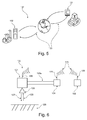
- Fig. 6 schematically shows a representation of the measuring system 132 according to the invention, which has a field device 101 and a connection 123a, for example in the form of a 4... 20 mA conductor loop for field device control 124.
- the server 102 like the field device controller and the field device, has an antenna 126.
- This antenna exemplifies the connection to the communication and data network 123.
- a wired connection may also exist.
- the field device 121 has a further second antenna 126 mounted in this image below, which in this case is aligned for measuring the fill level or the pressure.
- a transmission signal 127 and a reception signal 128 which checks the level of the contents 129.
- Fig.7 and Fig.8 show schematic representations of dialogs of the field device operating software.
- Fig. 7 represents the part in which the notification type is defined.
- Fig. 8 on the other hand, you can see the part that defines the sending time for sending messages. It can be seen that the interval of a query is displayed, which according to the invention can be set secured on the server side.
- the method according to an embodiment of the present invention forces the server owner to set the time zone for each participating client, which is central and server-side only. If the time base of a local client is accidentally changed, the server will register this on the next communication with the client and the client's time base will automatically be reset to the setpoint.
- the arrangement according to the invention can be used, for example, in the web-based measured value acquisition and visualization system "WEB-VV".
- WEB-VV web-based measured value acquisition and visualization system
- the server for example, WEB-VV receives its measured value information with associated time stamps from a variety of signal conditioning devices (clients) by file.
- this can be an XML file.
- the server also stores this information centrally in a database.
- the stored data can be combined as desired in the WEB-VV server and visualized via browser access as so-called measured value views, or passed on to higher-level tools, for example logistics tools, for further processing.
- the signal conditioning instruments can also provide history data with a timestamp as a file, for example in the form of XML data.
- FIG. 3 schematically shows a WEB-VV system.
- the server communicates with the signal conditioning instruments via four different services, whereby in the first variant the communication originates from the signal conditioning instrument.
- the service "Send measured value" is therefore initiated by the signal conditioning instrument.
- the services Scan Device Network, Update Measurement, and Set WEB VV Event Interval are initiated by the server.
- an http communication can be used, which allows both sides to obtain time information from the other party and to use it accordingly. Since the signal conditioning instruments can be located in any time zone, WEB-VV must be notified manually once when creating a device network. This is done by a prepared configuration dialog in the WEB-VV (see Fig. 4 ).
- WEB-VV is thus enabled to return its current time corrected to the local time of the signal conditioning instruments (see Fig. 5 ).
- both the signal conditioning devices and the WEB VV servers transmit their time information to the respective counterpart during each connection except for the "Scan Device Network” service.
- the decision as to whether a time synchronization should be made in the signal conditioning instrument lies solely with the server, in this case WEB-VV. This requests the signal conditioning instrument to synchronize if necessary.
- WEB-VV checks the device time information of incoming data, so for example from XML measured value data and compares this with the current computer time, ie the time of the server.
- the signal conditioning instruments store time stamp information in the structure ⁇ Values> in the measured value data, in this case in the XML measured value data.
- This time stamp information represents the time at which a measured value was recorded in the signal conditioning instrument and stored in the buffer.
- the signal conditioning instruments provide time information in the structure ⁇ Device>. This time information provides the current time in the signal conditioning instrument at the time of the data exchange with the server, ie with WEB-VV.
- the XML element Device can be sent in certain cases for the purpose of pure time synchronization without the measured value information.
- the content of the XML file is called XML time comparison data.
- WEB-VV converts both time information to UTC (Universal Time Coordinated). The conversion is done for the computer time based on the Windows country settings, for the device time "Time" of the signal conditioning instrument based on the time zone assignment of the device network in the server.
- WEB-VV generally takes the measured values together with the timestamps transmitted in the XML file into the database, whereby these are stored standardized according to UTC.
- the server After the server has completely accepted the data, it returns together with the http status the server time corrected to the local time zone of the signal conditioning instrument in its response.
- WEB-VV is exemplary for a server which is able to carry out the inventive implementation of a method for the automatic time synchronization of devices in network-based systems.
- the basic prerequisite for the interaction of signal conditioning instruments with WEB-VV is the activation of the WEB-VV function within a signal conditioning instrument.
- the function for communication with the system or the server software is thus set here in the signal conditioning instrument.
- FIGS. 7 and 8 shown dialogues of the signal conditioning control software, preferably presented by a Device Type Manager according to the specification of FDT.
- the signal conditioning instrument would automatically send measured value files to the server WEB-VV every hour between 8 am and 6 pm local time. It can clearly be seen that the frequency of the synchronization can be set here.
- a parameter for defining the permitted time deviation of the signal conditioning instruments is provided. For example, the default value of two minutes is entered and can be changed. If the actual deviation is within the limit value, the server, ie WEB-VV, returns the current server time "Server Date Time” together with the status: “Device Time OK”. Otherwise, the response will include the current server time "Server Date Time” along with the status "Set Device Time”.
- the process "Time synchronization in the signal conditioning instrument" is entered in the message buffer "Messages / Events" of the supervisor, ie on a part of the server.
- the signal conditioning instrument now performs a time synchronization.
- the actual data exchange is initiated with a command, ie the transfer of the complete data, for example the complete XML measured value data, to the server, thus for example with post 2 "... / DataExchange.aspx".
- the server takes the measured value data into the database and confirms the file receive with the HTTP status 200, whereby the XML response is omitted in this case. This ends the synchronization, in which the connection is initiated by the signal conditioning instrument.
- the following is an example of a synchronization in which the connection is initiated from the server.
- the signal conditioning instrument generates the time comparison data or the current time value or the XML time comparison data and returns them to WEB-VV, where the deviation between device time and server time is checked.
- the measured value data generated by the signal conditioning instrument are transferred to the database after arrival in the WEB-VV server.
- WEB-VV requests the signal conditioning instrument for time synchronization with a command with the content of the current server time "Server Date Time” together with the "status” "Set Device Time”.
- the process "Time synchronization in the signal conditioning instrument” is entered in the message buffer "Messages / Events" of the supervisor. After the time synchronization, the actual measured value data are then requested and transmitted as above.
- the synchronization example for a communication initiated by the WEB VV server ends.
- Additional mechanisms of the client regarding the system time of the client are implemented as an additional security measure to ensure the same time base.
- the system time of the clients (signal conditioning devices), which are integrated in the server network, is managed centrally via the server. Accordingly, the system time on site can no longer be influenced.
- the following software feature is implemented. Changing the system time is blocked if a WEB-VV event has been created and activated for the device.
- WEB VV event means the general setting within the field device or within the field device control for network-based time synchronization by an external server.
- the lock applies for key operation on the operating unit of the signal conditioning instrument as well as for operation via the operating software (eg so-called Device Type Manager, DTM).
- the evaluation device gives a message to the device's own Display when the user tries to edit the active lock with regard to time and date. If the time synchronization in a processor is triggered by a WEB-VV command or a WEB-VV response, the time stamps for the complete current recording and the real-time clock are corrected.
- Table 1 evaluation WEB-VV Response Reaction in the evaluation unit Watch comparison at Http status eg 200 Correct real-time clock and "Send measured values" with: 7-8 * .GND timestamp ⁇ IP> /Web-W/InBox/TimeExchange.aspx ⁇ Response> correct ⁇ ServerDateTime> 2005-10-18 10:20:12 ⁇ / Server datetime> ⁇ Status> setDeviceTime ⁇ / State> ⁇ / Response>
- Table 2 with exemplary relevant commands using the example WEB-VV is shown.
- No time correction type scan network http: // ⁇ IP> /webvv/webvv.xml?
- No time correction type data exchange http: // ⁇ IP> /cgi/webvv/webvv.xml?
Landscapes
- Engineering & Computer Science (AREA)
- Physics & Mathematics (AREA)
- General Physics & Mathematics (AREA)
- Theoretical Computer Science (AREA)
- Automation & Control Theory (AREA)
- General Engineering & Computer Science (AREA)
- Computer And Data Communications (AREA)
- Synchronisation In Digital Transmission Systems (AREA)
- Electric Clocks (AREA)
Applications Claiming Priority (1)
| Application Number | Priority Date | Filing Date | Title |
|---|---|---|---|
| US97532007P | 2007-09-26 | 2007-09-26 |
Publications (3)
| Publication Number | Publication Date |
|---|---|
| EP2042957A2 true EP2042957A2 (fr) | 2009-04-01 |
| EP2042957A3 EP2042957A3 (fr) | 2014-07-02 |
| EP2042957B1 EP2042957B1 (fr) | 2018-08-01 |
Family
ID=40010955
Family Applications (1)
| Application Number | Title | Priority Date | Filing Date |
|---|---|---|---|
| EP08164067.4A Not-in-force EP2042957B1 (fr) | 2007-09-26 | 2008-09-10 | Système pour la synchronisation automatique des dispositifs dans un réseau |
Country Status (3)
| Country | Link |
|---|---|
| US (1) | US8838776B2 (fr) |
| EP (1) | EP2042957B1 (fr) |
| CN (1) | CN101399657A (fr) |
Cited By (3)
| Publication number | Priority date | Publication date | Assignee | Title |
|---|---|---|---|---|
| CN102364982A (zh) * | 2011-11-29 | 2012-02-29 | 电信科学技术研究院 | 一种混合自组网络中群间同步方法及终端 |
| DE102017120032A1 (de) * | 2017-08-31 | 2019-02-28 | Vega Grieshaber Kg | Verfahren zur zeitsynchronisierten Verarbeitung von Daten eines Feldgerätes der Prozessautomatisierung |
| US12073254B2 (en) | 2020-02-20 | 2024-08-27 | Analog Devices International Unlimited Company | Real time sense and control using embedded instruction timing |
Families Citing this family (21)
| Publication number | Priority date | Publication date | Assignee | Title |
|---|---|---|---|---|
| KR101303672B1 (ko) | 2007-10-15 | 2013-09-16 | 삼성전자주식회사 | 디바이스 및 디바이스 간의 컨텐츠 공유 방법 |
| JP5505771B2 (ja) * | 2009-10-09 | 2014-05-28 | コニカミノルタ株式会社 | 管理システム及び被管理装置並びに管理方法 |
| DE102010024210B4 (de) * | 2010-06-17 | 2012-09-20 | Abb Technology Ag | Feldgerät mit Echtzeituhr |
| JP5713340B2 (ja) * | 2010-12-21 | 2015-05-07 | インターナショナル・ビジネス・マシーンズ・コーポレーションInternational Business Machines Corporation | イベントの通知を送信する方法、並びにそのコンピュータ及びコンピュータ・プログラム |
| US9106645B1 (en) * | 2011-01-26 | 2015-08-11 | Symantec Corporation | Automatic reset for time-based credentials on a mobile device |
| CN102231656B (zh) * | 2011-06-20 | 2016-09-14 | 南京中兴新软件有限责任公司 | Ntp服务器时钟同步保持方法、系统及装置 |
| US8533153B2 (en) * | 2011-07-14 | 2013-09-10 | General Electric Company | Storing data following a power outage and without a proper time source |
| FR2982973B1 (fr) * | 2011-11-21 | 2014-05-23 | Bull Sas | Procedes de surveillance de grandeurs de dispositifs informatiques, programme d'ordinateur et dispositif associes |
| CN103514298A (zh) * | 2013-10-16 | 2014-01-15 | 浪潮(北京)电子信息产业有限公司 | 一种实现文件锁的方法及元数据服务器 |
| CN104639796B (zh) * | 2013-11-08 | 2017-11-21 | 浙江大华技术股份有限公司 | 一种监控服务器及其控制视频源设备时间同步的方法 |
| CN103873567B (zh) * | 2014-03-03 | 2018-09-04 | 北京智谷睿拓技术服务有限公司 | 基于任务的数据传输方法及数据传输装置 |
| CN105141458B (zh) * | 2015-08-25 | 2018-09-11 | 广州酷狗计算机科技有限公司 | 剩余时长展示方法和装置 |
| CN106094766A (zh) * | 2016-08-09 | 2016-11-09 | 红塔烟草(集团)有限责任公司 | 卷烟制丝生产线PLC时钟同步器与西门子Wincc工控PLC时钟同步器 |
| CN106361322A (zh) * | 2016-08-31 | 2017-02-01 | 博睿康科技(常州)股份有限公司 | 一种脑电装置的累计偏差自动检测方法和装置 |
| CN107874756A (zh) * | 2017-11-21 | 2018-04-06 | 博睿康科技(常州)股份有限公司 | 脑电采集系统和视频采集系统的精确同步方法 |
| CN110474702A (zh) * | 2018-05-10 | 2019-11-19 | 杭州涂鸦信息技术有限公司 | 一种基于System Clock,并且依赖服务端自动修复的时间服务的实现方法 |
| ES2882151T3 (es) * | 2018-07-20 | 2021-12-01 | Grieshaber Vega Kg | Aparato de campo alimentado por batería con transmisión de información de tiempo |
| CN109445517A (zh) * | 2018-11-08 | 2019-03-08 | 郑州云海信息技术有限公司 | 一种同步bmc和os时间的方法、装置、终端及存储介质 |
| CN111208866B (zh) * | 2019-12-27 | 2022-10-28 | 视联动力信息技术股份有限公司 | 一种系统时间调整方法和装置 |
| DE102020109537A1 (de) * | 2020-04-06 | 2021-10-07 | Krohne Messtechnik Gmbh | Verfahren zur bezahlbasierten Ausführung einer durchzuführenden Funktion eines Feldgerätes, entsprechendes Feldgerät und Serviceeinheit |
| CN116185507A (zh) * | 2023-02-14 | 2023-05-30 | 武汉高德智感科技有限公司 | 设备时间的设置方法和设置系统 |
Family Cites Families (14)
| Publication number | Priority date | Publication date | Assignee | Title |
|---|---|---|---|---|
| DE29820820U1 (de) * | 1998-11-20 | 2000-02-10 | Siemens AG, 80333 München | Netzwerkteilnehmer |
| US7023816B2 (en) * | 2000-12-13 | 2006-04-04 | Safenet, Inc. | Method and system for time synchronization |
| EP1430627B1 (fr) * | 2001-09-26 | 2005-02-09 | Siemens Aktiengesellschaft | Procede pour la synchronisation de noeuds d'un systeme de communication |
| US7352715B2 (en) * | 2001-11-30 | 2008-04-01 | Cellnet Innovations, Inc. | Time synchronization using dynamic thresholds |
| US6714160B2 (en) * | 2002-02-19 | 2004-03-30 | Eride, Inc. | Real time clock for GPS receivers |
| US7228417B2 (en) * | 2002-02-26 | 2007-06-05 | America Online, Inc. | Simple secure login with multiple-authentication providers |
| WO2004034883A2 (fr) * | 2002-10-15 | 2004-04-29 | Medtronic Inc. | Synchronisation et etalonnage d'horloges pour dispositif medical et horloge etalonnee |
| US8930579B2 (en) * | 2004-09-13 | 2015-01-06 | Keysight Technologies, Inc. | System and method for synchronizing operations of a plurality of devices via messages over a communication network |
| DE102004050386B4 (de) * | 2004-10-15 | 2014-10-09 | Siemens Aktiengesellschaft | Verfahren zur Analyse eines technischen Prozesses |
| US7574500B2 (en) * | 2005-02-14 | 2009-08-11 | Reactivity, Inc. | Establishing a cache expiration time to be associated with newly generated output by determining module- specific cache expiration times for a plurality of processing modules |
| CN100421495C (zh) | 2005-06-27 | 2008-09-24 | 华为技术有限公司 | 在设备管理中同步操作时间的方法及终端设备 |
| US20080079596A1 (en) * | 2006-09-29 | 2008-04-03 | Rockwell Automation Technologies, Inc. | Buffering alarms |
| US7991876B2 (en) * | 2006-12-19 | 2011-08-02 | International Business Machines Corporation | Management of monitoring sessions between monitoring clients and monitoring target server |
| US8842971B2 (en) * | 2007-07-31 | 2014-09-23 | The Directv Group, Inc. | Methods and apparatus to present audio and video at non-native rates |
-
2008
- 2008-08-19 US US12/194,057 patent/US8838776B2/en active Active
- 2008-09-10 EP EP08164067.4A patent/EP2042957B1/fr not_active Not-in-force
- 2008-09-24 CN CNA200810161289XA patent/CN101399657A/zh active Pending
Cited By (5)
| Publication number | Priority date | Publication date | Assignee | Title |
|---|---|---|---|---|
| CN102364982A (zh) * | 2011-11-29 | 2012-02-29 | 电信科学技术研究院 | 一种混合自组网络中群间同步方法及终端 |
| DE102017120032A1 (de) * | 2017-08-31 | 2019-02-28 | Vega Grieshaber Kg | Verfahren zur zeitsynchronisierten Verarbeitung von Daten eines Feldgerätes der Prozessautomatisierung |
| US11139947B2 (en) | 2017-08-31 | 2021-10-05 | Vega Grieshaber Kg | Method for the time-synchronized processing of data of a field device of process automation |
| DE102017120032B4 (de) * | 2017-08-31 | 2025-10-09 | Vega Grieshaber Kg | Verfahren zur zeitsynchronisierten Verarbeitung von Daten eines Feldgerätes der Prozessautomatisierung |
| US12073254B2 (en) | 2020-02-20 | 2024-08-27 | Analog Devices International Unlimited Company | Real time sense and control using embedded instruction timing |
Also Published As
| Publication number | Publication date |
|---|---|
| EP2042957A3 (fr) | 2014-07-02 |
| US8838776B2 (en) | 2014-09-16 |
| EP2042957B1 (fr) | 2018-08-01 |
| US20090083444A1 (en) | 2009-03-26 |
| CN101399657A (zh) | 2009-04-01 |
Similar Documents
| Publication | Publication Date | Title |
|---|---|---|
| EP2042957B1 (fr) | Système pour la synchronisation automatique des dispositifs dans un réseau | |
| EP3610605B1 (fr) | Procédé et dispositif de production d'une estampille temporelle cryptographique pour un document numérique sur une base majoritaire | |
| DE69032468T2 (de) | Uhrensynchronisation in einem rechnersystem | |
| DE102015206291B4 (de) | Zeitsynchronisierungsverfahren und -system für Fahrzeug AVB | |
| DE112011104944T5 (de) | Langzeit-Signaturendgerät, Langzeit-Signaturserver, Langzeit-Signatur-Endgeräteprogramm und Langzeit-Signaturserverprogramm | |
| EP4343467A2 (fr) | Dispositif d'automatisation en temps réel comprenant un bus de données en temps réel et un module logiciel d'interface | |
| WO2007098775A1 (fr) | Procedes et dspositifs pour la transmission d'informations d'heures d'envoi ou de reception d'un message envoyé ou recu | |
| EP3825880B1 (fr) | Remise à zéro protégée d'un appareil ido | |
| DE102020122781A1 (de) | Verfahren zur Übertragung von Daten von einem medizinischen Gerät sowie medizinisches Gerät | |
| EP3637205A1 (fr) | Déclenchement de l'image sur une station client de l'opérateur | |
| DE102013227141A1 (de) | Transfer einer Benutzerschnittstelle | |
| DE102005024340A1 (de) | Steuereinrichtungsmanagementsystem | |
| DE102017120032B4 (de) | Verfahren zur zeitsynchronisierten Verarbeitung von Daten eines Feldgerätes der Prozessautomatisierung | |
| EP1673915A2 (fr) | Procede pour faire fonctionner un serveur et objets correspondants | |
| DE10242918A1 (de) | System und Verfahren zum Aktualisieren von Informationen | |
| EP1307989B1 (fr) | Procede de communication | |
| EP3106950B1 (fr) | Systeme d'outil pour une installation de montage et procede pour un systeme d'outil pour une installation de montage | |
| EP3851923B1 (fr) | Système de guidage pour installations technique pourvu de gestion de certificats | |
| WO2005104055A2 (fr) | Procede et systeme pour la telesurveillance, la telecommande et/ou le telediagnostic d'un appareil | |
| DE102024105386B3 (de) | Smart Meter Gateway mit nachträglich aktivierbarer Netzwerkmanagement-Funktionalität und Verfahren zur nachträglichen Aktivierung einer Netzwerkmanagement-Funktionalität eines Smart Meter Gateways | |
| DE10150847B4 (de) | Einfache und sichere Methode zum Ermitteln der Zeitzone eines Internet Clients | |
| EP1316898A2 (fr) | Méthode simple et sûre pour verrouiller des ensembles de données à partir de scripts CGI | |
| DE10250581A1 (de) | Datensammlungsknoten, der HTTP-Übertragungsprotokolle für autonome Datenübertragungen verwendet | |
| DE102020211168B3 (de) | Verfahren und Vorrichtung zum Zustandsrücksetzen von Komponenten eines Fahrzeugs | |
| EP3748951B1 (fr) | Détermination d'un écart de temps d'une caméra d'un temps d'un registre d'horloge |
Legal Events
| Date | Code | Title | Description |
|---|---|---|---|
| PUAI | Public reference made under article 153(3) epc to a published international application that has entered the european phase |
Free format text: ORIGINAL CODE: 0009012 |
|
| AK | Designated contracting states |
Kind code of ref document: A2 Designated state(s): AT BE BG CH CY CZ DE DK EE ES FI FR GB GR HR HU IE IS IT LI LT LU LV MC MT NL NO PL PT RO SE SI SK TR |
|
| AX | Request for extension of the european patent |
Extension state: AL BA MK RS |
|
| PUAL | Search report despatched |
Free format text: ORIGINAL CODE: 0009013 |
|
| AK | Designated contracting states |
Kind code of ref document: A3 Designated state(s): AT BE BG CH CY CZ DE DK EE ES FI FR GB GR HR HU IE IS IT LI LT LU LV MC MT NL NO PL PT RO SE SI SK TR |
|
| AX | Request for extension of the european patent |
Extension state: AL BA MK RS |
|
| RIC1 | Information provided on ipc code assigned before grant |
Ipc: G06F 1/14 20060101ALI20140527BHEP Ipc: G05B 19/418 20060101AFI20140527BHEP Ipc: G05B 19/042 20060101ALI20140527BHEP |
|
| 17P | Request for examination filed |
Effective date: 20141219 |
|
| RBV | Designated contracting states (corrected) |
Designated state(s): AT BE BG CH CY CZ DE DK EE ES FI FR GB GR HR HU IE IS IT LI LT LU LV MC MT NL NO PL PT RO SE SI SK TR |
|
| AKX | Designation fees paid |
Designated state(s): AT BE BG CH CY CZ DE DK EE ES FI FR GB GR HR HU IE IS IT LI LT LU LV MC MT NL NO PL PT RO SE SI SK TR |
|
| AXX | Extension fees paid |
Extension state: RS Extension state: AL Extension state: BA Extension state: MK |
|
| 17Q | First examination report despatched |
Effective date: 20160726 |
|
| GRAP | Despatch of communication of intention to grant a patent |
Free format text: ORIGINAL CODE: EPIDOSNIGR1 |
|
| STAA | Information on the status of an ep patent application or granted ep patent |
Free format text: STATUS: GRANT OF PATENT IS INTENDED |
|
| INTG | Intention to grant announced |
Effective date: 20180316 |
|
| GRAS | Grant fee paid |
Free format text: ORIGINAL CODE: EPIDOSNIGR3 |
|
| GRAA | (expected) grant |
Free format text: ORIGINAL CODE: 0009210 |
|
| STAA | Information on the status of an ep patent application or granted ep patent |
Free format text: STATUS: THE PATENT HAS BEEN GRANTED |
|
| AK | Designated contracting states |
Kind code of ref document: B1 Designated state(s): AT BE BG CH CY CZ DE DK EE ES FI FR GB GR HR HU IE IS IT LI LT LU LV MC MT NL NO PL PT RO SE SI SK TR |
|
| REG | Reference to a national code |
Ref country code: GB Ref legal event code: FG4D Free format text: NOT ENGLISH |
|
| REG | Reference to a national code |
Ref country code: CH Ref legal event code: EP Ref country code: AT Ref legal event code: REF Ref document number: 1025025 Country of ref document: AT Kind code of ref document: T Effective date: 20180815 |
|
| REG | Reference to a national code |
Ref country code: IE Ref legal event code: FG4D Free format text: LANGUAGE OF EP DOCUMENT: GERMAN |
|
| REG | Reference to a national code |
Ref country code: DE Ref legal event code: R096 Ref document number: 502008016222 Country of ref document: DE |
|
| REG | Reference to a national code |
Ref country code: FR Ref legal event code: PLFP Year of fee payment: 11 |
|
| REG | Reference to a national code |
Ref country code: NL Ref legal event code: MP Effective date: 20180801 |
|
| REG | Reference to a national code |
Ref country code: LT Ref legal event code: MG4D |
|
| PG25 | Lapsed in a contracting state [announced via postgrant information from national office to epo] |
Ref country code: SE Free format text: LAPSE BECAUSE OF FAILURE TO SUBMIT A TRANSLATION OF THE DESCRIPTION OR TO PAY THE FEE WITHIN THE PRESCRIBED TIME-LIMIT Effective date: 20180801 Ref country code: BG Free format text: LAPSE BECAUSE OF FAILURE TO SUBMIT A TRANSLATION OF THE DESCRIPTION OR TO PAY THE FEE WITHIN THE PRESCRIBED TIME-LIMIT Effective date: 20181101 Ref country code: NO Free format text: LAPSE BECAUSE OF FAILURE TO SUBMIT A TRANSLATION OF THE DESCRIPTION OR TO PAY THE FEE WITHIN THE PRESCRIBED TIME-LIMIT Effective date: 20181101 Ref country code: GR Free format text: LAPSE BECAUSE OF FAILURE TO SUBMIT A TRANSLATION OF THE DESCRIPTION OR TO PAY THE FEE WITHIN THE PRESCRIBED TIME-LIMIT Effective date: 20181102 Ref country code: IS Free format text: LAPSE BECAUSE OF FAILURE TO SUBMIT A TRANSLATION OF THE DESCRIPTION OR TO PAY THE FEE WITHIN THE PRESCRIBED TIME-LIMIT Effective date: 20181201 Ref country code: PL Free format text: LAPSE BECAUSE OF FAILURE TO SUBMIT A TRANSLATION OF THE DESCRIPTION OR TO PAY THE FEE WITHIN THE PRESCRIBED TIME-LIMIT Effective date: 20180801 Ref country code: FI Free format text: LAPSE BECAUSE OF FAILURE TO SUBMIT A TRANSLATION OF THE DESCRIPTION OR TO PAY THE FEE WITHIN THE PRESCRIBED TIME-LIMIT Effective date: 20180801 Ref country code: LT Free format text: LAPSE BECAUSE OF FAILURE TO SUBMIT A TRANSLATION OF THE DESCRIPTION OR TO PAY THE FEE WITHIN THE PRESCRIBED TIME-LIMIT Effective date: 20180801 Ref country code: NL Free format text: LAPSE BECAUSE OF FAILURE TO SUBMIT A TRANSLATION OF THE DESCRIPTION OR TO PAY THE FEE WITHIN THE PRESCRIBED TIME-LIMIT Effective date: 20180801 |
|
| PG25 | Lapsed in a contracting state [announced via postgrant information from national office to epo] |
Ref country code: LV Free format text: LAPSE BECAUSE OF FAILURE TO SUBMIT A TRANSLATION OF THE DESCRIPTION OR TO PAY THE FEE WITHIN THE PRESCRIBED TIME-LIMIT Effective date: 20180801 Ref country code: ES Free format text: LAPSE BECAUSE OF FAILURE TO SUBMIT A TRANSLATION OF THE DESCRIPTION OR TO PAY THE FEE WITHIN THE PRESCRIBED TIME-LIMIT Effective date: 20180801 Ref country code: HR Free format text: LAPSE BECAUSE OF FAILURE TO SUBMIT A TRANSLATION OF THE DESCRIPTION OR TO PAY THE FEE WITHIN THE PRESCRIBED TIME-LIMIT Effective date: 20180801 |
|
| PG25 | Lapsed in a contracting state [announced via postgrant information from national office to epo] |
Ref country code: RO Free format text: LAPSE BECAUSE OF FAILURE TO SUBMIT A TRANSLATION OF THE DESCRIPTION OR TO PAY THE FEE WITHIN THE PRESCRIBED TIME-LIMIT Effective date: 20180801 Ref country code: EE Free format text: LAPSE BECAUSE OF FAILURE TO SUBMIT A TRANSLATION OF THE DESCRIPTION OR TO PAY THE FEE WITHIN THE PRESCRIBED TIME-LIMIT Effective date: 20180801 Ref country code: CZ Free format text: LAPSE BECAUSE OF FAILURE TO SUBMIT A TRANSLATION OF THE DESCRIPTION OR TO PAY THE FEE WITHIN THE PRESCRIBED TIME-LIMIT Effective date: 20180801 Ref country code: MC Free format text: LAPSE BECAUSE OF FAILURE TO SUBMIT A TRANSLATION OF THE DESCRIPTION OR TO PAY THE FEE WITHIN THE PRESCRIBED TIME-LIMIT Effective date: 20180801 Ref country code: IT Free format text: LAPSE BECAUSE OF FAILURE TO SUBMIT A TRANSLATION OF THE DESCRIPTION OR TO PAY THE FEE WITHIN THE PRESCRIBED TIME-LIMIT Effective date: 20180801 |
|
| REG | Reference to a national code |
Ref country code: CH Ref legal event code: PL |
|
| REG | Reference to a national code |
Ref country code: DE Ref legal event code: R097 Ref document number: 502008016222 Country of ref document: DE |
|
| PG25 | Lapsed in a contracting state [announced via postgrant information from national office to epo] |
Ref country code: SK Free format text: LAPSE BECAUSE OF FAILURE TO SUBMIT A TRANSLATION OF THE DESCRIPTION OR TO PAY THE FEE WITHIN THE PRESCRIBED TIME-LIMIT Effective date: 20180801 Ref country code: DK Free format text: LAPSE BECAUSE OF FAILURE TO SUBMIT A TRANSLATION OF THE DESCRIPTION OR TO PAY THE FEE WITHIN THE PRESCRIBED TIME-LIMIT Effective date: 20180801 |
|
| PLBE | No opposition filed within time limit |
Free format text: ORIGINAL CODE: 0009261 |
|
| STAA | Information on the status of an ep patent application or granted ep patent |
Free format text: STATUS: NO OPPOSITION FILED WITHIN TIME LIMIT |
|
| REG | Reference to a national code |
Ref country code: BE Ref legal event code: MM Effective date: 20180930 |
|
| REG | Reference to a national code |
Ref country code: IE Ref legal event code: MM4A |
|
| PG25 | Lapsed in a contracting state [announced via postgrant information from national office to epo] |
Ref country code: LU Free format text: LAPSE BECAUSE OF NON-PAYMENT OF DUE FEES Effective date: 20180910 |
|
| 26N | No opposition filed |
Effective date: 20190503 |
|
| PG25 | Lapsed in a contracting state [announced via postgrant information from national office to epo] |
Ref country code: IE Free format text: LAPSE BECAUSE OF NON-PAYMENT OF DUE FEES Effective date: 20180910 |
|
| PG25 | Lapsed in a contracting state [announced via postgrant information from national office to epo] |
Ref country code: LI Free format text: LAPSE BECAUSE OF NON-PAYMENT OF DUE FEES Effective date: 20180930 Ref country code: CH Free format text: LAPSE BECAUSE OF NON-PAYMENT OF DUE FEES Effective date: 20180930 Ref country code: SI Free format text: LAPSE BECAUSE OF FAILURE TO SUBMIT A TRANSLATION OF THE DESCRIPTION OR TO PAY THE FEE WITHIN THE PRESCRIBED TIME-LIMIT Effective date: 20180801 Ref country code: BE Free format text: LAPSE BECAUSE OF NON-PAYMENT OF DUE FEES Effective date: 20180930 |
|
| REG | Reference to a national code |
Ref country code: AT Ref legal event code: MM01 Ref document number: 1025025 Country of ref document: AT Kind code of ref document: T Effective date: 20180910 |
|
| PG25 | Lapsed in a contracting state [announced via postgrant information from national office to epo] |
Ref country code: MT Free format text: LAPSE BECAUSE OF FAILURE TO SUBMIT A TRANSLATION OF THE DESCRIPTION OR TO PAY THE FEE WITHIN THE PRESCRIBED TIME-LIMIT Effective date: 20180801 Ref country code: AT Free format text: LAPSE BECAUSE OF NON-PAYMENT OF DUE FEES Effective date: 20180910 |
|
| PG25 | Lapsed in a contracting state [announced via postgrant information from national office to epo] |
Ref country code: TR Free format text: LAPSE BECAUSE OF FAILURE TO SUBMIT A TRANSLATION OF THE DESCRIPTION OR TO PAY THE FEE WITHIN THE PRESCRIBED TIME-LIMIT Effective date: 20180801 |
|
| PG25 | Lapsed in a contracting state [announced via postgrant information from national office to epo] |
Ref country code: HU Free format text: LAPSE BECAUSE OF FAILURE TO SUBMIT A TRANSLATION OF THE DESCRIPTION OR TO PAY THE FEE WITHIN THE PRESCRIBED TIME-LIMIT; INVALID AB INITIO Effective date: 20080910 Ref country code: PT Free format text: LAPSE BECAUSE OF FAILURE TO SUBMIT A TRANSLATION OF THE DESCRIPTION OR TO PAY THE FEE WITHIN THE PRESCRIBED TIME-LIMIT Effective date: 20180801 |
|
| PG25 | Lapsed in a contracting state [announced via postgrant information from national office to epo] |
Ref country code: CY Free format text: LAPSE BECAUSE OF FAILURE TO SUBMIT A TRANSLATION OF THE DESCRIPTION OR TO PAY THE FEE WITHIN THE PRESCRIBED TIME-LIMIT Effective date: 20180801 |
|
| PGFP | Annual fee paid to national office [announced via postgrant information from national office to epo] |
Ref country code: GB Payment date: 20230921 Year of fee payment: 16 |
|
| PGFP | Annual fee paid to national office [announced via postgrant information from national office to epo] |
Ref country code: FR Payment date: 20230918 Year of fee payment: 16 Ref country code: DE Payment date: 20230919 Year of fee payment: 16 |
|
| P01 | Opt-out of the competence of the unified patent court (upc) registered |
Free format text: CASE NUMBER: UPC_APP_328145/2023 Effective date: 20230523 |
|
| REG | Reference to a national code |
Ref country code: DE Ref legal event code: R119 Ref document number: 502008016222 Country of ref document: DE |
|
| GBPC | Gb: european patent ceased through non-payment of renewal fee |
Effective date: 20240910 |
|
| PG25 | Lapsed in a contracting state [announced via postgrant information from national office to epo] |
Ref country code: DE Free format text: LAPSE BECAUSE OF NON-PAYMENT OF DUE FEES Effective date: 20250401 |
|
| PG25 | Lapsed in a contracting state [announced via postgrant information from national office to epo] |
Ref country code: GB Free format text: LAPSE BECAUSE OF NON-PAYMENT OF DUE FEES Effective date: 20240910 |
|
| PG25 | Lapsed in a contracting state [announced via postgrant information from national office to epo] |
Ref country code: FR Free format text: LAPSE BECAUSE OF NON-PAYMENT OF DUE FEES Effective date: 20240930 |