EP2043029A2 - Zur Kopplung von elektrischen Komponenten an einen Steckplatz in einer Hostvorrichtung konfigurierter Adapter - Google Patents
Zur Kopplung von elektrischen Komponenten an einen Steckplatz in einer Hostvorrichtung konfigurierter Adapter Download PDFInfo
- Publication number
- EP2043029A2 EP2043029A2 EP08253150A EP08253150A EP2043029A2 EP 2043029 A2 EP2043029 A2 EP 2043029A2 EP 08253150 A EP08253150 A EP 08253150A EP 08253150 A EP08253150 A EP 08253150A EP 2043029 A2 EP2043029 A2 EP 2043029A2
- Authority
- EP
- European Patent Office
- Prior art keywords
- electrical component
- expresscard
- sides
- millimeter
- adapter
- Prior art date
- Legal status (The legal status is an assumption and is not a legal conclusion. Google has not performed a legal analysis and makes no representation as to the accuracy of the status listed.)
- Withdrawn
Links
Images


Classifications
-
- G—PHYSICS
- G06—COMPUTING OR CALCULATING; COUNTING
- G06F—ELECTRIC DIGITAL DATA PROCESSING
- G06F1/00—Details not covered by groups G06F3/00 - G06F13/00 and G06F21/00
- G06F1/16—Constructional details or arrangements
-
- G—PHYSICS
- G06—COMPUTING OR CALCULATING; COUNTING
- G06K—GRAPHICAL DATA READING; PRESENTATION OF DATA; RECORD CARRIERS; HANDLING RECORD CARRIERS
- G06K19/00—Record carriers for use with machines and with at least a part designed to carry digital markings
- G06K19/06—Record carriers for use with machines and with at least a part designed to carry digital markings characterised by the kind of the digital marking, e.g. shape, nature, code
- G06K19/067—Record carriers with conductive marks, printed circuits or semiconductor circuit elements, e.g. credit or identity cards also with resonating or responding marks without active components
- G06K19/07—Record carriers with conductive marks, printed circuits or semiconductor circuit elements, e.g. credit or identity cards also with resonating or responding marks without active components with integrated circuit chips
- G06K19/077—Constructional details, e.g. mounting of circuits in the carrier
-
- G—PHYSICS
- G06—COMPUTING OR CALCULATING; COUNTING
- G06F—ELECTRIC DIGITAL DATA PROCESSING
- G06F1/00—Details not covered by groups G06F3/00 - G06F13/00 and G06F21/00
- G06F1/16—Constructional details or arrangements
- G06F1/1613—Constructional details or arrangements for portable computers
- G06F1/1633—Constructional details or arrangements of portable computers not specific to the type of enclosures covered by groups G06F1/1615 - G06F1/1626
- G06F1/1635—Details related to the integration of battery packs and other power supplies such as fuel cells or integrated AC adapter
-
- G—PHYSICS
- G06—COMPUTING OR CALCULATING; COUNTING
- G06F—ELECTRIC DIGITAL DATA PROCESSING
- G06F13/00—Interconnection of, or transfer of information or other signals between, memories, input/output devices or central processing units
-
- G—PHYSICS
- G06—COMPUTING OR CALCULATING; COUNTING
- G06F—ELECTRIC DIGITAL DATA PROCESSING
- G06F2212/00—Indexing scheme relating to accessing, addressing or allocation within memory systems or architectures
- G06F2212/30—Providing cache or TLB in specific location of a processing system
- G06F2212/303—In peripheral interface, e.g. I/O adapter or channel
Definitions
- This invention relates generally to adapters for electrical devices, and relates more particularly to adapters that couple electrical components to slots in host devices and methods of using the same.
- the ExpressCard standard provides a method and standard interface for creating a direct connection between an electrical component and a system bus in a computer.
- the ExpressCard standard provides for electrical components with two widths: 54 millimeter and 34 millimeters. Both the 34 millimeter ExpressCards and 54 millimeter ExpressCards use the same type of connector to couple to the system bus. That is, both the 34 millimeter and 54 millimeter ExpressCards each have 26-pin beam-on-blade connectors. Accordingly, 34 millimeter ExpressCards can be plugged into 54 millimeter ExpressCard slots.
- Couple should be broadly understood and refer to connecting two or more elements or signals, electrically and/or mechanically, either directly or indirectly through intervening circuitry and/or elements.
- Two or more electrical elements may be electrically coupled, either direct or indirectly, but not be mechanically coupled;
- two or more mechanical elements may be mechanically coupled, either direct or indirectly, but not be electrically coupled;
- two or more electrical elements may be mechanically coupled, directly or indirectly, but not be electrically coupled.
- Coupling (whether only mechanical, only electrical, or both) may be for any length of time, e.g., permanent or semi-permanent or only for an instant.
- Electrode coupling and the like should be broadly understood and include coupling involving any electrical signal, whether a power signal, a data signal, and/or other types or combinations of electrical signals.
- Mechanical coupling and the like should be broadly understood and include mechanical coupling of all types.
- an adapter is configured to couple an electrical component to a slot in a host device.
- the electrical component has at least three sides.
- the adapter includes: (a) a first housing piece configured to be coupled to two or more sides of the at least three sides of the electrical component when the adapter is coupled to the electrical component; and (b) a second housing piece coupled to the first housing piece and configured to couple to a first side of the at least three sides of the electrical component when the adaptor is coupled to the electrical component.
- a portion of the second housing piece can be configured to be located inside the slot in the host device along with the electrical component.
- the first housing piece can be located outside of the slot.
- the 34 millimeter ExpressCard has two or more sides, and a first side of the two or more sides of the 34 millimeter ExpressCard includes an attachment mechanism.
- the extender includes: (a) an insertion portion having a first attachment mechanism; and (b) a holding portion having at least two sides and coupled to the insertion portion.
- the insertion portion can be configured such that a part of the insertion portion is located in the 54 millimeter ExpressCard slot along with the 34 millimeter ExpressCard when the extender is coupled to the 34 millimeter ExpressCard.
- the first attachment mechanism of the insertion portion can be configured to couple to the attachment mechanism of the 34 millimeter ExpressCard.
- the holding portion can be configured to be external to the 54 millimeter ExpressCard slot when the extender is coupled to the 34 millimeter ExpressCard and when the at least the part of the insertion portion and the 34 millimeter ExpressCard are located in the 54 millimeter ExpressCard slot.
- a first side of the at least two sides of the holding portion can be configured to adjoin the first side of the two or more sides of the 34 millimeter ExpressCard when the extender is coupled to the 34 millimeter ExpressCard.
- a second side of the at least two sides of the holding portion can be configured to adjoin a second side of the two or more sides of the 34 millimeter ExpressCard when the extender is coupled to the 34 millimeter ExpressCard.
- Yet another embodiment discloses a method of coupling an electrical component to a slot in a host device.
- the electrical component has at least three sides.
- the method includes: (a) providing an adapter having: (1) a first housing piece; and (2) a second housing piece; (b) coupling the adapter to the electrical component such that the first housing piece is adjacent to two or more sides of the at least three sides of the electrical component and the second housing piece is adjacent to a first side of the at least three sides of the electrical component; and (c) inserting the electrical component and a portion of the second housing piece inside the slot in the host device while the first housing piece is exterior to the slot in the host device.
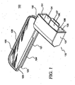
- FIG. 1 illustrates a top, left, front isometric view of an adapter 100, according to a first embodiment.
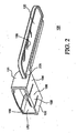
- FIG. 2 illustrates a bottom, right, front isometric view of adapter 100, according to the first embodiment.
- Adapter 100 is merely exemplary and is not limited to the embodiments presented herein. Adapter 100 can be employed in many different embodiments or examples not specifically depicted or described herein.
- an extender or adapter 100 can include: (a) a housing piece or an insertion portion 120; (b) a housing piece or holding portion 130 coupled to insertion portion 120. Insertion portion 120 is coupled to holding portion at a region 225 ( FIG. 2 ).
- adapter 100 has a unitary structure.
- holding portion 130 is configured to be detachable from insertion portion 120.
- holding portion 130 can be detachable from insertion portion 120 at region 225.
- a first portion of adapter 100 can be detached from a second portion of adapter 100 at a region other than region 225.
- Insertion portion 120 can include: (a) a body portion 126; and (b) an attachment mechanism 121.
- attachment mechanism 121 can include a groove 124 formed by ridges 122 and 123.
- body portion 126 is approximately 67.5 millimeters (mm) long and 20 mm wide.
- Holding portion 130 can include: (a) a side 131; (b) a side 132 adjacent to side 131; (c) a side 133 spaced apart from side 131 and adjacent to side 132; (d) a side 134 spaced apart from side 132 and adjacent to sides 131 and 132. Sides 131, 132, 133, and 134 form a channel 135. In one example, holding portion 130 has a height of approximately 12.3 mm and a width of approximately 34.2 mm.
- holding portion 130 can further include a coupling or attachment mechanism 136.
- attachment mechanism 136 can include a finger 139 at side 134 that can be depressed using a handle 137.
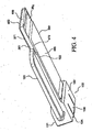
- FIG. 3 illustrates a top, right, front isometric view of adapter 100 coupled to an electrical component 350, according to the first embodiment.
- FIG. 4 illustrates a bottom, right, back isometric view of adapter 100 coupled to electrical component 350, according to the first embodiment.
- adapter 100 is configured and designed to couple to electrical component 350.
- electrical component 350 can include: (a) a side 361; (b) a side 462 ( FIG. 4 ) adjacent to side 361 and having a data connector 469 ( FIG. 4 ); (c) a side 363 adjacent to side 462 and opposite side 361; (d) a side 364 adjacent to sides 361, 462, and 363; (e) a side 465 ( FIG. 4 ) opposite side 364 and adjacent to sides 361, 462, and 363; and (f) a side 366 opposite side 462 and adjacent to sides 361, 363, 364, and 465.
- electrical component 350 can be considered to include a rear housing portion 367 and a front housing portion 368.
- electrical component 350 can further include one or more coupling or attachment mechanisms 370.
- attachment mechanisms 370 can include grooves or channels 371 and 472 ( FIG. 4 ). Channels 371 and 472 can be located at and protrude from sides 361 and 363, respectively.
- Holding portion 130 can be configured to couple to rear housing portion 367. That is, holding portion 130 can be configured to circumscribe or fit around at least a portion of electrical component 350. Holding portion 130 can be sized and shaped such that rear housing portion 367 can be placed inside of channel 135.
- holding portion 130 can be configured to be adjacent to four sides of electrical component 350 when adapter 100 is coupled to electrical component 350. That is, when adapter 100 is coupled to electrical component 350, holding portion 130 is configured such that: (a) side 131 is adjacent to side 361; (b) side 132 is adjacent to side 364; (c) side 133 is adjacent to side 363; and (d) side 134 is adjacent to side 465. In some embodiments, the size and the shape of holding portion 130 conforms to the size and shape of rear housing portion 367.
- insertion portion 120 is configured to couple at least to front housing portion 368. In some examples, insertion portion 120 can coupled to side 361 of electrical component 350.
- attachment mechanism 121 is configured to couple to the attachment mechanisms 370. That is, attachment mechanism 121 can be configured to couple to channel 371 and/or channel 472. For example, when adapter 100 is coupled to electrical component 350, ridges 122 and 123 can be located in and/or attach to channels 371 or 472 to help securely couple insertion portion 120 to side 361.
- attachment mechanism 136 can be configured to couple to side 465 of electrical component 350.
- attachment mechanism 136 can hold rear housing portion 367 or another portion of electrical component 350 in channel 135. A user can release electrical component 350 from adapter 100 by depressing handle 137.
- electrical component 350 can include other or additional attachments mechanisms.
- electrical component 350 could include a hook (not shown) capable of coupling to a snap (not shown) on adapter 100.
- FIG. 5 illustrates a right, top isometric view of adapter 100 and electrical component 350 coupled to a receiving component 586, according to the first embodiment.
- FIG. 6 illustrates a right, front, top isometric view of adapter 100 and electrical component 350 inside of a slot 685 in a host device 680.
- receiving component 586 can be a part of host device 680 ( FIG. 6 ) and located adjacent to and/or within slot 685 ( FIG. 6 ). In these embodiments, when electrical component 350 is inside of slot 685, electrical component 350 is also coupled to receiving component 586. Front housing portion 368 is capable of being placed into slot 685 while rear housing portion 367 is outside of slot 685. Data connector 469 ( FIG. 4 ) can be configured to couple to an electrical connector of receiving component 586.
- adapter 100 can be configured to couple to electrical component 350 and help securely couple electrical component 350 to receiving component 586.
- adapter 100 can be configured to help securely place electrical component 350 in slot 685 in host device 680.
- insertion portion 120 can be configured to be placed into slot 685 along with electrical component 350 when adapter 100 is coupled to electrical component 350.
- insertion portion 120 can be inserted into slot 685 if the slot is an L-shaped 54 millimeter ExpressCard slot. In some embodiments, only a part of insertion portion 120 is placed inside slot 685 with electrical component 350. In other embodiments, all of insertion portion 120 is placed inside of slot 685.
- Holding portion 130 can be configured to be substantially external to slot 685 when adapter 100 is coupled to electrical component 350 and electrical component 350 and at least a part of insertion portion 120 is placed into slot 685.
- adapter 100 securely couples to electrical component 350 while allowing unobstructed coupling of secondary electrical components, connectors, adapters, and cables to rear housing portion 367.
- electrical component is a 34 millimeter ExpressCard.
- electrical component 350 can be a 54 millimeter ExpressCard, a PCMCIA (Personal Computer Memory Card International Association) card, a CardBus card, a CompactFlash card, a MiniCard, a SmartMedia card, a MemoryStick card, or the like.
- PCMCIA Personal Computer Memory Card International Association
- Adapter 100 is preferably made of a material that is tough, hard, and rigid, has good chemical and heat resistance and dimensional stability, exhibits good creep resistance, and is relatively strong and inexpensive. Accordingly, adapter 100 can be constructed of acrylonitrile butadiene styrene (ABS), polycarbonate, polypropylene, polyethylene, or a similar material, all of which, to varying degrees, exhibit the stated properties.
- ABS acrylonitrile butadiene styrene
- adapter 100 is made using an injection molding process.
- holding portion 130 and insertion portion 120 can be made of different materials.
- insertion portion 120 can be made of a first plastic and holding portion 130 can be made of a second more flexible material (e.g. rubber, metal, or a different plastic).
- FIG. 7 illustrates a bottom, left, back isometric view of an adapter 700, according to a second embodiment.
- FIG. 8 illustrates a bottom, left, front isometric view of adapter 700 coupled to electrical component 350, according to the second embodiment.
- adapter 700 can include: (a) an insertion portion 720; (b) a holding portion 730 coupled to insertion portion 720. Similar to adapter 100 ( FIG. 1 ), adapter 700 can be configured to couple to electrical component 350 and help securely couple electrical component 350 to receiving component 586 ( FIG. 5 ) in host device 680 ( FIG. 6 ).
- holding portion 730 includes: (a) a side 731; and (b) a side 732 adjacent to side 731; and (c) a side 733 spaced apart from side 731 and adjacent to side 732.
- holding portion 730 is configured such that: (a) side 731 is adjacent to side 361; (b) side 732 is adjacent to side 465; and (c) side 733 is adjacent to side 363.
- insertion portion 720 can be configured to be placed into slot 685 ( FIG. 6 ) along with electrical component 350 when adapter 700 is coupled to electrical component 350.
- Holding portion 730 can be configured to be substantially external to slot 685 ( FIG. 6 ) when adapter 700 is coupled to electrical component 350 and when electrical component 350 and at least a part of insertion portion 720 are placed into slot 685 ( FIG. 6 ).
- FIG. 9 illustrates a top, right, front isometric view of an adapter 900. according to a third embodiment.
- FIG. 10 illustrates a top, left, front isometric view of adapter 900, according to the third embodiment.
- adapter 900 can include (a) an insertion portion 920; (b) a holding portion 930 coupled to insertion portion 920; and (c) coupling mechanisms 941, 1042, and 1043. Similar to adapters 100 and 700 ( FIGs. 1 and 7 , respectively), adapter 900 can be configured to couple to electrical component 350 ( FIG. 3 ) and help securely couple electrical component 350 to receiving component 586 ( FIG. 5 ) in host device 680 ( FIG. 6 ).
- Holding portion 730 can be configured to be adjacent to sides 361, 363, and 465 ( FIGs. 3 and 4 ) of electrical component 350 when adapter 700 is coupled to electrical component 350 ( FIG. 3 ).
- Coupling mechanisms 941, 1042, and 1043 can be used to hold adapter 900 to electrical component 350 ( FIG. 3 ).
- coupling mechanism 1042 can be similar to attachment mechanism 121.
- Coupling mechanisms 941 and 1043 can attach to complementary coupling mechanisms on the electrical component.
- coupling mechanisms 941 and 1043 can be snaps that attach to complementary snaps on electrical component 350 ( FIG. 3 ).
- Coupling mechanism 941 and 1043 can couple to opposite sides of electrical component 350 ( FIG. 3 ).
- At least a portion of insertion portion 920 can be configured to be placed into slot 685 ( FIG. 6 ) along with electrical component 350 ( FIG. 3 ) when adapter 900 is coupled to electrical component 350 ( FIG. 3 ).
- Holding portion 930 can be configured to be substantially external to slot 685 ( FIG. 6 ) when adapter 900 is coupled to electrical component 350 ( FIG. 3 ) and when electrical component 350 ( FIG. 3 ) and at least a part of insertion portion 920 are placed into slot 685 ( FIG. 6 ).
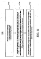
- FIG. 11 illustrates a flow chart 1100 for an embodiment of a method of coupling an electrical component to a slot in a host device.
- the electrical device can be identical or similar to electrical component 350 of FIGs. 3 and 8 .
- the host device can be identical or similar to host device 680 of FIG. 6 .
- the slot can be identical or similar to slot 685 of FIG. 6 .
- Flow chart 1100 includes a step 1110 of providing an adapter including: (a) a first housing section; and (b) a second housing section.
- the adapter can be similar or identical to adapters 100, 700, or 900 of FIGs. 1 , 7 , and 9 , respectively.
- the first housing section can be identical or similar to holding portions 130, 730, or 930 of FIGs. 1 , 7 , and 9 , respectively.
- the second housing section can be similar or identical to insertion portions 120, 720, or 920 of FIGs. 1 , 7 , and 9 , respectively.
- Flow chart 1100 in FIG. 11 continues with a step 1120 of coupling the adapter to the electrical component such that the first housing section is adjacent to two or more sides of the at least three sides of the electrical component and the second housing section is adjacent to a first side of the at least three sides of the electrical component.
- the adapter can be coupled to the electrical component similar or identical to the coupling of adapters 100 and 700 and electrical component 350 as shown in FIGs. 3 and 8 , respectively, and as described with reference to FIGs. 9 and 10 .
- the first side of the at least three sides of the electrical component is one of the two or more sides of the at least three sides of the electrical component. In alternative embodiments, the first side of the at least three sides of the electrical component is different from the two or more sides of the at least three sides of the electrical component.
- flow chart 1100 in FIG. 11 includes a step 1130 of inserting the electrical component and a portion of the second housing section inside the slot in the host while the first housing section is exterior to the slot in the host device.
- the insertion of the electrical component and the adapter inside the slot can be similar or identical to electrical component 350 and adapter 100 inserted into the host device 680 as shown in FIG. 6 , among other embodiments disclosed herein.
- embodiments and limitations disclosed herein are not dedicated to the public under the doctrine of dedication if the embodiments and/or limitations: (1) are not expressly claimed in the claims; and (2) are or are potentially equivalents of express elements and/or limitations in the claims under the doctrine of equivalents.
Landscapes
- Engineering & Computer Science (AREA)
- Theoretical Computer Science (AREA)
- Physics & Mathematics (AREA)
- General Physics & Mathematics (AREA)
- Computer Hardware Design (AREA)
- Microelectronics & Electronic Packaging (AREA)
- General Engineering & Computer Science (AREA)
- Human Computer Interaction (AREA)
- Power Engineering (AREA)
- Details Of Connecting Devices For Male And Female Coupling (AREA)
- Connector Housings Or Holding Contact Members (AREA)
- Casings For Electric Apparatus (AREA)
Applications Claiming Priority (1)
| Application Number | Priority Date | Filing Date | Title |
|---|---|---|---|
| US11/904,759 US7715181B2 (en) | 2007-09-28 | 2007-09-28 | Adapter configured to couple electrical component to slot in host device |
Publications (2)
| Publication Number | Publication Date |
|---|---|
| EP2043029A2 true EP2043029A2 (de) | 2009-04-01 |
| EP2043029A3 EP2043029A3 (de) | 2009-12-02 |
Family
ID=40210752
Family Applications (1)
| Application Number | Title | Priority Date | Filing Date |
|---|---|---|---|
| EP08253150A Withdrawn EP2043029A3 (de) | 2007-09-28 | 2008-09-26 | Zur Kopplung von elektrischen Komponenten an einen Steckplatz in einer Hostvorrichtung konfigurierter Adapter |
Country Status (7)
| Country | Link |
|---|---|
| US (1) | US7715181B2 (de) |
| EP (1) | EP2043029A3 (de) |
| JP (1) | JP2009110941A (de) |
| KR (1) | KR20090033154A (de) |
| CN (1) | CN101483292A (de) |
| MX (1) | MX2008012425A (de) |
| TW (1) | TW200933346A (de) |
Families Citing this family (1)
| Publication number | Priority date | Publication date | Assignee | Title |
|---|---|---|---|---|
| TWI334083B (en) * | 2007-06-27 | 2010-12-01 | Avermedia Tech Inc | Television card with remote control module |
Family Cites Families (12)
| Publication number | Priority date | Publication date | Assignee | Title |
|---|---|---|---|---|
| DE19710515C1 (de) | 1997-03-13 | 1998-08-20 | Itt Mfg Enterprises Inc | Steckkarte für elektronische Geräte |
| USD450708S1 (en) | 2000-07-20 | 2001-11-20 | Hon Hai Precision Ind. Co., Ltd. | Electronic card device |
| USD478087S1 (en) | 2002-07-02 | 2003-08-05 | Contour Electronics Limited | Memory card and connector |
| USD491191S1 (en) | 2003-04-14 | 2004-06-08 | C-One Technology Corporation | Adapter for removable electronic card |
| USD533505S1 (en) | 2004-02-13 | 2006-12-12 | George Chen | Multi-function converter connector |
| US7059913B1 (en) | 2005-05-31 | 2006-06-13 | D & C Technology Co., Ltd. | Express card adapter card |
| US7558898B2 (en) | 2006-08-30 | 2009-07-07 | ACCO Brands Corporation | Port replicating apparatus |
| TWM308538U (en) | 2006-09-29 | 2007-03-21 | Tai Sol Electronics Co Ltd | Card connector with small-card guiding function |
| USD576626S1 (en) | 2007-05-30 | 2008-09-09 | Kyocera Wireless Corp. | Wireless communication device PC card |
| USD580442S1 (en) | 2007-06-08 | 2008-11-11 | Samsung Electronics Co., Ltd. | Lan card for wireless data communication |
| US7780477B2 (en) | 2007-06-29 | 2010-08-24 | Sandisk Corporation | Adapter system for use with an expresscard slot |
| US7699660B2 (en) * | 2007-06-29 | 2010-04-20 | Sandisk Corporation | Adapter for an expresscard slot |
-
2007
- 2007-09-28 US US11/904,759 patent/US7715181B2/en not_active Expired - Fee Related
-
2008
- 2008-09-26 EP EP08253150A patent/EP2043029A3/de not_active Withdrawn
- 2008-09-26 TW TW097137179A patent/TW200933346A/zh unknown
- 2008-09-26 MX MX2008012425A patent/MX2008012425A/es active IP Right Grant
- 2008-09-26 JP JP2008248270A patent/JP2009110941A/ja active Pending
- 2008-09-28 CN CN200810189576.1A patent/CN101483292A/zh active Pending
- 2008-09-29 KR KR1020080095489A patent/KR20090033154A/ko not_active Withdrawn
Non-Patent Citations (1)
| Title |
|---|
| None |
Also Published As
| Publication number | Publication date |
|---|---|
| US7715181B2 (en) | 2010-05-11 |
| CN101483292A (zh) | 2009-07-15 |
| KR20090033154A (ko) | 2009-04-01 |
| US20090088004A1 (en) | 2009-04-02 |
| JP2009110941A (ja) | 2009-05-21 |
| MX2008012425A (es) | 2009-04-15 |
| EP2043029A3 (de) | 2009-12-02 |
| TW200933346A (en) | 2009-08-01 |
Similar Documents
| Publication | Publication Date | Title |
|---|---|---|
| AU2006261906B2 (en) | Multi-standard connection hub and method of manufacturing same | |
| CN102893463B (zh) | 便携式通用串行总线(usb)电缆组件 | |
| US6413108B2 (en) | Personal computer peripheral device adapter | |
| JP3253918B2 (ja) | 標準プラグを受入れるための統合レセプタクルを備えた着脱可能i/oデバイス | |
| US20080204992A1 (en) | Data storage system including recessed USB port | |
| EP2256886A2 (de) | Tischintegrierter USB Hub und Anschlusssystem | |
| EP1916591A1 (de) | Kabelverwaltungsvorrichtung und Verfahren zur Kabelverwaltung | |
| US20100130026A1 (en) | Electric plug and method of providing the same | |
| WO2010111045A1 (en) | Plug retention device | |
| WO2017054281A1 (zh) | 卡座结构及电子设备 | |
| US20090004921A1 (en) | Adapter system for use with an expresscard slot | |
| US20080038960A1 (en) | Micro sd adapter structure | |
| US7364439B2 (en) | Memory card assembly | |
| US7361050B2 (en) | Cable management device for use in connection with a power center, and cable management system comprising same | |
| US7715181B2 (en) | Adapter configured to couple electrical component to slot in host device | |
| US8657622B1 (en) | Electrical connector assembly | |
| US7359190B2 (en) | Interface for expansion module and expansion module bay | |
| CN219778145U (zh) | 用于移动设备的连接器组件 | |
| CN104951419B (zh) | 双总线快速卡外围设备 | |
| US8029306B2 (en) | Plug module | |
| CN201562204U (zh) | 具有可滑动连接端口的笔记本计算机 | |
| CN216413362U (zh) | 可拆卸式插排 | |
| CN210627079U (zh) | 扩展坞和移动终端 | |
| CN213093413U (zh) | 卡托及电子设备 | |
| TWI425338B (zh) | Usb接口保護蓋 |
Legal Events
| Date | Code | Title | Description |
|---|---|---|---|
| PUAI | Public reference made under article 153(3) epc to a published international application that has entered the european phase |
Free format text: ORIGINAL CODE: 0009012 |
|
| AK | Designated contracting states |
Kind code of ref document: A2 Designated state(s): AT BE BG CH CY CZ DE DK EE ES FI FR GB GR HR HU IE IS IT LI LT LU LV MC MT NL NO PL PT RO SE SI SK TR |
|
| AX | Request for extension of the european patent |
Extension state: AL BA MK RS |
|
| PUAL | Search report despatched |
Free format text: ORIGINAL CODE: 0009013 |
|
| AK | Designated contracting states |
Kind code of ref document: A3 Designated state(s): AT BE BG CH CY CZ DE DK EE ES FI FR GB GR HR HU IE IS IT LI LT LU LV MC MT NL NO PL PT RO SE SI SK TR |
|
| AX | Request for extension of the european patent |
Extension state: AL BA MK RS |
|
| 17P | Request for examination filed |
Effective date: 20100507 |
|
| 17Q | First examination report despatched |
Effective date: 20100604 |
|
| AKX | Designation fees paid |
Designated state(s): AT BE BG CH CY CZ DE DK EE ES FI FR GB GR HR HU IE IS IT LI LT LU LV MC MT NL NO PL PT RO SE SI SK TR |
|
| RAP1 | Party data changed (applicant data changed or rights of an application transferred) |
Owner name: BELKIN INTERNATIONAL, INC. |
|
| GRAP | Despatch of communication of intention to grant a patent |
Free format text: ORIGINAL CODE: EPIDOSNIGR1 |
|
| STAA | Information on the status of an ep patent application or granted ep patent |
Free format text: STATUS: THE APPLICATION IS DEEMED TO BE WITHDRAWN |
|
| 18D | Application deemed to be withdrawn |
Effective date: 20110708 |