EP2043171A2 - Module de piézoactionneur comprenant plusieurs piézoactionneurs reliés ensembles et son procédé de fabrication - Google Patents
Module de piézoactionneur comprenant plusieurs piézoactionneurs reliés ensembles et son procédé de fabrication Download PDFInfo
- Publication number
- EP2043171A2 EP2043171A2 EP08105328A EP08105328A EP2043171A2 EP 2043171 A2 EP2043171 A2 EP 2043171A2 EP 08105328 A EP08105328 A EP 08105328A EP 08105328 A EP08105328 A EP 08105328A EP 2043171 A2 EP2043171 A2 EP 2043171A2
- Authority
- EP
- European Patent Office
- Prior art keywords
- piezoelectric
- electrodes
- actuators
- piezo
- piezoelectric actuator
- Prior art date
- Legal status (The legal status is an assumption and is not a legal conclusion. Google has not performed a legal analysis and makes no representation as to the accuracy of the status listed.)
- Withdrawn
Links
- 238000004519 manufacturing process Methods 0.000 title claims abstract description 5
- 238000000034 method Methods 0.000 title claims description 11
- 239000000853 adhesive Substances 0.000 claims abstract description 4
- 230000001070 adhesive effect Effects 0.000 claims abstract description 4
- 239000012808 vapor phase Substances 0.000 abstract description 4
- 238000005476 soldering Methods 0.000 abstract description 3
- 238000003466 welding Methods 0.000 description 7
- 239000000446 fuel Substances 0.000 description 6
- 238000000576 coating method Methods 0.000 description 5
- 239000011248 coating agent Substances 0.000 description 4
- 230000006870 function Effects 0.000 description 3
- 238000002347 injection Methods 0.000 description 3
- 239000007924 injection Substances 0.000 description 3
- 238000010276 construction Methods 0.000 description 2
- 239000013078 crystal Substances 0.000 description 2
- 230000000694 effects Effects 0.000 description 2
- 230000008407 joint function Effects 0.000 description 2
- 238000004026 adhesive bonding Methods 0.000 description 1
- 230000032683 aging Effects 0.000 description 1
- 238000006243 chemical reaction Methods 0.000 description 1
- 238000002485 combustion reaction Methods 0.000 description 1
- 239000007788 liquid Substances 0.000 description 1
- 239000000463 material Substances 0.000 description 1
- 239000000779 smoke Substances 0.000 description 1
Images
Classifications
-
- H—ELECTRICITY
- H10—SEMICONDUCTOR DEVICES; ELECTRIC SOLID-STATE DEVICES NOT OTHERWISE PROVIDED FOR
- H10N—ELECTRIC SOLID-STATE DEVICES NOT OTHERWISE PROVIDED FOR
- H10N30/00—Piezoelectric or electrostrictive devices
- H10N30/80—Constructional details
- H10N30/87—Electrodes or interconnections, e.g. leads or terminals
- H10N30/872—Interconnections, e.g. connection electrodes of multilayer piezoelectric or electrostrictive devices
-
- H—ELECTRICITY
- H10—SEMICONDUCTOR DEVICES; ELECTRIC SOLID-STATE DEVICES NOT OTHERWISE PROVIDED FOR
- H10N—ELECTRIC SOLID-STATE DEVICES NOT OTHERWISE PROVIDED FOR
- H10N30/00—Piezoelectric or electrostrictive devices
- H10N30/01—Manufacture or treatment
- H10N30/06—Forming electrodes or interconnections, e.g. leads or terminals
- H10N30/063—Forming interconnections, e.g. connection electrodes of multilayered piezoelectric or electrostrictive parts
-
- H—ELECTRICITY
- H10—SEMICONDUCTOR DEVICES; ELECTRIC SOLID-STATE DEVICES NOT OTHERWISE PROVIDED FOR
- H10N—ELECTRIC SOLID-STATE DEVICES NOT OTHERWISE PROVIDED FOR
- H10N30/00—Piezoelectric or electrostrictive devices
- H10N30/50—Piezoelectric or electrostrictive devices having a stacked or multilayer structure
Definitions
- the invention relates to a piezoelectric actuator flowed around by liquid media with an arrangement of a plurality of piezo actuators connected mechanically in series, preferably for use in a piezo injector, according to the generic features of claim 1 and method claim 6.
- Such a piezoinjector essentially consists of a holding body and the piezoelectric actuator module arranged in the holding body, which has the piezoactuators arranged between a head and foot part and attachment components, which are each constructed from a plurality of piezoelements stacked one above the other.
- piezoelectric actuator piezoelectric elements can be used so that by utilizing the so-called piezoelectric effect, a control of the needle stroke of a valve or the like can be made.
- Piezo layers of the piezoelectric elements are constructed of a material having a suitable crystal structure such that upon application of an external electrical voltage, a mechanical reaction of the piezoelectric element takes place, which represents a pressure or tension in a predeterminable direction as a function of the crystal structure and the contact regions of the electrical voltage.
- Such piezoelectric actuators are suitable, for example, for applications in which lifting movements take place under high operating forces and high clock frequencies.
- the piezoelectric actuators consist of approximately 2 to 3 mm high packages of several piezoelectric layers and internal electrodes.
- piezoelectric actuator as part of a piezoelectric injector in so-called common rail injection systems (CR injector) from the DE 10026005 A1 known.
- CR injector common rail injection systems
- piezoelectric actuator piezo elements are also arranged as a stack, the is held by an actuator foot and an actuator head under bias between two stops.
- Each piezo layer is also enclosed between two internal electrodes, via which an electrical voltage can be applied from the outside. Because of this electrical voltage, the piezoelectric elements then each carry out small strokes in the direction of the potential gradient, which add up to the total stroke of the piezoelectric actuator. This total stroke is variable by the amount of voltage applied and can be transferred to a mechanical actuator.
- a nozzle needle controlled indirectly by the piezoelectric actuator is usually present as a fuel valve, with the piezo actuators enabling the opening and closing function to be realized.
- the stroke of a single piezoelectric actuator is not sufficient for the direct control.
- the necessary minimum stroke can now be realized by at least two piezo actuators being joined together at the end side to form an actuator row.
- this series of several individual piezoelectric actuators is glued together and encapsulated in a metallic sleeve forms the heart of the previously described piezoelectric injector.
- the electrical connection of the individual piezo actuators can be realized in a conventional manner, for example by gap welding an electrically conductive bridge between the outer electrodes of the individual piezo actuators.
- a protection of this series of piezo actuators against the fuel, for example, by one of the DE 102 17 361 A1 known diesel resistant coating, which usually consists of several layers with different functions can be achieved.
- the aforementioned gap welding and the bridge result in disadvantages during the construction of the piezoelectric actuator module as well as for subsequent coating processes.
- Such bridges present a geometric inhomogeneity on the outer surface of the row of piezoactuators, which leads to significant problems during coating with a diesel-resistant coating consisting of one or more layers.
- the welding process must be carried out partially in the region of the active piezoelectric layers on the outer electrodes of the piezoelectric actuators, wherein the heat input by the welding process carries a high risk of damage.
- the invention is based on a piezoelectric actuator module having at least two piezoactuators connected one after the other in the mechanical direction of action, each consisting of piezoelectric elements connected one behind the other in the mechanical direction of action with internal electrodes of alternating polarity contacted via external electrodes.
- a common outer electrode for the positive pole of the at least two piezoelectric actuators and a common outer electrode for the negative pole of the at least two piezoelectric actuators are present in an advantageous manner.
- the at least two piezoactuators are joined together in a material-locking manner, for example by gluing, beneath the outer electrodes applied to the piezoactuators.
- the at least two piezoelectric actuators are joined together in a force-locking manner below the outer electrodes applied to the piezoelectric actuators, so that the row of piezoelectric actuators has a certain mechanical flexibility through the joint function at the connection point.
- production-related tolerances can be compensated within certain limits by sliding on the Piezoaktorstirn vom in the region of the respective junction.
- a Piezoaktor #2 can be constructed of Einzelpiezoaktoren with then 300 or more piezo layers.
- the outer electrodes are each made in one piece metallic Siebelektroden soldered with a corresponding connection process on the piezoelectric actuators for contacting the respective inner electrodes, for example, vapor phase soldered, are.
- the individual piezoelectric actuators are joined together non-positively or materially in a first method step and in a second method step, the outer electrodes are soldered for contacting the respective internal electrodes on the corresponding side surfaces of the piezoelectric actuators.
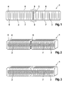
- FIG. 1 shows to explain the disadvantages of the prior art, a conventional connection of two piezo actuators 2 and 3 in the piezoelectric actuator 1.
- the piezoelectric actuator 2 and the piezoelectric actuator 3 are connected in series in the mechanical effective direction, so that a mechanical stroke in the longitudinal extension of the piezoelectric actuator module 1 can be effected with the piezoelectric elements described in the introduction to the description.
- the piezoelectric elements are formed by internal electrodes 4 of one polarity and internal electrodes 5 of the other polarity and the interposed piezoelectric layers, for reasons of clarity, only such a piezoelectric element at the left end of the piezoelectric actuator 2 provided with the corresponding reference numerals has been.
- Both piezoelectric actuators 2 and 3 are integrally connected to one another at the front sides by means of a splice 6.
- the piezoelectric actuators 2 and 3 of the piezoelectric actuator module 1 each have external electrodes 7 and 8, for example sieve electrodes.
- the outer electrode 7 in each case contacts the inner electrodes 5 and the outer electrode 8 contacts the inner electrodes 4 in each case.
- the outer electrodes 7 and 8 can be applied in an electrically conductive manner by means of vapor phase soldering even before the piezoactuators 2 and 3 are assembled.
- bridges 9, for example screen bridges are present which, for example, are contacted by gap or laser welding to the respective outer electrodes 7 or 8.
- These known bridges 9 after the FIG. 1 As a rule, they consist of folded sieves and therefore protrude out of the geometrical contour of the piezoactuators 2 and 3 over a certain range and therefore form the inhomogeneities which have been found to be disadvantageous in the introduction to the description.
- the piezoelectric actuator module 1 yields FIG. 2 in each case a continuous outer electrode 7 and an outer electrode not visible here for the respective other polarity on the opposite side of the piezoelectric actuators 2 and 3, which is designed here as a sieve electrode.
- the visible outer electrode 7 contacts the inner electrodes 5
- the non-visible outer electrode contacts the inner electrodes 4 here.
- the outer electrode 7 and the opposite outer electrode are applied in an electrically conductive manner by means of vapor phase soldering after the piezoactuators 2 and 3 have been assembled.
- the two piezoelectric actuators are also connected to one another here via a splice 6.
- FIG. 3 shows an embodiment of the piezoelectric actuator module 1 according to the invention, in which the in the FIG. 2 Adhesive 6 has fallen away and the two piezoelectric actuators 2 and 3 are non-positively abutting.
- the piezoelectric actuators 2 and 3 are thus held together mechanically via the common outer electrode 7 and the opposite outer electrode and have a joint function on the abutting end faces within certain limits.
Landscapes
- Engineering & Computer Science (AREA)
- Manufacturing & Machinery (AREA)
- Fuel-Injection Apparatus (AREA)
- General Electrical Machinery Utilizing Piezoelectricity, Electrostriction Or Magnetostriction (AREA)
Applications Claiming Priority (1)
| Application Number | Priority Date | Filing Date | Title |
|---|---|---|---|
| DE102007046314A DE102007046314A1 (de) | 2007-09-27 | 2007-09-27 | Piezoaktormodul mit mehreren untereinander verbundenen Piezoaktoren und ein Verfahren zu dessen Herstellung |
Publications (2)
| Publication Number | Publication Date |
|---|---|
| EP2043171A2 true EP2043171A2 (fr) | 2009-04-01 |
| EP2043171A3 EP2043171A3 (fr) | 2010-01-27 |
Family
ID=40227860
Family Applications (1)
| Application Number | Title | Priority Date | Filing Date |
|---|---|---|---|
| EP08105328A Withdrawn EP2043171A3 (fr) | 2007-09-27 | 2008-09-12 | Module de piézoactionneur comprenant plusieurs piézoactionneurs reliés ensembles et son procédé de fabrication |
Country Status (2)
| Country | Link |
|---|---|
| EP (1) | EP2043171A3 (fr) |
| DE (1) | DE102007046314A1 (fr) |
Cited By (1)
| Publication number | Priority date | Publication date | Assignee | Title |
|---|---|---|---|---|
| CN103370804A (zh) * | 2011-04-05 | 2013-10-23 | 本田技研工业株式会社 | 层叠压电体 |
Families Citing this family (1)
| Publication number | Priority date | Publication date | Assignee | Title |
|---|---|---|---|---|
| DE102019201650A1 (de) | 2019-02-08 | 2020-08-13 | Pi Ceramic Gmbh | Verfahren zur Herstellung eines piezoelektrischen Stapelaktors und piezoelektrischer Stapelaktor, vorzugsweise hergestellt nach dem Verfahren |
Citations (2)
| Publication number | Priority date | Publication date | Assignee | Title |
|---|---|---|---|---|
| DE10026005A1 (de) | 2000-05-25 | 2001-12-06 | Bosch Gmbh Robert | Piezoaktor |
| DE10217361A1 (de) | 2001-04-19 | 2002-12-05 | Denso Corp | Piezoelektrisches Element und damit versehene Einspritzdüse |
Family Cites Families (5)
| Publication number | Priority date | Publication date | Assignee | Title |
|---|---|---|---|---|
| US5089739A (en) * | 1990-03-19 | 1992-02-18 | Brother Kogyo Kabushiki Kaisha | Laminate type piezoelectric actuator element |
| DE10201943A1 (de) * | 2001-02-15 | 2002-10-24 | Ceramtec Ag | Vielschichtaktor mit versetzt angeordneten Kontaktflächen gleich gepolter Innenelektroden für ihre Außenelektrode |
| DE10335023A1 (de) * | 2003-07-31 | 2005-02-17 | Robert Bosch Gmbh | Piezoaktor und ein Verfahren zu dessen Herstellung |
| DE102006001134A1 (de) * | 2006-01-09 | 2007-07-12 | Robert Bosch Gmbh | Piezoaktor |
| DE102008004227A1 (de) * | 2008-01-14 | 2009-07-16 | Robert Bosch Gmbh | Piezoaktormodul mit mehreren Piezoaktoren und ein Verfahren zu dessen Herstellung |
-
2007
- 2007-09-27 DE DE102007046314A patent/DE102007046314A1/de not_active Withdrawn
-
2008
- 2008-09-12 EP EP08105328A patent/EP2043171A3/fr not_active Withdrawn
Patent Citations (2)
| Publication number | Priority date | Publication date | Assignee | Title |
|---|---|---|---|---|
| DE10026005A1 (de) | 2000-05-25 | 2001-12-06 | Bosch Gmbh Robert | Piezoaktor |
| DE10217361A1 (de) | 2001-04-19 | 2002-12-05 | Denso Corp | Piezoelektrisches Element und damit versehene Einspritzdüse |
Cited By (2)
| Publication number | Priority date | Publication date | Assignee | Title |
|---|---|---|---|---|
| CN103370804A (zh) * | 2011-04-05 | 2013-10-23 | 本田技研工业株式会社 | 层叠压电体 |
| EP2696382A4 (fr) * | 2011-04-05 | 2014-10-08 | Honda Motor Co Ltd | Corps piézoélectrique laminé |
Also Published As
| Publication number | Publication date |
|---|---|
| EP2043171A3 (fr) | 2010-01-27 |
| DE102007046314A1 (de) | 2009-04-02 |
Similar Documents
| Publication | Publication Date | Title |
|---|---|---|
| EP2043170A2 (fr) | Module de piézoactionneur comprenant plusieurs piézoactionneurs reliés ensembles et son procédé de fabrication | |
| DE102004050803A1 (de) | Piezoaktor | |
| DE102012207276B4 (de) | Vollaktiver Piezostack mit Passivierung | |
| EP2034533B1 (fr) | Module de piézoactionneur comprenant plusieurs piézoactionneurs connectés en série | |
| EP2043171A2 (fr) | Module de piézoactionneur comprenant plusieurs piézoactionneurs reliés ensembles et son procédé de fabrication | |
| DE102007004874A1 (de) | Piezoaktor, bestehend aus übereinander gestapelten, elektrisch kontaktierten Piezoelementen | |
| WO2006089818A1 (fr) | Module actionneur dote d'un actionneur piezo-electrique | |
| DE102008003840A1 (de) | Piezoaktor mit flexiblen Außenelektroden | |
| EP1503435B1 (fr) | Méthode de fabrication d'un actionneur piézo-électrique | |
| EP2071644B1 (fr) | Dispositif avec un actionneur piézoélectrique comprenant une multiplicité de parties actives et/ou de parties détectrices supplémentaires | |
| EP2031669B1 (fr) | Module d'actionneur piézoélectrique comprenant une enveloppe du piézoactionneur et son procédé de fabrication | |
| DE102024004495B4 (de) | Gerät mit Vorrichtung zur Erzeugung eines haptischen Signals, und Verfahren zur Herstellung des Geräts | |
| DE102007053303A1 (de) | Piezoaktor und Piezoaktormodul mit einem Schutzschichtsystem | |
| DE102008004227A1 (de) | Piezoaktormodul mit mehreren Piezoaktoren und ein Verfahren zu dessen Herstellung | |
| DE102024102978B3 (de) | Vorrichtung zur Erzeugung eines haptischen Signals, Gerät mit der Vorrichtung und Verfahren zur Herstellung der Vorrichtung | |
| EP2149921B1 (fr) | Piézoactionneur doté de zones passives à la tête et/ou au pied | |
| EP1926156A2 (fr) | Piézoacteur doté de piézoéléments empilés les uns sur les autres | |
| EP2149922A2 (fr) | Piézoactionneur doté de zones passives à la tête et/ou au pied | |
| DE102007044751A1 (de) | Piezoaktormodul mit mehreren Piezoaktoren | |
| DE102005045229A1 (de) | Anordnung mit einem Piezoaktor und ein Verfahren zu dessen Herstellung | |
| DE102006043709A1 (de) | Anordnung eines Piezoaktors in einem Gehäuse | |
| DE102007056553A1 (de) | Verfahren zur Herstellung eines Piezoaktormoduls mit einer Umhüllung und ein so hergestelltes Piezoaktormodul | |
| WO2006058811A1 (fr) | Actionneur piezo-electrique servant a actionner un composant mecanique | |
| EP3116042A1 (fr) | Module de piezoacteur et piezoinjecteur | |
| DE102010001082A1 (de) | Piezoaktor mit passiven Bereichen am Kopf und/oder Fuß |
Legal Events
| Date | Code | Title | Description |
|---|---|---|---|
| PUAI | Public reference made under article 153(3) epc to a published international application that has entered the european phase |
Free format text: ORIGINAL CODE: 0009012 |
|
| AK | Designated contracting states |
Kind code of ref document: A2 Designated state(s): AT BE BG CH CY CZ DE DK EE ES FI FR GB GR HR HU IE IS IT LI LT LU LV MC MT NL NO PL PT RO SE SI SK TR |
|
| AX | Request for extension of the european patent |
Extension state: AL BA MK RS |
|
| PUAL | Search report despatched |
Free format text: ORIGINAL CODE: 0009013 |
|
| AK | Designated contracting states |
Kind code of ref document: A3 Designated state(s): AT BE BG CH CY CZ DE DK EE ES FI FR GB GR HR HU IE IS IT LI LT LU LV MC MT NL NO PL PT RO SE SI SK TR |
|
| AX | Request for extension of the european patent |
Extension state: AL BA MK RS |
|
| 17P | Request for examination filed |
Effective date: 20100727 |
|
| 17Q | First examination report despatched |
Effective date: 20100820 |
|
| AKX | Designation fees paid |
Designated state(s): DE ES FR |
|
| 18D | Application deemed to be withdrawn |
Effective date: 20110401 |
|
| STAA | Information on the status of an ep patent application or granted ep patent |
Free format text: STATUS: THE APPLICATION IS DEEMED TO BE WITHDRAWN |
|
| R18D | Application deemed to be withdrawn (corrected) |
Effective date: 20101231 |