EP2043207A2 - Modusgekoppelte Festkörperlaservorrichtung - Google Patents
Modusgekoppelte Festkörperlaservorrichtung Download PDFInfo
- Publication number
- EP2043207A2 EP2043207A2 EP08017015A EP08017015A EP2043207A2 EP 2043207 A2 EP2043207 A2 EP 2043207A2 EP 08017015 A EP08017015 A EP 08017015A EP 08017015 A EP08017015 A EP 08017015A EP 2043207 A2 EP2043207 A2 EP 2043207A2
- Authority
- EP
- European Patent Office
- Prior art keywords
- state laser
- solid
- mode
- pulse
- mirror
- Prior art date
- Legal status (The legal status is an assumption and is not a legal conclusion. Google has not performed a legal analysis and makes no representation as to the accuracy of the status listed.)
- Ceased
Links
Images



Classifications
-
- H—ELECTRICITY
- H01—ELECTRIC ELEMENTS
- H01S—DEVICES USING THE PROCESS OF LIGHT AMPLIFICATION BY STIMULATED EMISSION OF RADIATION [LASER] TO AMPLIFY OR GENERATE LIGHT; DEVICES USING STIMULATED EMISSION OF ELECTROMAGNETIC RADIATION IN WAVE RANGES OTHER THAN OPTICAL
- H01S3/00—Lasers, i.e. devices using stimulated emission of electromagnetic radiation in the infrared, visible or ultraviolet wave range
- H01S3/10—Controlling the intensity, frequency, phase, polarisation or direction of the emitted radiation, e.g. switching, gating, modulating or demodulating
- H01S3/11—Mode locking; Q-switching; Other giant-pulse techniques, e.g. cavity dumping
- H01S3/1106—Mode locking
- H01S3/1112—Passive mode locking
- H01S3/1115—Passive mode locking using intracavity saturable absorbers
- H01S3/1118—Semiconductor saturable absorbers, e.g. semiconductor saturable absorber mirrors [SESAMs]; Solid-state saturable absorbers, e.g. carbon nanotube [CNT] based
-
- H—ELECTRICITY
- H01—ELECTRIC ELEMENTS
- H01S—DEVICES USING THE PROCESS OF LIGHT AMPLIFICATION BY STIMULATED EMISSION OF RADIATION [LASER] TO AMPLIFY OR GENERATE LIGHT; DEVICES USING STIMULATED EMISSION OF ELECTROMAGNETIC RADIATION IN WAVE RANGES OTHER THAN OPTICAL
- H01S3/00—Lasers, i.e. devices using stimulated emission of electromagnetic radiation in the infrared, visible or ultraviolet wave range
- H01S3/05—Construction or shape of optical resonators; Accommodation of active medium therein; Shape of active medium
- H01S3/08—Construction or shape of optical resonators or components thereof
- H01S3/08059—Constructional details of the reflector, e.g. shape
-
- H—ELECTRICITY
- H01—ELECTRIC ELEMENTS
- H01S—DEVICES USING THE PROCESS OF LIGHT AMPLIFICATION BY STIMULATED EMISSION OF RADIATION [LASER] TO AMPLIFY OR GENERATE LIGHT; DEVICES USING STIMULATED EMISSION OF ELECTROMAGNETIC RADIATION IN WAVE RANGES OTHER THAN OPTICAL
- H01S2301/00—Functional characteristics
- H01S2301/08—Generation of pulses with special temporal shape or frequency spectrum
- H01S2301/085—Generation of pulses with special temporal shape or frequency spectrum solitons
-
- H—ELECTRICITY
- H01—ELECTRIC ELEMENTS
- H01S—DEVICES USING THE PROCESS OF LIGHT AMPLIFICATION BY STIMULATED EMISSION OF RADIATION [LASER] TO AMPLIFY OR GENERATE LIGHT; DEVICES USING STIMULATED EMISSION OF ELECTROMAGNETIC RADIATION IN WAVE RANGES OTHER THAN OPTICAL
- H01S3/00—Lasers, i.e. devices using stimulated emission of electromagnetic radiation in the infrared, visible or ultraviolet wave range
- H01S3/05—Construction or shape of optical resonators; Accommodation of active medium therein; Shape of active medium
- H01S3/08—Construction or shape of optical resonators or components thereof
-
- H—ELECTRICITY
- H01—ELECTRIC ELEMENTS
- H01S—DEVICES USING THE PROCESS OF LIGHT AMPLIFICATION BY STIMULATED EMISSION OF RADIATION [LASER] TO AMPLIFY OR GENERATE LIGHT; DEVICES USING STIMULATED EMISSION OF ELECTROMAGNETIC RADIATION IN WAVE RANGES OTHER THAN OPTICAL
- H01S3/00—Lasers, i.e. devices using stimulated emission of electromagnetic radiation in the infrared, visible or ultraviolet wave range
- H01S3/05—Construction or shape of optical resonators; Accommodation of active medium therein; Shape of active medium
- H01S3/08—Construction or shape of optical resonators or components thereof
- H01S3/08004—Construction or shape of optical resonators or components thereof incorporating a dispersive element, e.g. a prism for wavelength selection
-
- H—ELECTRICITY
- H01—ELECTRIC ELEMENTS
- H01S—DEVICES USING THE PROCESS OF LIGHT AMPLIFICATION BY STIMULATED EMISSION OF RADIATION [LASER] TO AMPLIFY OR GENERATE LIGHT; DEVICES USING STIMULATED EMISSION OF ELECTROMAGNETIC RADIATION IN WAVE RANGES OTHER THAN OPTICAL
- H01S3/00—Lasers, i.e. devices using stimulated emission of electromagnetic radiation in the infrared, visible or ultraviolet wave range
- H01S3/05—Construction or shape of optical resonators; Accommodation of active medium therein; Shape of active medium
- H01S3/08—Construction or shape of optical resonators or components thereof
- H01S3/08004—Construction or shape of optical resonators or components thereof incorporating a dispersive element, e.g. a prism for wavelength selection
- H01S3/08009—Construction or shape of optical resonators or components thereof incorporating a dispersive element, e.g. a prism for wavelength selection using a diffraction grating
-
- H—ELECTRICITY
- H01—ELECTRIC ELEMENTS
- H01S—DEVICES USING THE PROCESS OF LIGHT AMPLIFICATION BY STIMULATED EMISSION OF RADIATION [LASER] TO AMPLIFY OR GENERATE LIGHT; DEVICES USING STIMULATED EMISSION OF ELECTROMAGNETIC RADIATION IN WAVE RANGES OTHER THAN OPTICAL
- H01S3/00—Lasers, i.e. devices using stimulated emission of electromagnetic radiation in the infrared, visible or ultraviolet wave range
- H01S3/05—Construction or shape of optical resonators; Accommodation of active medium therein; Shape of active medium
- H01S3/08—Construction or shape of optical resonators or components thereof
- H01S3/08018—Mode suppression
- H01S3/0804—Transverse or lateral modes
- H01S3/0805—Transverse or lateral modes by apertures, e.g. pin-holes or knife-edges
-
- H—ELECTRICITY
- H01—ELECTRIC ELEMENTS
- H01S—DEVICES USING THE PROCESS OF LIGHT AMPLIFICATION BY STIMULATED EMISSION OF RADIATION [LASER] TO AMPLIFY OR GENERATE LIGHT; DEVICES USING STIMULATED EMISSION OF ELECTROMAGNETIC RADIATION IN WAVE RANGES OTHER THAN OPTICAL
- H01S3/00—Lasers, i.e. devices using stimulated emission of electromagnetic radiation in the infrared, visible or ultraviolet wave range
- H01S3/05—Construction or shape of optical resonators; Accommodation of active medium therein; Shape of active medium
- H01S3/08—Construction or shape of optical resonators or components thereof
- H01S3/081—Construction or shape of optical resonators or components thereof comprising three or more reflectors
- H01S3/0813—Configuration of resonator
- H01S3/0815—Configuration of resonator having 3 reflectors, e.g. V-shaped resonators
-
- H—ELECTRICITY
- H01—ELECTRIC ELEMENTS
- H01S—DEVICES USING THE PROCESS OF LIGHT AMPLIFICATION BY STIMULATED EMISSION OF RADIATION [LASER] TO AMPLIFY OR GENERATE LIGHT; DEVICES USING STIMULATED EMISSION OF ELECTROMAGNETIC RADIATION IN WAVE RANGES OTHER THAN OPTICAL
- H01S3/00—Lasers, i.e. devices using stimulated emission of electromagnetic radiation in the infrared, visible or ultraviolet wave range
- H01S3/09—Processes or apparatus for excitation, e.g. pumping
- H01S3/091—Processes or apparatus for excitation, e.g. pumping using optical pumping
- H01S3/094—Processes or apparatus for excitation, e.g. pumping using optical pumping by coherent light
- H01S3/09408—Pump redundancy
-
- H—ELECTRICITY
- H01—ELECTRIC ELEMENTS
- H01S—DEVICES USING THE PROCESS OF LIGHT AMPLIFICATION BY STIMULATED EMISSION OF RADIATION [LASER] TO AMPLIFY OR GENERATE LIGHT; DEVICES USING STIMULATED EMISSION OF ELECTROMAGNETIC RADIATION IN WAVE RANGES OTHER THAN OPTICAL
- H01S3/00—Lasers, i.e. devices using stimulated emission of electromagnetic radiation in the infrared, visible or ultraviolet wave range
- H01S3/09—Processes or apparatus for excitation, e.g. pumping
- H01S3/091—Processes or apparatus for excitation, e.g. pumping using optical pumping
- H01S3/094—Processes or apparatus for excitation, e.g. pumping using optical pumping by coherent light
- H01S3/0941—Processes or apparatus for excitation, e.g. pumping using optical pumping by coherent light of a laser diode
- H01S3/09415—Processes or apparatus for excitation, e.g. pumping using optical pumping by coherent light of a laser diode the pumping beam being parallel to the lasing mode of the pumped medium, e.g. end-pumping
-
- H—ELECTRICITY
- H01—ELECTRIC ELEMENTS
- H01S—DEVICES USING THE PROCESS OF LIGHT AMPLIFICATION BY STIMULATED EMISSION OF RADIATION [LASER] TO AMPLIFY OR GENERATE LIGHT; DEVICES USING STIMULATED EMISSION OF ELECTROMAGNETIC RADIATION IN WAVE RANGES OTHER THAN OPTICAL
- H01S3/00—Lasers, i.e. devices using stimulated emission of electromagnetic radiation in the infrared, visible or ultraviolet wave range
- H01S3/14—Lasers, i.e. devices using stimulated emission of electromagnetic radiation in the infrared, visible or ultraviolet wave range characterised by the material used as the active medium
- H01S3/16—Solid materials
- H01S3/1601—Solid materials characterised by an active (lasing) ion
- H01S3/1603—Solid materials characterised by an active (lasing) ion rare earth
- H01S3/1618—Solid materials characterised by an active (lasing) ion rare earth ytterbium
-
- H—ELECTRICITY
- H01—ELECTRIC ELEMENTS
- H01S—DEVICES USING THE PROCESS OF LIGHT AMPLIFICATION BY STIMULATED EMISSION OF RADIATION [LASER] TO AMPLIFY OR GENERATE LIGHT; DEVICES USING STIMULATED EMISSION OF ELECTROMAGNETIC RADIATION IN WAVE RANGES OTHER THAN OPTICAL
- H01S3/00—Lasers, i.e. devices using stimulated emission of electromagnetic radiation in the infrared, visible or ultraviolet wave range
- H01S3/14—Lasers, i.e. devices using stimulated emission of electromagnetic radiation in the infrared, visible or ultraviolet wave range characterised by the material used as the active medium
- H01S3/16—Solid materials
- H01S3/163—Solid materials characterised by a crystal matrix
- H01S3/1675—Solid materials characterised by a crystal matrix titanate, germanate, molybdate, tungstate
Definitions
- the present invention relates to a solid-state laser apparatus, and more specifically to a mode-locked solid-state laser apparatus which is easily downsized and capable of short-pulse operation.
- Solid-state lasers in which a semiconductor laser (LD) is used as the excitation light source and a solid-state laser medium (laser crystal, ceramics, glass, or the like) doped with rare earth ions or transition metal ions is excited by the light source have been actively developed.
- a semiconductor laser LD
- a solid-state laser medium laser crystal, ceramics, glass, or the like
- rare earth ions or transition metal ions is excited by the light source
- short pulse lasers that generate so-called short pulse beams in the range from picoseconds to femtoseconds have been sought and proposed in many application fields including medicine, biology, machine industry, and measurement, and some of them are put into practical use after demonstration.
- SESAM semiconductor saturable absorbing mirror
- soliton mode locking which is one of the mode locking regimes
- the combination of negative group velocity dispersion in the laser resonator and self phase modulation mainly in the laser medium enables generation of pulses in the femtosecond region.
- the soliton mode locking is a regime in which mode locking is initiated and the pulses are maintained/stabilized by the semiconductor saturable absorbing mirror, at the same time the mode locked pulses become sharp through soliton pulse forming which occurs by balancing the negative group velocity dispersion with self phase modulation, thereby stable pulse generation becomes possible
- a solid-state laser apparatus that realizes the soliton mode locking includes a solid-state laser medium, a saturable absorbing mirror, and a negative group velocity dispersion element within the resonator.
- the negative group velocity dispersion is also simply referred to as negative dispersion.
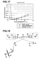
- a typical configuration of conventional soliton mode-locked solid-state laser doped with Yb solid-state laser medium is Yb:KGd(WO 4 ) 2 ) as described in Non-Patent Document 1 is shown in Figure 18 .
- the reference symbol 80 is an excitation light source that emits, for example, 980nm excitation light
- 81 is an input optical system provided for each of a pair of the excitation light sources 80
- 83 is a solid-state laser medium
- M1 and M2 are a pair of concave mirrors forming a resonator with a curvature radius of, for example, 20cm
- 84 is a concave mirror with a curvature radius of 20cm
- 85 is a SESAM
- 86 and 87 are prisms forming a prism pair made of, for example, SF10 glass
- 88 is a knife edge plate
- 89 is an output coupler with a transmittance of, for example, 4.3%.
- the conventional apparatus employs a configuration in which the beam radius of the laser oscillation light is focused separately at the solid-state medium and SESAM by the concave mirrors M1, M2, and 84, in order to reduce the beam radius ⁇ L at the laser medium and the beam radius ⁇ A at the SESAM.
- the spot sizes on the laser medium and SESAM are reduced for the following two reasons. First reason is to reduce the threshold value of laser oscillation, and the second reason is to satisfy the soliton mode locking condition.
- the laser oscillation threshold P th is represented by Formula (1) below as described, for example, in Applied Optics, Vol. 36, No. 9, pp. 1867-1874, 1997 (Non-Patent Document 2).
- P th ⁇ h ⁇ P ⁇ ⁇ L 2 + ⁇ P 2 4 ⁇ ⁇ a ⁇ f 1 + f 2 ⁇ L i + T OC + 2 ⁇ f 1 ⁇ ⁇ N 0 ⁇ ls
- ⁇ p is the excitation light beam radius at the solid-state medium
- h ⁇ p is the excitation light photon energy
- ⁇ is the cross-section of stimulated emission of the solid-sate laser medium
- ⁇ is the upper level life time
- ⁇ a is the absorption efficiency
- f 1 is the lower level occupancy
- f 2 is the upper level occupancy
- L i is the intracavity loss of the resonator
- T oc is the output mirror transmittance
- No is the rare earth i
- Formula (1) above shows that it is only necessary to reduce the oscillation beam radius ⁇ L and excitation light beam radius ⁇ P in the solid-state laser medium in order to reduce the oscillation threshold.
- the Q-switched mode locking is an operation mode in which a mode-locked pulse train (frequency in the range from 10MHz to 1GHz, pulse width in the range from picoseconds to femtoseconds) is disposed in a long pulse of Q-switched pulse (frequency in the range from 1KHz to several 100 KHz, pulse width in the range from microseconds to nanoseconds).
- E p is the intracavity pulse energy
- ⁇ R is the modulation depth of the saturable absorption mirror
- F sat,A is the saturated fluence of the saturable absorption mirror
- hv is the oscillation laser photon energy
- g is the laser gain of the laser medium
- K is the following.
- n 2 is the nonlinear refraction index of the laser medium
- D is the total group velocity dispersion of the entire resonator for one round trip (D ⁇ 0)
- ⁇ 0 is the center frequency of the oscillation light
- ⁇ G is the gain bandwidth.
- Formula (2) shows that it is necessary to reduce the beam cross section at the laser medium and the beam cross-section at the SESAM, and/or to increase the intracavity pulse energy E p in order to avoid generation of the Q-switched mode locking.
- the conventional mode-locked solid-state laser apparatuses structured in the manner as described above require at least three concave mirrors, and in some cases further require a plurality of mirrors for beam replication. This increases the number of optical components of the mode-locked solid-state laser, and the apparatus cost is increased.
- the distance between the concave mirror and the laser medium, and between the concave mirror and SESAM is usually set to a value about half the curvature radius, which alone amounts to about 150mm (when curvature radius is 100mm) to 300mm (when curvature radius is 200mm) in total.
- the resonator requires a length of about 500mm to 1m, so that the laser apparatus inevitably become large.
- the negative dispersion is provided by the prism pair of prisms 86 and 87, and the distance between the prisms is 450mm.
- the conventional apparatuses have low laser oscillation stability.
- Patent Document 1 proposes a mode-locked solid-state laser apparatus downsized by disposing the solid-state laser medium and SESAM in close proximity to each other.
- Patent Document 2 proposes a mode-locked solid-state laser apparatus in which a saturable absorption mirror is formed on a solid-state laser medium by coating and a negative dispersion mirror doubles as the output mirror to reduce the number of optical components and to downsize the apparatus.
- phase jumping occurs in the lightwave field inside thereof which produces a "node” where the field intensity falls to 0.
- a spatial stripe pattern of laser lightwave intensity is developed in the laser medium by the phase jumping, which is called the spatial hole burning.
- Reference Document 1 describes that where the laser medium is disposed adjacent to the reflection mirror, a depression occurs in the gain spectrum, and it causes instability of the soliton pulses moving round inside the resonator. More specifically, the spatial hole burning effects appear more strongly adjacent to the reflection mirror, so that the gain stripe pattern developed in the laser medium by the spatial hole burning leads to modulation of the gain spectrum in the frequency domain. Eventually, the gain is preferentially given to phenomena (shift pulse, double pulse, CW background) competing with the desired pulse. This causes the desired soliton pulse to lose the competition and the pulse phenomena described above to occur, leading to the instability.
- Patent Document 1 and Patent Document 2 do not describe the influence of spatial hole burning to the mode stability in any way, and do not disclose any measure for stabilizing the mode.
- Reference Document 1 discusses only the 700fsec pulse operation in 1030nm oscillation in a LD-excited Yb:YAG laser. Furthermore, it discusses only the operation in a high output power region of several tens of watts.
- Mode stabilization conditions for other transition elements that can be expected to provide short pulses in the range from 100 to 200fsec for example, 1050nm oscillation of Yb:YAG, Yb:KYW(Yb:KY(WO 4 ) 2 ) crystal, Yb:KGW(Yb:KGd(WO 4 ) 2 ) crystal, Yb:Y 2 O 3 , Yb:Sc 2 O 3 , Yb:Lu 2 O 3 , Er,Yb:glass, Nd:glass are not discussed in any way.
- the present invention has been developed in view of the circumstances described above, and it is an object of the present invention to define the conditions of stabilizing mode-locked operation and to provide a small, low cost, and highly stable solid-state laser apparatus capable of realizing femtosecond CW mode locking.
- a mode-locked solid-state laser apparatus of the present invention is a soliton mode-locked solid-state laser apparatus having a resonator which includes therein a solid-state laser medium, a saturable absorption mirror, and a negative group velocity dispersion element, wherein:
- the referent of "not greater than twice the Rayleigh length" may include a case in which the distance between them is 0, that is, the saturable absorption mirror and the solid-state laser medium are brought into close contact with each other.
- the referent of "operation modes other than a fundamental period soliton pulse” means competitive pulses generated in competition with the fundamental period soliton pulse in the resonator, such as a double pulse, CW background, and the like (Fiugre 3).
- the shift pulse has identical pulse bandwidth and pulse energy to those of the fundamental soliton pulse, but the center frequency thereof is shifted by ⁇ shift in comparison with the fundamental soliton pulse.
- the CW background is not a pulse but a component operating in continuous wave in the time domain, and appears as a narrow linewidth in spectrum.
- the double pulse is a two-pulse train, each having half energy and a half pulse bandwidth of the fundamental soliton pulse. All of these are frequency shifted from the fundamental soliton, but the CW background and double pulse are depicted with a shift amount of 0 in Figure 3 for clarity.
- the shift pulse is a pulse that can not be suppressed by the absorption modulation depth of the saturable absorption mirror and not included in the referent of "operation modes other than a fundamental period soliton pulse" above.
- the total intracavity dispersion amount D is expressed as the relational expression described above in relation to the pulse width (note that the pulse width is inversely proportional to the pulse bandwidth), which is set to a value in the range obtained from the pulse bandwidth in which competitive pulses generated by spatial hole burning effects (double pulse and CW background) can be suppressed at an absorption modulation depth of the saturable absorption mirror set to a predetermined value not less than 0.4%.
- the inventors of the present invention have found, in the process of downsizing a mode-locked solid-state laser apparatus, that soliton mode-locked pulses can be generated even in a configuration that does not form the beam waist on the laser medium by disposing the laser medium and SESAM at a distance not greater than twice a Rayleigh length.
- the inventors of the present invention have found that there are certain restrictions on the absorption modulation depth of the saturable absorption mirror and the total intracavity dispersion amount for mode stablity when the apparatus is structured small, and have clarified the restrictions.
- the present invention covers a system in which spatial hole burning effects are present, and a system in which the laser medium is disposed near the center of the resonator and the spatial hole burning effects can be ingored as described, for example, Non-Patent Document 3 is outside of the scope of the present invention.
- the mode-locked solid-state laser apparatus of the present invention is structured such that excitation light for exciting the solid-state laser medium is inputted at an angle to the optical axis of the resonator, and reflected by a dichroic mirror, which is disposed on the optical axis or an extension thereof and transmits solid-state laser oscillation light, to propagate in a direction of the optical axis.
- the referent of "inputted at an angle” includes a case in which the excitation light is inputted from a direction perpendicular to the optical axis.
- the solid-state laser medium is a laser medium doped with a rare earth.
- a rare earth may be ytterbium (Yb), erbium (Er), or neodymium (Nd).
- the solid-state laser medium doped with a rare earth include Yb:YAG(Y 3 Al 5 O 12 ), Yb:KYW(K(WO 4 ) 2 ), Yb:KGW(KGd(WO 4 ) 2 ), Yb:Y 2 O 3 , Yb:Sc 2 O 3 , Yb:Lu 2 O 3 , Er,Yb:glass, Nd:glass, and the like.
- the resonator is structured as a linear resonator.
- a cavity mode waist diameter is not greater than 100 ⁇ m.
- the "diameter” is defined as an area in which light intensity is not less than 1/e 2 of the maximum intensity in a beam intensity distribution on a cross section orthogonal to the light travelling direction.
- the negative group velocity dispersion element either one of a prism pair, a diffraction grating pair, and a negative dispersion mirror pair or a combination of two or more of them is preferably used.
- a transmission type negative group velocity dispersion mirror having also an output mirror function of the resonator is used as the negative velocity dispersion element.
- the total intracavity dispersion amount D is in the range from -2500 fsec 2 to less than 0 fsec 2 .
- the total intracavity dispersion amount D is in the range from -5750 fsec 2 to less than 0 fsec 2 .
- the total intracavity dispersion amount D is in the range from -1750 fsec 2 to less than 0 fsec 2 .
- the total intracavity dispersion amount D is in the range from -3250 fsec 2 to less than 0 fsec 2 .
- the total intracavity dispersion amount D is in the range from -3000 fsec 2 to less than 0 fsec 2 .
- the total intracavity dispersion amount D is in the range from -3000 fsec 2 to less than 0 fsec 2 .
- the total intracavity dispersion amount D is in the range from -1200 fsec 2 to less than 0 fsec 2 .
- the resonator length is preferable to be not greater than 200mm, more preferably not greater than 100mm, further preferably not greater than 75mm, and most preferably not greater than 50mm.
- FIG. 1 A basic configuration of a mode-locked solid-state laser apparatus, to be described later in detail, is shown in Figure 1 .
- a solid-state laser medium 15 and a saturable absorption mirror 16 are disposed in close contact with each other or in close proximity to each other at a distance at a distance not greater than twice a Rayleigh length determined by a cavity mode waist diameter formed on the saturable absorption mirror 16. This allows a beam waist to be formed on the saturable absorption mirror 16 with less number of mirrors, that is, with the concave output mirror and saturable absorption mirror at the least, and the solid-state laser medium to be disposed adjacent thereto.
- the beam spots (A eff A , A eff L ) at the solid-state laser medium and saturable absorption mirror can be reduced, which allows the resonator length to be reduced sufficiently, so that a small and stable CW mode-locked laser can be realized.
- soliton pulse can be stably generated by setting the absorption modulation depth of the saturable absorption mirror not less than 0.4%, and setting the total intracavity dispersion amount
- the inventors have also disclosed that a totol intracavity dispersion amount of as much as minus several tens of thousands of fsec 2 is required in some cases.
- the mode-locked solid-state laser apparatus is particularly preferable if structured such that excitation light for exciting the solid-state laser medium is inputted at an angle to the optical axis of the resonator and reflected by a dichroic mirror, which is disposed on the optical axis or an extension thereof and transmits solid-state laser oscillation light, to propagate in a direction of the optical axis, since in that case the excitation optical system is downsized sufficiently.
- FIG. 1 is a schematic side view of a soliton mode-locked solid-state laser apparatus according to an embodiment of the present invention.
- the mode locked solid-state laser apparatus includes a semiconductor laser 11 that emits excitation light (pumping light) 10, an excitation optical system 12 that inputs the excitation light 10 into a resonator, a dichroic mirror 13 disposed on an extension of the optical axis of a resonator, to be described later, in the subsequent stage of the excitation optical system 12, a concave output mirror 14 constituting one end of the resonator, a SESAM (semiconductor saturable absorption mirror) 16 constituting the other end of the resonator, a solid-state laser medium 15 disposed inside of the resonator formed by the SESAM 16 and output mirror 14, and a negative dispersion element 17 also disposed inside of the resonator.
- a semiconductor laser 11 that emits excitation light (pumping light) 10
- an excitation optical system 12 that
- a Yb:KYW crystal is used, by way of an example, as the solid-state laser medium 15.
- the semiconductor laser 11 a semiconductor laser that emits excitation light 10 with a wavelength of 980nm is used for exciting the solid-state laser medium 15.
- the dichroic mirror 13 a dichroic mirror that transmits the excitation light 10 with a wavelength of 980m and reflects solid-state laser oscillation light 18 with a wavelength of 1045nm is used.
- the negative dispersion element 17 one of a prism pair, a diffraction grating pair, and a negative dispersion mirror like those described above or a combination of two or more of them is used.
- the solid-state laser medium 15 and SESAM 16 are disposed in close contact with each other or in close proximity within a distance d which is not greater than twice the Rayleigh length determined by a resonator mode radius (beam radius of oscillation light) formed on the SESAM 16.
- the solid-state laser medium 15 is excited by the excitation light 10 entered in the resonator by transmitting through the dichroic mirror 13 and output mirror 14, and 1045nm light generated by the excitation is oscillated by the operation of the resonator.
- a portion of the solid-state laser oscillation light 18 transmits through the output mirror 14 and is reflected by the dichroic mirror 13, thereby deflected from the optical path of the excitation light 10 and outputted to the outside.
- dichroic mirror disposed outside of the resonator another configuration may also be adopted in which the excitation light 10 is reflected and guided inside of the resonator by the dichroic mirror, and the oscillation light 18 is transmitted through the dichroic mirror and outputted to the outside.
- the negative group velocity dispersion by the operation of the negative dispersion element 17 in the laser resonator and the self phase modulation mainly in the solid-state laser medium 15 are combined, thereby the pulse oscillation light 18 in the femtosecond region is obtained.
- mode locking is initiated by the SESAM 16 to maintain and stabilize the pulses, and at the same time the mode-locked pulses become sharp through soliton pulse forming which occurs by balancing the group velocity dispersion with the self phase modulation, thereby stable femtosecond-class soliton pulse generation becomes possible.
- the Rayleigh length is 1. 9mm, hence twice the Rayleigh length is 3.8mm. If the oscillation threshold is kept below or equal to 100mW, sufficiently high efficiency oscillation may be realized.
- Such increase does not pose any problem to realize CW mode locking as long as the oscillation threhsold is kept below or equal to 100mW.
- disposition of the solid-state laser medium and SESAM at a distance not greater than twice the Rayleigh length allows to satisfy Formulae (1) and (2) above, and to downsize the mode-locked solid-state laser apparatus. That is, disposition of the solid-state laser medium and SESAM at the aforementioned distance allows to configure a samll solid-state laser apparatus capable of generating soliton pulses.
- the inventors of the present invention have revealed that the competitive pulses generated by the spatial hole burning can be supressed and stable soliton pluse operation can be realized by setting the absorption modulation depth ⁇ R of the SESAM and total intracavity dispersion D to values within predetermined ranges respectively.
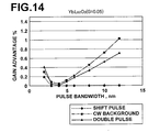
- FIG 4 there is shown the dependency of the gain advantages ⁇ G of competitive pulses generated by spatial hole burning on the spectrum bandwidth ⁇ p (in terms of wavelength bandwidth) of a soliton pulse calculated for a Tb:KYW crystal.
- the gain advantage ⁇ G is obtained by the inventors of the present invention using the formula described in Reference Document 1 with respect to a mode-locked solid-state laser apparatus structured in the manner shown in Figure 1 .
- the horizontal axis of the graph represents the spectrum bandwidth (pulse bandwidth) ⁇ p of a soliton pulse in laser oscillation.
- the gain advantage as used herein means a gain difference between each competitive process (shift pulse, CW background, double pulse) and soliton pulse.
- Figure 4 shows that these competitive processes always have slightly higher gains than the soliton pulse. In order to obtain CW mode locking with desired fundamental soliton, it is necessary to suppress these competitive pulses.
- the CW background and double pulse can be suppressed in the pulse bandwidth in Figure 4 that satisfies ⁇ G (CW) ⁇ ⁇ R/2 and ⁇ G (DP) ⁇ ⁇ R/S.
- shift pulse can not be suppressed by the SESAM.
- the shift pulse has equivalent pulse width, pulse bandwidth, and energy to those of the fundamental soliton pulse and shifted on the frequency axis (Table 1 and Figure 3 ), which gives the same saturation level to the SESAM so that they can not be discriminated by the SESAM.
- soliton mode can be stably generated in a pulse bandwidth where the gain advantage ⁇ G of the shift pulse is nearly 0, and satisfies ⁇ G (CW) ⁇ ⁇ R/2 and ⁇ G (DP) ⁇ ⁇ R/S.
- CW gain advantage
- DP ⁇ G
- the lower limit of pulse bandwidth where the soliton mode can be stably generated is restricted by shift pulse because it can not be suppressed by the SESAM.
- the pulse width ⁇ p can be related to the absolute value
- ⁇ P 1.76
- restriction on the pulse bandwidth for stable soliton mode is equivalent to the restriction on the total intracavity dispersion amount and it is necessary to set the intracavity dispersion amount D to a value in an appropriate range according to the absorption depth of the SESAM in order to stably generate soliton mode by suppressing spatial hole burning.
- Figure 5 illustrates the dependency of the total intracavity dispersion amount on the pulse bandwidth (pulse width is inversely proportional to the pulse bandwidth) obtained from Formula (3) above.
- soliton pulse can be stably generated by providing a saturable absorption mirror having a absorption modulation depth ⁇ R and a saturation level S that satisfy, for the gain advantage G (DP) of the double pulse with respect to the fundamental soliton pulse in the resonator and the gain advantage G (CW) of the CW background with respect to the fundamental soliton pulse, ⁇ G (CW) ⁇ ⁇ R/2 and ⁇ G (DP) ⁇ ⁇ R/S ------- (A), and configuring the apparatus such that the absolute value
- ⁇ R/S 0.075%, which restricts the pulse bandwidth from 4.5 to 6.0nm for stable pulse generation.
- the pulse bandwidth is limited to a value not less than 4nm (the gain advantage of the shift pulse becomes substantially 0 at a pulse bandwidth not less than 4nm, as shown in Figure 4 ).
- ⁇ R 1.4%
- the pulse bandwidth can be broadened as wide as 4 to 11nm which allows generation of a pulse with a pulse width from 287 to 104fsec.
- the absorption modulation depth of the SESAM is set to a predetermined value not less than 0.4% in the manner as described above, there is a restriction on the pulse bandwidth (pulse width) in which the double pulse and CW background can be suppressed by the ⁇ R value.
- the pulse energy E p is approximately 23nJ. This value is the approximate maximum pulse energy envisioned in the present invention (In a small apparatus like that shown in Figure 1 , which is a target apparatus of the present invention, greater pulse energy than this can not be achieved in theory).
- Figure 4 shows that a negative dispersion amount of 950fsec 2 is required in order to generate a 104fsec pulse (which corresponds to a pulse bandwidth of 11nm).
- a negative dispersion amount of about 2500fsec 2 is sufficient.
- the total intracavity dispersion amount is also a function of the pulse energy E P , so that the greater pulse energy requires a greater amount of dispersion. Therefore, this value is the upper limit of the absolute total intracavity dispersion amount for an apparatus envisioned in the present invention.
- the lower limit of the absolute value is determined to a value greater than 0, since reduced pulse energy requires a reduced total intracavity dispersion amount by that much, and the total intracavity dispersion amount may become 0, as shown in Figure 4 .
- the total intracavity dispersion amount D needs to be a value in the range from -2500fsec 2 to less than 0. Note that the total intracavity dispersion amount D is further restricted depending on the apparatus configuration.
- the total intracavity dispersion amount D should fall within the range from -2500 to -1400 fsec 2
- the absolute value of a maximum dispersion amount of commericially avaialbe dispersion mirrors is 1200fseC 2 , and if trying to provide the dispersion by one such mirror, it is necessary to set the ⁇ R so that the stable condition is obtained preferably with an absolute value not greater than 1200fsec 2 . This holds true for other laser materials.
- the dispersion amount is set to an absolute value greater than 1200fsec 2 , this is realized by providing a plurality of dispersion mirrors as in the embodiments shown in Figures 7 and 8 to be described later.
- the solid-state laser medium 15 is made of Yb:KYW, but the identical calculation results to those shown in Figures 4 and 6 are obtained for a Yb:KGW crystal with respect to the gain advantages of competitive pulses to the fundamental soliton pulse.
- Yb:KYW and Yb:KGW have identical physical property constants, such as the fluorescence bandwidth, stimulated emission cross section, absorption cross section, and the like.
- the total intracavity dispersion amount needs to be increased by 2.3 times in comparison with the case in which Yb:KYW is used in terms of absolute value. That is, when the solid-state laser medium is Yb:KGW, the desirable range of the total amount of intractivity dispersion D is from -5750 to less than 0fsec 2 .
- the resonator length is assumed to be 50mm, but both the stability of mode locking and the stability of laser resonator can be achieved if the resonator length is not greater than 200mm.
- a longer resonator length reduces the pulse repetitions and increases the pulse energy which exceeds the CW mode locking threshold easily. That is, if only Formula (2) above with respect to the CW mode locking is considered, it can be said that a greater pulse energy is preferable, and hence a longer resonator length is preferable.
- the resonator length can not be increased indefinitely.
- the mechanical limit which is obtained from the following considerations.
- the alignment allowance of the resonator is inversely proportional to the resonator length, and is a function of the mirror curvature. It is known that the alignment allowance in a 1m class apparatus is about 50 to 100 ⁇ rad as described, for example, in the literature by N.Hodgson and H. Weber, Optical Resonators, p.219, Springer.
- the allowance may be increased by five times from 250 to 500 ⁇ rad.
- the mechanical variations of the mirror can not be quantified easily but for a typical gimbal, it is 50 ⁇ rad (with a temerature variation of 8 degrees Centigrade, catalog of Newport Corporation), which shows that a mirror variation comparable to the allowance occurs in an 1m class resonator. If the resonator length is reduced to a value not greater than 200mm, however, the mirror variation is reduced to about 1/5 of the allowance, and output power variation is reduced to a neglibible level.
- the resonator length is not greater than 200mm for satisfying both of them.
- the excitation optical system 12 for focusing the excitation light 10 at the solid-state laser medium 15 can be structured such that the excitation light 10 is inputted at an angle to the optical axis of the resonator through the dichroic mirror 13, as shown in Figure 2 .
- This allows a simple excitation optical system of one gradient index lens to be used, so that a significantly small mode-locked solid-state laser apparatus can be formed. That is, the distance from the excitation light source to the laser medium can be reduced in comparison with the configuration of Figure 1 , so that the excitation optical system can be structured small and simple.
- the negative dispersion element 17 shown in Figure 2 a prism pair of prisms 20, 21 as illustrated in an embodiment of Figure 7 and a negative dispersion mirror pair of negative dispersion mirrors 30, 31 illustrated in an embodiment of Figure 8 may be used.
- the negative dispersion element is not limited to these, and any element if it provides negative dispersion may be used, such as a negative dispersion fiber or a diffraction grating pair.
- Non-Patent Document 3 a chirp mirror which is a mirror having a dielectric multilayer film coated thereon that allows each wavelength to ingress to a different depth ( literature, Laser Engineering, Vol. 27, No. 11, pp.
- GTI Green-Tournois Interferometer
- literature, IEEE, Transaction on Quantum Electronics, Vol. 22, No. 1 (1986) pp. 182-185 literature, IEEE, Transaction on Quantum Electronics, Vol. 22, No. 1 (1986) pp. 182-185
- the negative dispersion amount is defined in net round-trip amount considering the contribution of positive dispersion in the resonator (laser medium, ordinary mirror, SESAM).
- the output mirror 14 may double as a negative dispersion mirror 17' by applying a transmission type negative dispersion coating 17A to the mirror surface of the output mirror 14.
- a chirp mirror with a reflectance ratio of 99.8% may be used as the negative dispersion mirror.
- the resonator configuration is a linear type, but not limited to this, and any configuration may be employed as long as the SESAM 16 and solid-state laser medium 15 are brought into contact with each other or disposed in proximity to each other at the distance described above.
- an L-shaped or a V-shaped resonator configuration may be employed.
- the reference numeral 40 denotes a planar mirror for reflecting oscillation light 18
- the reference numeral 50 denotes a concave mirror for reflecting oscillation light 18
- the reference numeral 51 denotes an output mirror.
- a further increase of ⁇ R allows the soliton pulses to be generated stably in a broader pulse bandwidth.
- the pulse bandwidth it is preferable to make it greater than 4nm (corresponding to pulse width of 287fsec). Accordingly, where Yb:YAG is used, it is preferable to satisfy ⁇ R ⁇ 0.8% or greater.
- the solid-state laser medium it is customary to use a single crystal. Recently, in garnet group materials, such as YAG, ceramic state laser media have been produced, and the present invention may use such type of solid-state laser medium. Ceramics have optical characteristics which are comparable or superior to those of a single crystal and can be produced in large sizes, so that cost reductions can be expected. In addition to garnet, a group of so-called C-rare earths can be ceramitized, which include Yb:Y 2 O 3 , Yb:Sc 2 O 3 , Yb:Lu 2 O 3 , and the like ( literature, Optics Express, Vol. 11, No. 22 (2003) pp. 2911-2916 ) .
- Yb:Sc 2 O 3 has a crystal structure and a nonlinear refraction index identical to the crystal structure and nonlinear refraction index of Yb:Lu 2 O 3 so that the identical condition to that of Yb:Lu 2 O 3 is applied to Yb:Sc 2 O 3 .
- the excitation light is absorbed by Yb ions, and the energy is transferred to Er ions through energy transfer.
- the use of the phosphate glass which is a medium having relatively high phonon energy, will result in fast relaxation from excitation level 4 I 11/2 to laser upper level 4 I 13/2 . This allows population inversion to be formed with high efficiency. In this case, the oscillation is near 1550nm, and excitation is 980nm.
- Er/Yb codoped phosphate glass is used as the laser medium, as illustrated in Figure 16 , a configuration may be adopted in which the oscillation light 18 with a wavelength from 1550 to 1600nm is passed through a nonlinear optical crystal 60 to generate a second harmonic 61, as well as outputted directly.
- the oscillation light can be converted to light with a wavelength in the range from 780 to 800nm.
- Conventional solid-state lasers adjacent to 800nm require a transition metal crystal, such as TiSapphire or the like, in addition to a 532nm green laser as the excitation light source.
- the configuration described above allows semiconductor laser excitation in the infrared wavelength region, which provides a benefit that an inherently high efficient rare earth transition can be used.
- the shift pulse becomes approximately 0 at 2nm pulse bandwidth.
- the pulse bandwidth is set to a value not less than 4nm (corresponding to 600fsec pulse width).
- the pulse bandwidth is set to a value not less than 4nm by the same discussion as above.
- a configuration may be adopted in which the excitation light is introduced into the resonator by a dichroic mirror inserted therein, after setting the parameters of elements constituting the resonator.
- This allows the excitation optical system to be made significantly small, simple and low cost, while conventional apparatuses require a large and complicated excitation optical system like that shown in Figure 18 .
- This also leads to stabilization of laser output.
- the excitation was implemented through a mirror constituting the resonator (a concave mirror with a curvature radius of 20cm in Figure 18 ), so that the apparatus became large, complicated, and high cost.
- the excitation light is focused on the solid-state laser medium, it is often the case that the beam spot in the slow axis direction (direction parallel to the emitter) of the excitation semiconductor laser is focused at a magnification approximately from 1:1 to 1:2.
- the concave mirror of the resonator is laid in-between, the distance from the concave mirror to the crystal corresponds approximately to the back focal length of the excitation optical system. In order to realize this by a single lens system, roughly a half the distance or equivalent distance is required in front of the excitation optical system.
- a concave with a curvature radius of about 100 to 200mm is used as the concave mirror, so that the distance between the concave mirror and crystal needs to be half the value, that is, 50 to 100mm.
- the distance from the semiconductor laser to the laser crystal needs to be from 75mm (with concave curvature radius of 100mm and 1:2 focusing) to 200mm (with concave curvature radius of 200mm and 1:1 focusing).
- a plurality lens system is generally used, instead of a single lens system. Since the divergence angle of the fast axis (direction orthogonal to the emitter) of excitation semiconductor laser is large, a collimating and focusing lens system for the fast axis and a collimating and focusing lens system for the slow axis are generally used. In such a configuration, at least three to four lenses are required, including a fast axis collimating lens, a slow axis collimating lens (and possibly a slow axis magnifying lens), and a focusing lens. As described above, the excitation through a resonator mirror poses a problem that the excitation optical system tends to become large and complicated.
- the dichroic mirror applied to the present invention is a mirror that generally reflects the excitation light with high reflectance (reflectance ratio greater than 85%) and transmits the laser oscillation light without reflection (reflectance ratio smaller than 0.5%). Consequently, degradation in laser oscillation efficiency due to insertion of the mirror is minimized and the use of the dichroic mirror offers an advantage that the excitation light source can be moved closer to the solid-state laser medium in comparison with the conventional optical system. Note that, 45 degree incidence or Brewster's angle incidence is preferable for the dichroic mirror. The dichroic mirror only requires application of coating design according to the incident angle of the excitation light.
- the dichroic mirror allows the use of a single lens, such as a graded-index lens (GRIN lens) or the like as the excitation optical system.
- GRIN lens graded-index lens
- the reason for this results from the fact that the distance from the solid-state laser medium to the excitation optical system lens can be reduced.
- a 1:2 focusing system is structured using a GRIN lens with, for example, a pitch of 0.23 and an effective focal length of 1.94mm (Thorlabs, Inc., lens length of 4.42mm, lens diameter of 1.8mm)
- Even when the lens length is added to this, the result is only about 1.3 + 2.6 + 4.4 8.3mm.
Landscapes
- Physics & Mathematics (AREA)
- Electromagnetism (AREA)
- Engineering & Computer Science (AREA)
- Plasma & Fusion (AREA)
- Optics & Photonics (AREA)
- Chemical & Material Sciences (AREA)
- Materials Engineering (AREA)
- Nanotechnology (AREA)
- Lasers (AREA)
Applications Claiming Priority (1)
| Application Number | Priority Date | Filing Date | Title |
|---|---|---|---|
| JP2007254219 | 2007-09-28 |
Publications (2)
| Publication Number | Publication Date |
|---|---|
| EP2043207A2 true EP2043207A2 (de) | 2009-04-01 |
| EP2043207A3 EP2043207A3 (de) | 2009-11-25 |
Family
ID=40260731
Family Applications (1)
| Application Number | Title | Priority Date | Filing Date |
|---|---|---|---|
| EP08017015A Ceased EP2043207A3 (de) | 2007-09-28 | 2008-09-26 | Modusgekoppelte Festkörperlaservorrichtung |
Country Status (3)
| Country | Link |
|---|---|
| EP (1) | EP2043207A3 (de) |
| JP (1) | JP5319989B2 (de) |
| CN (1) | CN101399427B (de) |
Families Citing this family (8)
| Publication number | Priority date | Publication date | Assignee | Title |
|---|---|---|---|---|
| JP5456993B2 (ja) * | 2008-06-20 | 2014-04-02 | 富士フイルム株式会社 | モード同期固体レーザ装置 |
| JP5456994B2 (ja) * | 2008-06-20 | 2014-04-02 | 富士フイルム株式会社 | モード同期固体レーザ装置 |
| JP5456992B2 (ja) * | 2008-06-20 | 2014-04-02 | 富士フイルム株式会社 | モード同期固体レーザ装置 |
| CN103117504B (zh) * | 2013-01-23 | 2014-12-10 | 浙江大学 | 一种提高光束质量的单程通过激光放大器及提高光束质量的方法 |
| CN103117503B (zh) * | 2013-01-23 | 2015-04-22 | 浙江大学 | 一种提高光束质量的双程通过激光放大器及提高光束质量的方法 |
| CN103117505B (zh) * | 2013-01-23 | 2014-12-17 | 浙江大学 | 一种提高光束质量的激光放大器及提高光束质量的方法 |
| CN112186490B (zh) * | 2019-07-03 | 2022-07-12 | 苏州曼德特光电技术有限公司 | 自动锁模激光器及其锁模参数确定方法和系统 |
| CN114552338A (zh) * | 2022-01-28 | 2022-05-27 | 罗根激光科技(武汉)有限公司 | 一种sesam被动调q微型激光器 |
Citations (1)
| Publication number | Priority date | Publication date | Assignee | Title |
|---|---|---|---|---|
| US7106764B1 (en) | 1999-02-01 | 2006-09-12 | Gigatera Ag | High-repetition-rate passively mode-locked solid-state laser |
Family Cites Families (8)
| Publication number | Priority date | Publication date | Assignee | Title |
|---|---|---|---|---|
| JPH06244486A (ja) * | 1993-01-26 | 1994-09-02 | American Teleph & Telegr Co <Att> | モードロックレーザ |
| US6229835B1 (en) * | 1997-12-05 | 2001-05-08 | Hitachi, Ltd. | Compact solid-state laser and transmitter using the same |
| JPH11261136A (ja) * | 1998-03-11 | 1999-09-24 | Oyo Koden Kenkyuushitsu:Kk | 光パルス発生素子 |
| JP4579062B2 (ja) * | 2005-06-10 | 2010-11-10 | 富士フイルム株式会社 | モードロックレーザ装置 |
| JP2007129210A (ja) * | 2005-10-04 | 2007-05-24 | Fujifilm Corp | モードロックレーザ装置。 |
| JP2007242940A (ja) * | 2006-03-09 | 2007-09-20 | Fujifilm Corp | 固体レーザ発振装置および固体レーザ増幅装置 |
| JP2008028379A (ja) * | 2006-06-22 | 2008-02-07 | Fujifilm Corp | モードロックレーザ装置 |
| JP5035789B2 (ja) * | 2006-08-31 | 2012-09-26 | 富士フイルム株式会社 | モードロックレーザ装置 |
-
2008
- 2008-08-29 JP JP2008221199A patent/JP5319989B2/ja not_active Expired - Fee Related
- 2008-09-26 EP EP08017015A patent/EP2043207A3/de not_active Ceased
- 2008-09-28 CN CN2008101681512A patent/CN101399427B/zh not_active Expired - Fee Related
Patent Citations (1)
| Publication number | Priority date | Publication date | Assignee | Title |
|---|---|---|---|---|
| US7106764B1 (en) | 1999-02-01 | 2006-09-12 | Gigatera Ag | High-repetition-rate passively mode-locked solid-state laser |
Non-Patent Citations (12)
| Title |
|---|
| APPLIED OPTICS, vol. 36, no. 9, 1997, pages 1867 - 1874 |
| APPLIED PHYSICS B, vol. 61, 1995, pages 429 - 437 |
| APPLIED PHYSICS B, vol. 61, 1995, pages 569 - 579 |
| APPLIED PHYSICS B, vol. 72, 2001, pages 267 - 278 |
| IEEE, TRANSACTION ON QUANTUM ELECTRONICS, vol. 22, no. 1, 1986, pages 182 - 185 |
| JOURNAL OF OPTICAL SOCIETY OF AMERICA, vol. 16, no. 1, 1999, pages 46 - 56 |
| LASER ENGINEERING, vol. 27, no. 11, pages 744 - 749 |
| OPTICS EXPRESS, vol. 11, no. 22, 2003, pages 2911 - 2916 |
| OPTICS LETTERS, vol. 25, no. 11, 2000, pages 859 - 861 |
| OPTICS LETTERS, vol. 25, no. 15, 2000, pages 1119 - 1121 |
| OPTICS LETTERS, vol. 26, no. 6, 2001, pages 379 - 381 |
| OPTICS LETTERS, vol. 30, no. 3, 2005, pages 263 - 265 |
Also Published As
| Publication number | Publication date |
|---|---|
| CN101399427A (zh) | 2009-04-01 |
| CN101399427B (zh) | 2012-05-16 |
| JP2009099951A (ja) | 2009-05-07 |
| JP5319989B2 (ja) | 2013-10-16 |
| EP2043207A3 (de) | 2009-11-25 |
Similar Documents
| Publication | Publication Date | Title |
|---|---|---|
| EP2043206B1 (de) | Modengekoppelte Festkörperlaservorrichtung | |
| EP2043207A2 (de) | Modusgekoppelte Festkörperlaservorrichtung | |
| US7864821B2 (en) | Mode-locked solid-state laser apparatus | |
| Sennaroglu | Solid-state lasers and applications | |
| US8199397B2 (en) | Negative dispersion mirror and mode-locked solid-state laser apparatus including the mirror | |
| JP5456994B2 (ja) | モード同期固体レーザ装置 | |
| EP3097613B1 (de) | Laser und verstärker auf grundlage von fasern mit mehreren pumppassagen | |
| Heckl et al. | Ultrafast thin-disk lasers | |
| Kojou et al. | Wavelength tunable Q-switch laser in visible region with Pr3+-doped fluoride-glass fiber pumped by GaN diode laser | |
| El-Sherif et al. | Dynamics and self-pulsing effects in Tm3+-doped silica fibre lasers | |
| JP5456993B2 (ja) | モード同期固体レーザ装置 | |
| Poddubrovskii et al. | Self-sweeping Er-doped ring fiber laser | |
| US20070242710A1 (en) | Laser apparatus | |
| JP5456992B2 (ja) | モード同期固体レーザ装置 | |
| WO2011133358A2 (en) | Mode-locking with reduced nonlinearity using gain-matched output couplers | |
| DE69116484T2 (de) | Temperaturstabilisierte breitbandige Lichtquelle | |
| Hoffmann | Industrial Laser Systems | |
| Eichhorn | Laser Examples and Their Applications | |
| Islam | Design and fabrication of mid-IR erbium-doped ZBLAN fiber laser | |
| Corwin et al. | Hollow Core Optical Fiber Gas Lasers: Toward Novel and Practical Systems in Fused Silica | |
| Mostafazadeh et al. | Pulse energy optimization in multipass-cavity mode-locked femtosecond lasers | |
| JP2009088138A (ja) | 負分散ミラーおよび負分散ミラーを備えたモード同期固体レーザ装置 |
Legal Events
| Date | Code | Title | Description |
|---|---|---|---|
| PUAI | Public reference made under article 153(3) epc to a published international application that has entered the european phase |
Free format text: ORIGINAL CODE: 0009012 |
|
| AK | Designated contracting states |
Kind code of ref document: A2 Designated state(s): AT BE BG CH CY CZ DE DK EE ES FI FR GB GR HR HU IE IS IT LI LT LU LV MC MT NL NO PL PT RO SE SI SK TR |
|
| AX | Request for extension of the european patent |
Extension state: AL BA MK RS |
|
| PUAL | Search report despatched |
Free format text: ORIGINAL CODE: 0009013 |
|
| AK | Designated contracting states |
Kind code of ref document: A3 Designated state(s): AT BE BG CH CY CZ DE DK EE ES FI FR GB GR HR HU IE IS IT LI LT LU LV MC MT NL NO PL PT RO SE SI SK TR |
|
| AX | Request for extension of the european patent |
Extension state: AL BA MK RS |
|
| 17P | Request for examination filed |
Effective date: 20100521 |
|
| 17Q | First examination report despatched |
Effective date: 20100622 |
|
| AKX | Designation fees paid |
Designated state(s): DE FR GB |
|
| 17Q | First examination report despatched |
Effective date: 20100709 |
|
| STAA | Information on the status of an ep patent application or granted ep patent |
Free format text: STATUS: THE APPLICATION HAS BEEN REFUSED |
|
| 18R | Application refused |
Effective date: 20130509 |