EP2043211A2 - Dispositif laser - Google Patents
Dispositif laser Download PDFInfo
- Publication number
- EP2043211A2 EP2043211A2 EP08011020A EP08011020A EP2043211A2 EP 2043211 A2 EP2043211 A2 EP 2043211A2 EP 08011020 A EP08011020 A EP 08011020A EP 08011020 A EP08011020 A EP 08011020A EP 2043211 A2 EP2043211 A2 EP 2043211A2
- Authority
- EP
- European Patent Office
- Prior art keywords
- laser device
- array
- output beam
- output
- merging
- Prior art date
- Legal status (The legal status is an assumption and is not a legal conclusion. Google has not performed a legal analysis and makes no representation as to the accuracy of the status listed.)
- Granted
Links
Images

Classifications
-
- H—ELECTRICITY
- H01—ELECTRIC ELEMENTS
- H01S—DEVICES USING THE PROCESS OF LIGHT AMPLIFICATION BY STIMULATED EMISSION OF RADIATION [LASER] TO AMPLIFY OR GENERATE LIGHT; DEVICES USING STIMULATED EMISSION OF ELECTROMAGNETIC RADIATION IN WAVE RANGES OTHER THAN OPTICAL
- H01S5/00—Semiconductor lasers
- H01S5/40—Arrangement of two or more semiconductor lasers, not provided for in groups H01S5/02 - H01S5/30
- H01S5/4025—Array arrangements, e.g. constituted by discrete laser diodes or laser bar
-
- G—PHYSICS
- G02—OPTICS
- G02B—OPTICAL ELEMENTS, SYSTEMS OR APPARATUS
- G02B19/00—Condensers, e.g. light collectors or similar non-imaging optics
- G02B19/0004—Condensers, e.g. light collectors or similar non-imaging optics characterised by the optical means employed
- G02B19/0028—Condensers, e.g. light collectors or similar non-imaging optics characterised by the optical means employed refractive and reflective surfaces, e.g. non-imaging catadioptric systems
-
- G—PHYSICS
- G02—OPTICS
- G02B—OPTICAL ELEMENTS, SYSTEMS OR APPARATUS
- G02B19/00—Condensers, e.g. light collectors or similar non-imaging optics
- G02B19/0033—Condensers, e.g. light collectors or similar non-imaging optics characterised by the use
- G02B19/0047—Condensers, e.g. light collectors or similar non-imaging optics characterised by the use for use with a light source
- G02B19/0061—Condensers, e.g. light collectors or similar non-imaging optics characterised by the use for use with a light source the light source comprising a LED
- G02B19/0066—Condensers, e.g. light collectors or similar non-imaging optics characterised by the use for use with a light source the light source comprising a LED in the form of an LED array
-
- G—PHYSICS
- G02—OPTICS
- G02B—OPTICAL ELEMENTS, SYSTEMS OR APPARATUS
- G02B27/00—Optical systems or apparatus not provided for by any of the groups G02B1/00 - G02B26/00, G02B30/00
- G02B27/10—Beam splitting or combining systems
- G02B27/1006—Beam splitting or combining systems for splitting or combining different wavelengths
-
- G—PHYSICS
- G02—OPTICS
- G02B—OPTICAL ELEMENTS, SYSTEMS OR APPARATUS
- G02B27/00—Optical systems or apparatus not provided for by any of the groups G02B1/00 - G02B26/00, G02B30/00
- G02B27/10—Beam splitting or combining systems
- G02B27/1006—Beam splitting or combining systems for splitting or combining different wavelengths
- G02B27/102—Beam splitting or combining systems for splitting or combining different wavelengths for generating a colour image from monochromatic image signal sources
- G02B27/104—Beam splitting or combining systems for splitting or combining different wavelengths for generating a colour image from monochromatic image signal sources for use with scanning systems
-
- G—PHYSICS
- G02—OPTICS
- G02B—OPTICAL ELEMENTS, SYSTEMS OR APPARATUS
- G02B27/00—Optical systems or apparatus not provided for by any of the groups G02B1/00 - G02B26/00, G02B30/00
- G02B27/10—Beam splitting or combining systems
- G02B27/14—Beam splitting or combining systems operating by reflection only
- G02B27/143—Beam splitting or combining systems operating by reflection only using macroscopically faceted or segmented reflective surfaces
-
- G—PHYSICS
- G02—OPTICS
- G02B—OPTICAL ELEMENTS, SYSTEMS OR APPARATUS
- G02B27/00—Optical systems or apparatus not provided for by any of the groups G02B1/00 - G02B26/00, G02B30/00
- G02B27/10—Beam splitting or combining systems
- G02B27/14—Beam splitting or combining systems operating by reflection only
- G02B27/145—Beam splitting or combining systems operating by reflection only having sequential partially reflecting surfaces
-
- H—ELECTRICITY
- H01—ELECTRIC ELEMENTS
- H01S—DEVICES USING THE PROCESS OF LIGHT AMPLIFICATION BY STIMULATED EMISSION OF RADIATION [LASER] TO AMPLIFY OR GENERATE LIGHT; DEVICES USING STIMULATED EMISSION OF ELECTROMAGNETIC RADIATION IN WAVE RANGES OTHER THAN OPTICAL
- H01S5/00—Semiconductor lasers
- H01S5/005—Optical components external to the laser cavity, specially adapted therefor, e.g. for homogenisation or merging of the beams or for manipulating laser pulses, e.g. pulse shaping
-
- H—ELECTRICITY
- H01—ELECTRIC ELEMENTS
- H01S—DEVICES USING THE PROCESS OF LIGHT AMPLIFICATION BY STIMULATED EMISSION OF RADIATION [LASER] TO AMPLIFY OR GENERATE LIGHT; DEVICES USING STIMULATED EMISSION OF ELECTROMAGNETIC RADIATION IN WAVE RANGES OTHER THAN OPTICAL
- H01S5/00—Semiconductor lasers
- H01S5/40—Arrangement of two or more semiconductor lasers, not provided for in groups H01S5/02 - H01S5/30
- H01S5/4012—Beam combining, e.g. by the use of fibres, gratings, polarisers, prisms
Definitions
- the invention relates to a laser device having a plurality of single-emitter laser diodes whose individual output beams are superimposed to form a total output beam, according to the preamble of claim 1.
- Such a laser device is known from the DE 20 2005 009 294 U1 , for the use of such a laser device for show laser projection purposes, it is of central importance that the best possible bundled overall output beam is present with the highest possible average power.
- Cut-off intensities according to claim 2 represent a good compromise between the smallest possible portion of the intensity to be cut off and the closest possible merging of adjacently adjacent single output beams. However, more than 20% of the total intensity of a single output beam should not be cut off.
- a laser device ensures a total output beam, in which all individual output beams advantageously extend closely adjacent to one another.
- An overall collimator according to claim 4 results in a further narrowing of the bundle diameter of the total output beam where the narrow bundle diameter is required in the projection.
- a typical 1 / e bundle cross section is a 1 / e bundle cross section averaged over all cross sectional directions of the bundle.
- An elliptical bundle propagating in the z direction which has a 1 / e bundle cross section of 3 mm in the x direction and a 1 / e bundle cross section of 7 mm in the y direction, has a typical 1 / e bundle cross section of approximately 5 mm up. 1 / e bundle cross sections according to claim 4 have been found to produce a good projection quality as preferred.
- Adjusted according to claim 5 deflection mirror cause a further narrowing of the total output beam.
- the structure of the total output beam is used from a plurality of single output beams, wherein the single output jets can be adjusted independently in their direction.
- the energetic principal rays of the single output beams within the array beam array then collapse along the beam path of the array beam array as the spacing of adjacent energetic principal rays of the single output beams along the beam path decreases.
- the development according to claim 6 makes use of the possibilities of independent adjustment of the single output jets in a particularly advantageous manner for generating a small cross section of the total output beam.
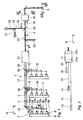
- FIG. 1 To illustrate positional relationships is the Fig. 1 and further figures associated with the drawing a Cartesian xyz coordinate system.
- the x-axis runs in the Fig. 1 up.
- the y-axis is perpendicular to the plane of the Fig. 1 towards the viewer and the z-axis runs to the right.
- a laser device 1 has a plurality of single-emitter laser diodes 2 whose individual output beams 3 are superimposed to form a total output beam 4. The generated total output beam 4 is then used with the Light coupled further laser, so that a white light beam is generated, which is then scanned for show laser purposes, for example via a projection surface 5. The laser device 1 generates the red light portion of the white light beam to be scanned.
- laser diodes having an output wavelength of 660 nm and a mean output power of 130 mW in cw mode (continuous wave) are used as single-emitter laser diodes 2.
- Fig. 6 6 shows a typical emission surface 6 of one of the single-emitter laser diodes 2.
- the emission surface 6 is approximately elliptical and has an extension of typically 1.5 ⁇ m in the x-direction and an extension of typically 1.0 ⁇ m in the y-direction.
- This expansion in the x- and y-direction in each case is associated with a typical beam divergence of the single output beam 3 of this single emitter laser diode 2.
- Each of the single emitter laser diodes 2 has immediately after the emission surface 6 a first collimator 7, which reduces the divergence of the single output beam 3 in the x-direction to about 7 mrad and in the y-direction to about 16 mrad.
- a first collimator 7 which reduces the divergence of the single output beam 3 in the x-direction to about 7 mrad and in the y-direction to about 16 mrad.
- the laser device 1 is due to these very small divergences in the x and y directions virtually no widening of the single output jets 3 available.
- the long main axis of the emission surface 6, ie the x-axis, is no longer than 1.7 ⁇ m in the single-emitter laser diodes 2 used.
- the aspect ratio of the divergences in the x and y directions is 1: 1.3 to 1: 2.5 for the single emitter laser diodes 2 used.
- This divergence ratio x / y is preferably 1: 1.5.
- single emitter laser diodes may also be used, for example a single emitter laser diode with an output wavelength of 642 nm and a cw output power of 90 mW, a divergence in the x direction of 10 mrad and in the y direction of 21 mrad.
- Typical emission areas of the single emitter laser diodes used have extents of 1 ⁇ m in the y-direction and 1.5 to 5 ⁇ m in the x-direction. Shown in the Fig. 1 a total of twelve of the single-emitter laser diodes 2, which are each arranged in three groups 8 to four of the single-emitter laser diodes 2.
- the four laser diodes 2 of a group 8 are each arranged on a common support and heat sink 9 in parallel and equidistant from each other, wherein they radiate in the positive z-direction.
- the laser diodes 2 in the Fig. 1 Group 8 shown on the left are labeled from bottom to top with 2a, 2b, 2c and 2d.
- Each of the laser diodes 2a to 2d is associated with a 90 ° deflecting mirror 10a to 10d. Selected these deflecting mirrors 10 serve to bring together the individual output beams 3 to the total output beam 4 and are therefore also referred to below as merging deflecting mirror.
- the merge serve the deflection mirror 10b to 10d.
- the deflecting mirrors 10 are arranged not only offset relative to one another in the x-direction in accordance with the x-positions of the laser diodes 2 a to 2 d, but also offset relative to one another in the z-direction. This ensures that at each of the merging deflecting mirrors 10b to 10d, a first single output beam 3 not reflected by the merging deflecting mirror 10b to 10d has at least one second, from the merging deflecting mirror 10b to 10d reflected single output beam 3 is merged.
- This situation is exemplified by the merging deflecting mirror 10b in FIG Fig. 3 shown enlarged.
- the non-reflected by Caribbean constitutional-deflecting mirror 10b single output beam 3 is in the Fig. 3 with 3a and by the merging deflection mirror 10b by 90 ° reflected single output beam 3 is in Fig. 3 designated 3b.
- the merging deflection mirror 10b is arranged such that neither the entire bundle cross section of the guided, non-reflected single output beam 3a nor the entire beam cross section of the reflected single output beam 3b is used contributing to a merged intermediate output beam 11. Rather, at the converging deflection mirror 10, a part of the non-reflected single output beam 3a and also a part of the reflected single output beam 3b are cut off, so that the cut-off cross-sectional parts do not contribute to the intermediate output beam 11. A boundary line between the used and the cut, each incident single output beam 3a, 3b and the cut portion of these individual output beams 3a, 3b is in the Fig. 3 shown at 12.
- the intensity ratios between the used and the cut portions of the single output jets 3a, 3b illustrate Fig. 5 ,
- the intensity profile of the single output beams 3 is approximately Gaussian in the single-emitter laser diodes 2. Beyond the boundary line 12, a maximum of 10% of the total bundle intensity is cut off. This means that 90% of the intensities of the individual output jets 3a and 3b are used in the intermediate output beam 11 after the merging deflection mirror 10b.
- the individual output beams 3a, 3b can thus be very narrow, with virtually no gap, with only slight losses, be led side by side.
- This quadruple output beam is then deflected by another 90 ° deflecting mirror 13, so that it subsequently propagates in the positive z-direction.
- this fourfold intermediate output beam 11 is guided past a further merging deflecting mirror 14.
- This passage is in a schematic overview in the Fig. 2 and enlarged in the Fig. 4 shown.
- the merging deflection mirror 14 again about 10% of the intensity of the passing fourfold intermediate output beam 11 is cut off.
- the corresponding boundary line 12 is in the Fig. 4 located.
- another fourfold intermediate output beam 15 is deflected by 90 ° in the xz plane by the merging deflection mirror 14, so that it then likewise propagates in the positive z direction.
- FIG Fig. 4 A truncated portion of the quadruple intermediate output beam 15, which is not reflected, is in FIG Fig. 4 shown in phantom at 16.
- the merging deflecting mirror 14 also ensures that in the beam path this merging deflecting mirror 14, the intermediate output beams 11, 15 closely adjacent to each other virtually without any gap, without losing more than 10% of the incident beam intensity. In each case, 10% of the incident intensity is also cut off from the intermediate output beams 11 and 15, so that with regard to the intensity used and the cut-off intensity, the conditions which have been mentioned above in connection with FIG Fig. 5 were explained.
- this passes through a further merging deflection mirror 18, the function of which corresponds to the merging deflection mirror 14.
- a further fourfold intermediate output beam 19 is coupled to the eightfold intermediate output beam 17 by 90 ° deflection, again 10% of the intensities of the reflected single output beams 3 and 10% of the intensities of the four directly on the convergence deflection mirror 8 passing single output jets 3 of the eight times intermediate output beam 17 are cut off.
- intermediate output beam 20 which is constructed of twelve individual output jets 3 running side by side with virtually no gap, with four individual output jets 3 next to one another in the x direction and three single output jets 3 in y Direction are arranged one above the other.
- This Twelve times the intermediate output beam 20, also referred to as a group beam array, is then narrowed by a group collimator to reduce the beam cross-section to a subsequent 1 / e beam cross-section, which is 4 to 5 mm in the illustrated embodiment. Since twelve times, ie 4x3, intermediate output beam 20 has an approximately square bundle cross section overall, the 1 / e bundle cross section indication represents the 1 / e diameter along the x or along the y direction.
- the group collimator 21 is designed in the manner of a Galilean telescope with a plano-convex lens 21a and a plano-concave lens 21b.
- the narrowed group beam array 20 is then combined via a coupling-polarizer 22 with another narrowed group beam array 23, which was also formed in a corresponding manner from the outputs of twelve single-emitter laser diodes 2.
- the only difference between the group beam arrays 20 and 23 is that the group beam array 20 is linearly polarized in the x direction and the group beam array 23 is linearly polarized in the y direction.
- the red total output beam 4 is present.
- this is combined via a dichroic coupling-in mirror 24 with an overlay beam 25 comprising a green overall output beam 26 and a blue overall output beam 27.
- the dichroic Einkoppelapt 24 is maximum permeable to red light and maximum reflective of green and blue light.
- the overlay beam 25 is generated by superposing the green total output beam 26 and the blue overall output beam 27 on another dichroic launch mirror 28.
- the dichroic Einkoppelspiegel 28 is maximum permeable to green light and blue Light maximum reflective.
- the green total output beam 26 is generated, for example, by frequency doubling of a neodymium solid-state laser.
- the blue overall output beam 27 can also be generated by a neodymium solid-state laser, which is frequency-doubled in the resonator.
- the wavelength of the green total output beam is 532 nm.
- the wavelength of the blue total output beam is 473 nm.
- a white total output beam 29 After the dichroic coupling-in mirror 24, there is a white total output beam 29 which passes through a scanner 30.
- This scanner 30 deflects the total output beam 29 in a synchronized manner, so that a desired light pattern is produced on the projection surface 5, which is spaced apart from the scanner 30 by about 10 to 20 m.
- the operation of the scanner 30 is preferably synchronized with unillustrated intensity modulators located in the beam paths of the total output beams 4, 26 and 27 and independently modulating the three primary colors red, green and blue for imaging.
- the cross section of the total output beam 4 after the scanner 30 looks approximately as in FIG Fig. 7 shown. Due to the somewhat higher divergence in the y-direction, the single output jets 3 are widened somewhat more strongly in the y-direction than in the x-direction, so that the beam diameters ⁇ y of the single output jets 3 are larger than the beam diameters ⁇ x in x perpendicular thereto -Direction. This effect is compensated by the fact that in the y direction in the total output beam 4 there are three adjacent single output jets 3, while in the x direction four adjacent single output jets 3 are present be present, so that the total output beam 4 after the scanner 30 has an approximately square envelope.
- Fig. 8 shows the total output beam 4 after further propagation by about 10 to 20 m shortly before hitting the projection surface 5.
- the representation after Fig. 8 is not to scale for illustration Fig. 7 , Due to the divergence, the individual output jets 3 are now widened more strongly, whereby adjacent single output jets 3 now penetrate.
- Fig. 9 shows a situation in which the total output beam 4 was further merged by adjusting the single output beams 3 just before the projection surface 5.
- the deflecting mirrors 10 and in particular 14 and 18 were adjusted so that the single output jets 3 in the y-direction are all approximately at a height. From the three superimposed rows of fourfold intermediate output jets, a fourfold series of single output jets 3 has become, which strongly penetrate due to the long propagation path. Energetic main beams 31 of the individual output beams 3 are combined within the overall output beam 4, that is to say in particular within the group beam arrays 20, 23, along the beam path of these group beam arrays 20, 23 by this adjustment.
- the deflection mirror 10 it is possible for the fourfold intermediate output beam after Fig. 9 to summarize even further in the x-direction.
- the bundle diameter of the total output beam is reduced in this way again, which improves the quality of the projection produced on the projection surface 5, in particular its contrast.
Landscapes
- Physics & Mathematics (AREA)
- General Physics & Mathematics (AREA)
- Optics & Photonics (AREA)
- Condensed Matter Physics & Semiconductors (AREA)
- Electromagnetism (AREA)
- Semiconductor Lasers (AREA)
- Laser Surgery Devices (AREA)
- Glass Compositions (AREA)
- Optical Radar Systems And Details Thereof (AREA)
- Optical Elements Other Than Lenses (AREA)
Applications Claiming Priority (1)
| Application Number | Priority Date | Filing Date | Title |
|---|---|---|---|
| DE102007045845A DE102007045845A1 (de) | 2007-09-26 | 2007-09-26 | Laservorrichtung |
Publications (3)
| Publication Number | Publication Date |
|---|---|
| EP2043211A2 true EP2043211A2 (fr) | 2009-04-01 |
| EP2043211A3 EP2043211A3 (fr) | 2011-02-23 |
| EP2043211B1 EP2043211B1 (fr) | 2011-10-26 |
Family
ID=40239743
Family Applications (1)
| Application Number | Title | Priority Date | Filing Date |
|---|---|---|---|
| EP08011020A Active EP2043211B1 (fr) | 2007-09-26 | 2008-06-18 | Dispositif laser |
Country Status (7)
| Country | Link |
|---|---|
| EP (1) | EP2043211B1 (fr) |
| AT (1) | ATE531106T1 (fr) |
| DE (1) | DE102007045845A1 (fr) |
| DK (1) | DK2043211T3 (fr) |
| ES (1) | ES2372883T3 (fr) |
| HR (1) | HRP20110843T1 (fr) |
| SI (1) | SI2043211T1 (fr) |
Cited By (12)
| Publication number | Priority date | Publication date | Assignee | Title |
|---|---|---|---|---|
| WO2010138190A1 (fr) * | 2009-05-28 | 2010-12-02 | Eastman Kodak Company | Système d'alignement de faisceaux utilisant des matrices de sources de lumière |
| US7959297B2 (en) | 2008-05-15 | 2011-06-14 | Eastman Kodak Company | Uniform speckle reduced laser projection using spatial and temporal mixing |
| US8066389B2 (en) | 2009-04-30 | 2011-11-29 | Eastman Kodak Company | Beam alignment chamber providing divergence correction |
| US8132919B2 (en) | 2009-04-30 | 2012-03-13 | Eastman Kodak Company | Digital projector using arrayed light sources |
| DE102012208088A1 (de) | 2011-05-25 | 2012-11-29 | LASAIR e.K. | Laservorrichtung mit einer Mehrzahl von Laserdioden sowie Verfahren zur Überlagerung von Einzel-Ausgabestrahlen mehrerer Laserdioden zu einem Gesamt-Ausgabestrahl |
| GB2511483A (en) * | 2013-01-15 | 2014-09-10 | Coolled Ltd | LED Illumination |
| EP2767859A4 (fr) * | 2011-10-11 | 2015-04-29 | Appotronics Corp Ltd | Système de source lumineuse et source lumineuse à laser |
| WO2015149877A1 (fr) * | 2014-04-04 | 2015-10-08 | Barco Nv | Système d'éclairage par projection laser |
| EP2933673A1 (fr) * | 2014-04-16 | 2015-10-21 | KVANT spol. s r.o. | Dispositif de création d'un faisceau de lumière à couleurs intenses avec une section circulaire, d'une distribution homogène de l'intensité lumineuse et d'une divergence de faisceau de 0 à 10° |
| CN105071224A (zh) * | 2015-07-28 | 2015-11-18 | 深圳市创鑫激光股份有限公司 | 一种激光器 |
| DE202014010545U1 (de) | 2014-06-17 | 2015-12-07 | Christian Marx | Laseranordnung zur Erzeugung eines Hochleistungs-Ausgabestrahls |
| CN105826816A (zh) * | 2015-01-23 | 2016-08-03 | 朗美通运营有限责任公司 | 产生光的激光二极管子组件和方法 |
Citations (1)
| Publication number | Priority date | Publication date | Assignee | Title |
|---|---|---|---|---|
| DE202005009294U1 (de) | 2005-06-13 | 2005-11-17 | Arctos Showlasertechnik E.Kfm. | Laservorrichtungen zur Erzeugung von Laserstrahlen |
Family Cites Families (4)
| Publication number | Priority date | Publication date | Assignee | Title |
|---|---|---|---|---|
| US4826269A (en) * | 1987-10-16 | 1989-05-02 | Spectra Diode Laboratories, Inc. | Diode laser arrangement forming bright image |
| JPH0260179A (ja) * | 1988-08-26 | 1990-02-28 | Fuji Photo Film Co Ltd | 合波用レーザ光源装置 |
| DE69132049T3 (de) * | 1990-08-01 | 2004-09-02 | Diomed Ltd. | Hochleistungs-lichtquelle |
| US5715270A (en) * | 1996-09-27 | 1998-02-03 | Mcdonnell Douglas Corporation | High efficiency, high power direct diode laser systems and methods therefor |
-
2007
- 2007-09-26 DE DE102007045845A patent/DE102007045845A1/de not_active Ceased
-
2008
- 2008-06-18 DK DK08011020.8T patent/DK2043211T3/da active
- 2008-06-18 SI SI200830531T patent/SI2043211T1/sl unknown
- 2008-06-18 ES ES08011020T patent/ES2372883T3/es active Active
- 2008-06-18 EP EP08011020A patent/EP2043211B1/fr active Active
- 2008-06-18 AT AT08011020T patent/ATE531106T1/de active
-
2011
- 2011-11-14 HR HR20110843T patent/HRP20110843T1/hr unknown
Patent Citations (1)
| Publication number | Priority date | Publication date | Assignee | Title |
|---|---|---|---|---|
| DE202005009294U1 (de) | 2005-06-13 | 2005-11-17 | Arctos Showlasertechnik E.Kfm. | Laservorrichtungen zur Erzeugung von Laserstrahlen |
Cited By (23)
| Publication number | Priority date | Publication date | Assignee | Title |
|---|---|---|---|---|
| US7959297B2 (en) | 2008-05-15 | 2011-06-14 | Eastman Kodak Company | Uniform speckle reduced laser projection using spatial and temporal mixing |
| US8066389B2 (en) | 2009-04-30 | 2011-11-29 | Eastman Kodak Company | Beam alignment chamber providing divergence correction |
| US8132919B2 (en) | 2009-04-30 | 2012-03-13 | Eastman Kodak Company | Digital projector using arrayed light sources |
| WO2010138190A1 (fr) * | 2009-05-28 | 2010-12-02 | Eastman Kodak Company | Système d'alignement de faisceaux utilisant des matrices de sources de lumière |
| US8033666B2 (en) | 2009-05-28 | 2011-10-11 | Eastman Kodak Company | Beam alignment system using arrayed light sources |
| JP2012528356A (ja) * | 2009-05-28 | 2012-11-12 | イーストマン コダック カンパニー | 光源アレイを備えるビーム整列システム |
| DE102012208088A1 (de) | 2011-05-25 | 2012-11-29 | LASAIR e.K. | Laservorrichtung mit einer Mehrzahl von Laserdioden sowie Verfahren zur Überlagerung von Einzel-Ausgabestrahlen mehrerer Laserdioden zu einem Gesamt-Ausgabestrahl |
| CN104868362A (zh) * | 2011-10-11 | 2015-08-26 | 深圳市光峰光电技术有限公司 | 光源系统与激光光源 |
| CN104868361A (zh) * | 2011-10-11 | 2015-08-26 | 深圳市光峰光电技术有限公司 | 光源系统与激光光源 |
| EP2767859A4 (fr) * | 2011-10-11 | 2015-04-29 | Appotronics Corp Ltd | Système de source lumineuse et source lumineuse à laser |
| US10530131B2 (en) | 2011-10-11 | 2020-01-07 | Appotronics Corporation Limited | Light source system and laser light source |
| CN104868361B (zh) * | 2011-10-11 | 2019-07-16 | 深圳光峰科技股份有限公司 | 光源系统与激光光源 |
| US9819154B2 (en) | 2011-10-11 | 2017-11-14 | Appotronics Corporation Limited | Light source system and laser light source |
| GB2511483B (en) * | 2013-01-15 | 2016-11-23 | Coolled Ltd | LED Illumination |
| GB2511483A (en) * | 2013-01-15 | 2014-09-10 | Coolled Ltd | LED Illumination |
| US9720219B2 (en) | 2013-01-15 | 2017-08-01 | Coolled Limited | LED illumination |
| WO2015149877A1 (fr) * | 2014-04-04 | 2015-10-08 | Barco Nv | Système d'éclairage par projection laser |
| US11067885B2 (en) | 2014-04-04 | 2021-07-20 | Barco Nv | Laser projection illumination system |
| EP2933673A1 (fr) * | 2014-04-16 | 2015-10-21 | KVANT spol. s r.o. | Dispositif de création d'un faisceau de lumière à couleurs intenses avec une section circulaire, d'une distribution homogène de l'intensité lumineuse et d'une divergence de faisceau de 0 à 10° |
| DE202014010545U1 (de) | 2014-06-17 | 2015-12-07 | Christian Marx | Laseranordnung zur Erzeugung eines Hochleistungs-Ausgabestrahls |
| CN105826816A (zh) * | 2015-01-23 | 2016-08-03 | 朗美通运营有限责任公司 | 产生光的激光二极管子组件和方法 |
| CN105071224B (zh) * | 2015-07-28 | 2016-09-28 | 深圳市创鑫激光股份有限公司 | 一种激光器 |
| CN105071224A (zh) * | 2015-07-28 | 2015-11-18 | 深圳市创鑫激光股份有限公司 | 一种激光器 |
Also Published As
| Publication number | Publication date |
|---|---|
| ATE531106T1 (de) | 2011-11-15 |
| HRP20110843T1 (hr) | 2011-12-31 |
| SI2043211T1 (sl) | 2012-03-30 |
| DE102007045845A1 (de) | 2009-04-09 |
| ES2372883T3 (es) | 2012-01-27 |
| EP2043211A3 (fr) | 2011-02-23 |
| DK2043211T3 (da) | 2012-02-27 |
| EP2043211B1 (fr) | 2011-10-26 |
Similar Documents
| Publication | Publication Date | Title |
|---|---|---|
| EP2043211B1 (fr) | Dispositif laser | |
| DE19939750C2 (de) | Optische Anordnung zur Verwendung bei einer Laserdiodenanordnung sowie Laserdiodenanordnung mit einer solchen optischen Anordnung | |
| DE19780124B4 (de) | Anordnung zur Formung des geometrischen Querschnitts mehrerer Festkörper- und/oder Halbleiterlaser | |
| DE19725262C2 (de) | Optische Strahltransformationsvorrichtung | |
| EP0984312B1 (fr) | Ensemble diode laser | |
| EP2973899B1 (fr) | Dispositif de couplage de longueurs d'onde de rayons laser | |
| WO2020016336A1 (fr) | Dispositif, système laser et procédé pour la combinaison de faisceaux laser cohérents | |
| DE19751106A1 (de) | Laserdrucker zum Drucken auf ein lichtempfindliches Medium | |
| WO2007140969A1 (fr) | Dispositif de mise en forme de rayon | |
| EP2217961A1 (fr) | Dispositif de mise en forme de faisceau | |
| DE10245811A1 (de) | Verfahren und Vorrichtung zum Beleuchten eines Raumlichtmodulators | |
| EP2184818A1 (fr) | Agencement de pompage laser et procédé de pompage laser doté d'une homogénéisation de rayonnement | |
| EP1145390A2 (fr) | Systeme d'amplification laser | |
| EP4281244B1 (fr) | Dispositif pour le traitement de matériaux au laser | |
| DE10148167A1 (de) | Beleuchtungsanordnung | |
| EP1617275A1 (fr) | Dispositif pour illuminer une surface comprenant une barre de diodes laser et des moyens de transformation de faisceau optique | |
| EP2508934B1 (fr) | Laser à diodes | |
| WO2020011315A1 (fr) | Optique laser formant des faisceaux | |
| WO2012032116A1 (fr) | Dispositif laser pour la production d'une répartition linéaire d'intensité dans un plan de travail | |
| DE202007019521U1 (de) | Laservorrichtung | |
| DE10062453A1 (de) | Verfahren und Vorrichtung zur Überlagerung von Strahlenbündeln | |
| DE102004040608B4 (de) | Diodenlaser mit einer optischen Einrichtung zur Erhöhung der Strahldichte eines aus ihm austretenden Ausgangslaserstrahls | |
| DE102017108936A1 (de) | Homogenisierung von Pumplaserstrahlung | |
| DE10007123A1 (de) | Optische Anordnung zur Verwendung bei einer Laserdiodenanordnung sowie Laserdiodenanordnung mit einer solchen Anordnung | |
| WO2016026523A1 (fr) | Procédé d'extension du trajet d'un faisceau de lumière, dispositif de retard optique et ensemble laser d'attaque |
Legal Events
| Date | Code | Title | Description |
|---|---|---|---|
| PUAI | Public reference made under article 153(3) epc to a published international application that has entered the european phase |
Free format text: ORIGINAL CODE: 0009012 |
|
| AK | Designated contracting states |
Kind code of ref document: A2 Designated state(s): AT BE BG CH CY CZ DE DK EE ES FI FR GB GR HR HU IE IS IT LI LT LU LV MC MT NL NO PL PT RO SE SI SK TR |
|
| AX | Request for extension of the european patent |
Extension state: AL BA MK RS |
|
| PUAL | Search report despatched |
Free format text: ORIGINAL CODE: 0009013 |
|
| AK | Designated contracting states |
Kind code of ref document: A3 Designated state(s): AT BE BG CH CY CZ DE DK EE ES FI FR GB GR HR HU IE IS IT LI LT LU LV MC MT NL NO PL PT RO SE SI SK TR |
|
| AX | Request for extension of the european patent |
Extension state: AL BA MK RS |
|
| GRAP | Despatch of communication of intention to grant a patent |
Free format text: ORIGINAL CODE: EPIDOSNIGR1 |
|
| 17P | Request for examination filed |
Effective date: 20110413 |
|
| RIC1 | Information provided on ipc code assigned before grant |
Ipc: H01S 5/40 20060101AFI20110509BHEP |
|
| RAP1 | Party data changed (applicant data changed or rights of an application transferred) |
Owner name: ARCTOS SHOWLASERTECHNIK GMBH |
|
| GRAS | Grant fee paid |
Free format text: ORIGINAL CODE: EPIDOSNIGR3 |
|
| GRAA | (expected) grant |
Free format text: ORIGINAL CODE: 0009210 |
|
| AK | Designated contracting states |
Kind code of ref document: B1 Designated state(s): AT BE BG CH CY CZ DE DK EE ES FI FR GB GR HR HU IE IS IT LI LT LU LV MC MT NL NO PL PT RO SE SI SK TR |
|
| AKX | Designation fees paid |
Designated state(s): AT BE BG CH CY CZ DE DK EE ES FI FR GB GR HR HU IE IS IT LI LT LU LV MC MT NL NO PL PT RO SE SI SK TR |
|
| REG | Reference to a national code |
Ref country code: GB Ref legal event code: FG4D Free format text: NOT ENGLISH |
|
| REG | Reference to a national code |
Ref country code: CH Ref legal event code: EP |
|
| REG | Reference to a national code |
Ref country code: HR Ref legal event code: TUEP Ref document number: P20110843 Country of ref document: HR |
|
| REG | Reference to a national code |
Ref country code: IE Ref legal event code: FG4D |
|
| REG | Reference to a national code |
Ref country code: DE Ref legal event code: R096 Ref document number: 502008005318 Country of ref document: DE Effective date: 20111222 |
|
| REG | Reference to a national code |
Ref country code: HR Ref legal event code: T1PR Ref document number: P20110843 Country of ref document: HR |
|
| REG | Reference to a national code |
Ref country code: ES Ref legal event code: FG2A Ref document number: 2372883 Country of ref document: ES Kind code of ref document: T3 Effective date: 20120127 |
|
| REG | Reference to a national code |
Ref country code: NL Ref legal event code: T3 |
|
| REG | Reference to a national code |
Ref country code: DK Ref legal event code: T3 |
|
| REG | Reference to a national code |
Ref country code: SK Ref legal event code: T3 Ref document number: E 11008 Country of ref document: SK |
|
| PG25 | Lapsed in a contracting state [announced via postgrant information from national office to epo] |
Ref country code: IS Free format text: LAPSE BECAUSE OF FAILURE TO SUBMIT A TRANSLATION OF THE DESCRIPTION OR TO PAY THE FEE WITHIN THE PRESCRIBED TIME-LIMIT Effective date: 20120226 Ref country code: NO Free format text: LAPSE BECAUSE OF FAILURE TO SUBMIT A TRANSLATION OF THE DESCRIPTION OR TO PAY THE FEE WITHIN THE PRESCRIBED TIME-LIMIT Effective date: 20120126 |
|
| PG25 | Lapsed in a contracting state [announced via postgrant information from national office to epo] |
Ref country code: PT Free format text: LAPSE BECAUSE OF FAILURE TO SUBMIT A TRANSLATION OF THE DESCRIPTION OR TO PAY THE FEE WITHIN THE PRESCRIBED TIME-LIMIT Effective date: 20120227 Ref country code: GR Free format text: LAPSE BECAUSE OF FAILURE TO SUBMIT A TRANSLATION OF THE DESCRIPTION OR TO PAY THE FEE WITHIN THE PRESCRIBED TIME-LIMIT Effective date: 20120127 Ref country code: LV Free format text: LAPSE BECAUSE OF FAILURE TO SUBMIT A TRANSLATION OF THE DESCRIPTION OR TO PAY THE FEE WITHIN THE PRESCRIBED TIME-LIMIT Effective date: 20111026 Ref country code: SE Free format text: LAPSE BECAUSE OF FAILURE TO SUBMIT A TRANSLATION OF THE DESCRIPTION OR TO PAY THE FEE WITHIN THE PRESCRIBED TIME-LIMIT Effective date: 20111026 Ref country code: PL Free format text: LAPSE BECAUSE OF FAILURE TO SUBMIT A TRANSLATION OF THE DESCRIPTION OR TO PAY THE FEE WITHIN THE PRESCRIBED TIME-LIMIT Effective date: 20111026 |
|
| REG | Reference to a national code |
Ref country code: IE Ref legal event code: FD4D |
|
| PG25 | Lapsed in a contracting state [announced via postgrant information from national office to epo] |
Ref country code: CY Free format text: LAPSE BECAUSE OF FAILURE TO SUBMIT A TRANSLATION OF THE DESCRIPTION OR TO PAY THE FEE WITHIN THE PRESCRIBED TIME-LIMIT Effective date: 20111026 |
|
| PG25 | Lapsed in a contracting state [announced via postgrant information from national office to epo] |
Ref country code: EE Free format text: LAPSE BECAUSE OF FAILURE TO SUBMIT A TRANSLATION OF THE DESCRIPTION OR TO PAY THE FEE WITHIN THE PRESCRIBED TIME-LIMIT Effective date: 20111026 Ref country code: IE Free format text: LAPSE BECAUSE OF FAILURE TO SUBMIT A TRANSLATION OF THE DESCRIPTION OR TO PAY THE FEE WITHIN THE PRESCRIBED TIME-LIMIT Effective date: 20111026 Ref country code: BG Free format text: LAPSE BECAUSE OF FAILURE TO SUBMIT A TRANSLATION OF THE DESCRIPTION OR TO PAY THE FEE WITHIN THE PRESCRIBED TIME-LIMIT Effective date: 20120126 Ref country code: CZ Free format text: LAPSE BECAUSE OF FAILURE TO SUBMIT A TRANSLATION OF THE DESCRIPTION OR TO PAY THE FEE WITHIN THE PRESCRIBED TIME-LIMIT Effective date: 20111026 |
|
| PGFP | Annual fee paid to national office [announced via postgrant information from national office to epo] |
Ref country code: LT Payment date: 20120606 Year of fee payment: 5 |
|
| PG25 | Lapsed in a contracting state [announced via postgrant information from national office to epo] |
Ref country code: RO Free format text: LAPSE BECAUSE OF FAILURE TO SUBMIT A TRANSLATION OF THE DESCRIPTION OR TO PAY THE FEE WITHIN THE PRESCRIBED TIME-LIMIT Effective date: 20111026 |
|
| PLBE | No opposition filed within time limit |
Free format text: ORIGINAL CODE: 0009261 |
|
| STAA | Information on the status of an ep patent application or granted ep patent |
Free format text: STATUS: NO OPPOSITION FILED WITHIN TIME LIMIT |
|
| 26N | No opposition filed |
Effective date: 20120727 |
|
| REG | Reference to a national code |
Ref country code: DE Ref legal event code: R097 Ref document number: 502008005318 Country of ref document: DE Effective date: 20120727 |
|
| REG | Reference to a national code |
Ref country code: HU Ref legal event code: AG4A Ref document number: E013381 Country of ref document: HU |
|
| PG25 | Lapsed in a contracting state [announced via postgrant information from national office to epo] |
Ref country code: MC Free format text: LAPSE BECAUSE OF NON-PAYMENT OF DUE FEES Effective date: 20120630 |
|
| PG25 | Lapsed in a contracting state [announced via postgrant information from national office to epo] |
Ref country code: FI Free format text: LAPSE BECAUSE OF FAILURE TO SUBMIT A TRANSLATION OF THE DESCRIPTION OR TO PAY THE FEE WITHIN THE PRESCRIBED TIME-LIMIT Effective date: 20111026 |
|
| PG25 | Lapsed in a contracting state [announced via postgrant information from national office to epo] |
Ref country code: MT Free format text: LAPSE BECAUSE OF FAILURE TO SUBMIT A TRANSLATION OF THE DESCRIPTION OR TO PAY THE FEE WITHIN THE PRESCRIBED TIME-LIMIT Effective date: 20111026 |
|
| REG | Reference to a national code |
Ref country code: LT Ref legal event code: MM4D Effective date: 20130618 |
|
| PG25 | Lapsed in a contracting state [announced via postgrant information from national office to epo] |
Ref country code: LT Free format text: LAPSE BECAUSE OF NON-PAYMENT OF DUE FEES Effective date: 20130618 |
|
| PG25 | Lapsed in a contracting state [announced via postgrant information from national office to epo] |
Ref country code: TR Free format text: LAPSE BECAUSE OF FAILURE TO SUBMIT A TRANSLATION OF THE DESCRIPTION OR TO PAY THE FEE WITHIN THE PRESCRIBED TIME-LIMIT Effective date: 20111026 |
|
| PG25 | Lapsed in a contracting state [announced via postgrant information from national office to epo] |
Ref country code: LU Free format text: LAPSE BECAUSE OF NON-PAYMENT OF DUE FEES Effective date: 20120618 |
|
| REG | Reference to a national code |
Ref country code: FR Ref legal event code: PLFP Year of fee payment: 9 |
|
| REG | Reference to a national code |
Ref country code: FR Ref legal event code: PLFP Year of fee payment: 10 |
|
| REG | Reference to a national code |
Ref country code: FR Ref legal event code: PLFP Year of fee payment: 11 |
|
| REG | Reference to a national code |
Ref country code: HR Ref legal event code: ODRP Ref document number: P20110843 Country of ref document: HR Payment date: 20190606 Year of fee payment: 12 |
|
| REG | Reference to a national code |
Ref country code: HR Ref legal event code: ODRP Ref document number: P20110843 Country of ref document: HR Payment date: 20200608 Year of fee payment: 13 |
|
| REG | Reference to a national code |
Ref country code: HR Ref legal event code: ODRP Ref document number: P20110843 Country of ref document: HR Payment date: 20210609 Year of fee payment: 14 |
|
| REG | Reference to a national code |
Ref country code: HR Ref legal event code: ODRP Ref document number: P20110843 Country of ref document: HR Payment date: 20220606 Year of fee payment: 15 |
|
| PGFP | Annual fee paid to national office [announced via postgrant information from national office to epo] |
Ref country code: HR Payment date: 20220606 Year of fee payment: 15 Ref country code: DK Payment date: 20220623 Year of fee payment: 15 |
|
| PGFP | Annual fee paid to national office [announced via postgrant information from national office to epo] |
Ref country code: BE Payment date: 20220621 Year of fee payment: 15 |
|
| PGFP | Annual fee paid to national office [announced via postgrant information from national office to epo] |
Ref country code: CH Payment date: 20220702 Year of fee payment: 15 |
|
| REG | Reference to a national code |
Ref country code: HR Ref legal event code: PBON Ref document number: P20110843 Country of ref document: HR Effective date: 20230618 |
|
| P01 | Opt-out of the competence of the unified patent court (upc) registered |
Effective date: 20231208 |
|
| REG | Reference to a national code |
Ref country code: DK Ref legal event code: EBP Effective date: 20230630 |
|
| REG | Reference to a national code |
Ref country code: CH Ref legal event code: PL |
|
| REG | Reference to a national code |
Ref country code: BE Ref legal event code: MM Effective date: 20230630 |
|
| PG25 | Lapsed in a contracting state [announced via postgrant information from national office to epo] |
Ref country code: CH Free format text: LAPSE BECAUSE OF NON-PAYMENT OF DUE FEES Effective date: 20230630 |
|
| PG25 | Lapsed in a contracting state [announced via postgrant information from national office to epo] |
Ref country code: HR Free format text: LAPSE BECAUSE OF NON-PAYMENT OF DUE FEES Effective date: 20230618 Ref country code: BE Free format text: LAPSE BECAUSE OF NON-PAYMENT OF DUE FEES Effective date: 20230630 |
|
| PGFP | Annual fee paid to national office [announced via postgrant information from national office to epo] |
Ref country code: GB Payment date: 20240620 Year of fee payment: 17 |
|
| PG25 | Lapsed in a contracting state [announced via postgrant information from national office to epo] |
Ref country code: DK Free format text: LAPSE BECAUSE OF NON-PAYMENT OF DUE FEES Effective date: 20230630 |
|
| PGFP | Annual fee paid to national office [announced via postgrant information from national office to epo] |
Ref country code: NL Payment date: 20240619 Year of fee payment: 17 |
|
| PGFP | Annual fee paid to national office [announced via postgrant information from national office to epo] |
Ref country code: SK Payment date: 20240612 Year of fee payment: 17 |
|
| PG25 | Lapsed in a contracting state [announced via postgrant information from national office to epo] |
Ref country code: DK Free format text: LAPSE BECAUSE OF NON-PAYMENT OF DUE FEES Effective date: 20230630 |
|
| PGFP | Annual fee paid to national office [announced via postgrant information from national office to epo] |
Ref country code: FR Payment date: 20240621 Year of fee payment: 17 Ref country code: SI Payment date: 20240611 Year of fee payment: 17 |
|
| PGFP | Annual fee paid to national office [announced via postgrant information from national office to epo] |
Ref country code: IT Payment date: 20240628 Year of fee payment: 17 |
|
| PGFP | Annual fee paid to national office [announced via postgrant information from national office to epo] |
Ref country code: ES Payment date: 20240718 Year of fee payment: 17 |
|
| PGFP | Annual fee paid to national office [announced via postgrant information from national office to epo] |
Ref country code: HU Payment date: 20250613 Year of fee payment: 18 |
|
| PGFP | Annual fee paid to national office [announced via postgrant information from national office to epo] |
Ref country code: AT Payment date: 20250521 Year of fee payment: 18 |
|
| PGFP | Annual fee paid to national office [announced via postgrant information from national office to epo] |
Ref country code: DE Payment date: 20250815 Year of fee payment: 18 |
|
| REG | Reference to a national code |
Ref country code: SK Ref legal event code: MM4A Ref document number: E 11008 Country of ref document: SK Effective date: 20250618 |
|
| REG | Reference to a national code |
Ref country code: NL Ref legal event code: MM Effective date: 20250701 |
|
| GBPC | Gb: european patent ceased through non-payment of renewal fee |
Effective date: 20250618 |
|
| PG25 | Lapsed in a contracting state [announced via postgrant information from national office to epo] |
Ref country code: NL Free format text: LAPSE BECAUSE OF NON-PAYMENT OF DUE FEES Effective date: 20250701 |
|
| PG25 | Lapsed in a contracting state [announced via postgrant information from national office to epo] |
Ref country code: GB Free format text: LAPSE BECAUSE OF NON-PAYMENT OF DUE FEES Effective date: 20250618 |
|
| PG25 | Lapsed in a contracting state [announced via postgrant information from national office to epo] |
Ref country code: IT Free format text: LAPSE BECAUSE OF NON-PAYMENT OF DUE FEES Effective date: 20250618 |
|
| PG25 | Lapsed in a contracting state [announced via postgrant information from national office to epo] |
Ref country code: FR Free format text: LAPSE BECAUSE OF NON-PAYMENT OF DUE FEES Effective date: 20250630 |
|
| PG25 | Lapsed in a contracting state [announced via postgrant information from national office to epo] |
Ref country code: SK Free format text: LAPSE BECAUSE OF NON-PAYMENT OF DUE FEES Effective date: 20250618 |