EP2043374A2 - Dispositif de répartition - Google Patents
Dispositif de répartition Download PDFInfo
- Publication number
- EP2043374A2 EP2043374A2 EP08105060A EP08105060A EP2043374A2 EP 2043374 A2 EP2043374 A2 EP 2043374A2 EP 08105060 A EP08105060 A EP 08105060A EP 08105060 A EP08105060 A EP 08105060A EP 2043374 A2 EP2043374 A2 EP 2043374A2
- Authority
- EP
- European Patent Office
- Prior art keywords
- lines
- connection
- incoming
- connections
- distribution device
- Prior art date
- Legal status (The legal status is an assumption and is not a legal conclusion. Google has not performed a legal analysis and makes no representation as to the accuracy of the status listed.)
- Withdrawn
Links
Images


Classifications
-
- H—ELECTRICITY
- H04—ELECTRIC COMMUNICATION TECHNIQUE
- H04Q—SELECTING
- H04Q1/00—Details of selecting apparatus or arrangements
- H04Q1/02—Constructional details
- H04Q1/14—Distribution frames
- H04Q1/142—Terminal blocks for distribution frames
Definitions
- the present invention relates to a distribution device for the fixed connection of incoming lines with outgoing lines.
- a central control device For controlling and regulating large industrial plants of different characteristics, a central control device must process large amounts of input / output signals.
- Each individual peripheral device i.
- each individual field device actuator / sensor
- each individual field device must be electrically connected at the end of a system configuration via a field cable with a firmly defined input / output of the central control device.
- Field devices are located in industrial plants at different locations.
- the individual lines of these field devices are combined in subdistributors in such a way that They are guided by means of a multi-core cable (eg 64 wires) from there to a central distribution cabinet.
- This distribution cabinet contains preinstalled feed-through terminals.
- the feed-through terminals are used both for connecting multi-core field cables and for connecting the inputs / outputs of the central control device.
- the free ends of the feed-through terminals are now electrically connected by means of a wire.
- this wire connection can be made manually or semi-automatically.
- the direct connection technology of field devices with a central control device is characterized by the fact that one does not use any additional jumpering in the distribution cabinet.
- the field cables are not connected to pre-installed feed-through terminals in the central distribution cabinet, but are connected directly to the free input of the pre-installed feed-through terminals of the central control unit. This connection is made using a wiring list. This connection technique can only be done manually.
- connection technology has hitherto been a manual activity that must be carried out after completion of the configuration. This type of jumper wiring is very time consuming. Experience shows that with this connection technology an error rate of approx. 5% is to be expected.
- the direct connection technique is a purely manual activity on site, which is also burdened with an error rate of about 5%.
- this type of connection technology was never implemented together with evaluation electronics in a cabinet.
- the field cables can only be connected to the through terminals of the evaluation electronics after the end of the configuration.
- this also means that the field cables can only be laid in the cabinets configured for this at the end of the configuration.
- This connection technique also enforces a sequential sequence of operations. This has the consequence that the project duration is extended.
- the object of the present invention is therefore to provide a distributor device which fulfills the above-mentioned requirements.
- the actual shunting unit the shunting module, is separated from the other components of the distributor device.
- the cable laying on site can take place parallel to the configuration.
- the jumper modules After the jumper modules have been wired, they are installed on site in a dedicated shunting cabinet and connected to the already installed cables.
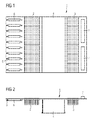
- Shunting module 1 shown incoming lines, which connect a central control device to the distribution device to be connected to each other with outgoing lines which connect a plurality of peripheral devices to the distribution device according to a predetermined scheme.
- the shunting module 1 consists essentially of two Wrapfeldern 2 and 3.
- the Wrapfeld 2 is provided for coming from the central control device lines and the Wrapfeld 3 is provided for the outgoing to the peripheral devices lines.
- Rangiermoduls 1 All parts of the Rangiermoduls 1 are arranged on a printed circuit board 5, as well as the sockets 6 for multi-pin connectors and the male connectors. 7
- the individual contacts of the sockets 6 and the male connector 7 are each 1: 1 connected to the spines of the Wrapfeldes 2 and the spines of the Wrapfeldes 3.
- the sockets 6 serve to receive high-pole connectors which terminate the lines 14 arriving from the central control device.
- the male connectors 7 are used to receive female connectors 19, which are parts of a connection module 12 to be described later and which are connected to the outgoing lines 15 to the peripheral devices.
- FIGS. 3 and 4 show a complete Rangierverteilerussi 8. This consists in the illustrated embodiment of eight superposed Rangiermodulen 1, which are mounted on a mounting bracket 9.
- the individual Rangiermodule 1 are mounted on the mounting bracket 9 such that they are mounted without play in the X and Y directions. In the Z direction, each shunting module 1 must have a clearance of approx. 6 mm. This game is the prerequisite that the contacting of the cables coming from the peripheral devices in the patch box can be carried out on site.
- This jumper distribution unit 8 must be mounted without clearance for fully automatic wiring. This can e.g. can be achieved by centering mandrels.
- FIGS. 5 and 6 shown cabinet provided.
- FIGS. 5 and 6 show the cabinet without the Rangierverteilerritt 8.
- a mounting plate 11 is provided, on which the Rangierverteilerritt 8 and the connection modules 12 described below are attached.
- the cabinet 10 are supplied by the control device incoming lines 14 with terminal plugs and the outgoing to the peripheral devices lines 15.
- the ends of the outgoing to the peripheral devices lines 15 are each connected to spring terminals 20 of the connection module 12.
- connection module 12 consists of a printed circuit board 21, on which the spring strips 19 and the individual spring-loaded terminals 20 are mounted. About not shown interconnects of the circuit board 21, the spring-loaded terminals 20 are each 1: 1 connected to the individual springs of the spring strips 19.
- the cables 14 coming from the central control device are mobile cables which are terminated with a high-pole plug-in device.
- the shunting distributor unit 8 is now firmly connected to the mounting plate 16 of the cabinet 10.
- FIGS. 7 and 8 show the marshalling cabinet 10 with a built marshalling unit 8.
- the shunting distributor unit 8 is placed with its mounting bracket 9 in a receiving device of the mounting plate 16 in the marshalling 10.
- This receiving device fixes the Rangierverteilerritt 8 in the X and Y direction in the marshalling 10 and makes an exact Ichbezug to the connection modules 12 ago.
- the jumper distribution unit 8 in the vertical position pivoted and mechanically fixed to the mounting plate 16 of the cabinet 10, for example by means of screw.
- the individual transfer connectors, ie the male connectors 7 of the Rangiermodule 1 exactly aligned in front of the transfer connectors, ie the spring strips 19 of the connection modules 12. With manual pressure in the Z direction, the transfer connectors can now be fixed together so that no relative movement is formed in the contact pairings.
Landscapes
- Engineering & Computer Science (AREA)
- Computer Networks & Wireless Communication (AREA)
- Structure Of Telephone Exchanges (AREA)
- Connections Arranged To Contact A Plurality Of Conductors (AREA)
- Patch Boards (AREA)
Applications Claiming Priority (1)
| Application Number | Priority Date | Filing Date | Title |
|---|---|---|---|
| DE200710046433 DE102007046433A1 (de) | 2007-09-28 | 2007-09-28 | Verteilereinrichtung |
Publications (2)
| Publication Number | Publication Date |
|---|---|
| EP2043374A2 true EP2043374A2 (fr) | 2009-04-01 |
| EP2043374A3 EP2043374A3 (fr) | 2010-10-27 |
Family
ID=40263305
Family Applications (1)
| Application Number | Title | Priority Date | Filing Date |
|---|---|---|---|
| EP08105060A Withdrawn EP2043374A3 (fr) | 2007-09-28 | 2008-08-18 | Dispositif de répartition |
Country Status (3)
| Country | Link |
|---|---|
| EP (1) | EP2043374A3 (fr) |
| DE (1) | DE102007046433A1 (fr) |
| ZA (1) | ZA200807710B (fr) |
Cited By (3)
| Publication number | Priority date | Publication date | Assignee | Title |
|---|---|---|---|---|
| DE102010038896A1 (de) | 2010-08-04 | 2012-02-09 | Siemens Aktiengesellschaft | Verfahren zum Testen der Automatisierungsfunktionen einer Anlage und entsprechendes Automatisierungssystem |
| DE102011081807B3 (de) * | 2011-08-30 | 2013-01-17 | Siemens Aktiengesellschaft | Verteilerschrank für ein Automatisierungssystem |
| CN104731038A (zh) * | 2013-12-23 | 2015-06-24 | 上海西门子工业自动化有限公司 | 基于comos的过程控制系统机柜设计开发系统及开发方法 |
Families Citing this family (1)
| Publication number | Priority date | Publication date | Assignee | Title |
|---|---|---|---|---|
| DE102009051314B4 (de) * | 2009-10-30 | 2012-01-12 | Adc Gmbh | Verteilereinrichtung für die Telekommunikations- und Datentechnik |
Family Cites Families (8)
| Publication number | Priority date | Publication date | Assignee | Title |
|---|---|---|---|---|
| DE1159036B (de) * | 1962-03-21 | 1963-12-12 | Siemens Ag | Rangierfeld, insbesondere fuer elektronische Umwerter in Fernsprechanlagen |
| US4603377A (en) * | 1983-10-24 | 1986-07-29 | Nec Corporation | Main distributing frame board for an electronic switching system |
| DE4042240C2 (de) * | 1990-12-31 | 1994-12-15 | Quante Ag | Anschlußmodul für eine Verteilereinrichtung, insbesondere für den Hauptverteiler von Fernmeldeeinrichtungen |
| DE9306052U1 (de) * | 1993-04-21 | 1993-06-17 | Siemens AG, 80333 München | Anordnung für die Komponenten einer Aufzugsteuerung innerhalb eines Schaltschrankes |
| CZ262396A3 (en) * | 1995-09-21 | 1997-04-16 | Reichle & De Massari Fa | Module multiple terminal strip for cable connections of telephone and data lines main switchboard |
| DE10231039A1 (de) * | 2002-07-09 | 2004-01-22 | CCS Technology, Inc., Wilmington | Verteilersystem einer Telekommunikationsanlage |
| DE10355017B4 (de) * | 2003-11-25 | 2007-05-24 | Adc Gmbh | Verteilereinrichtung für die Kommunikations- und Datentechnik |
| DE202005010160U1 (de) * | 2005-06-27 | 2005-10-27 | CCS Technology, Inc., Wilmington | Verteilereinrichtung einer Telekommunikationsanlage |
-
2007
- 2007-09-28 DE DE200710046433 patent/DE102007046433A1/de not_active Withdrawn
-
2008
- 2008-08-18 EP EP08105060A patent/EP2043374A3/fr not_active Withdrawn
- 2008-09-08 ZA ZA200807710A patent/ZA200807710B/en unknown
Cited By (5)
| Publication number | Priority date | Publication date | Assignee | Title |
|---|---|---|---|---|
| DE102010038896A1 (de) | 2010-08-04 | 2012-02-09 | Siemens Aktiengesellschaft | Verfahren zum Testen der Automatisierungsfunktionen einer Anlage und entsprechendes Automatisierungssystem |
| DE102011081807B3 (de) * | 2011-08-30 | 2013-01-17 | Siemens Aktiengesellschaft | Verteilerschrank für ein Automatisierungssystem |
| WO2013029948A1 (fr) | 2011-08-30 | 2013-03-07 | Siemens Aktiengesellschaft | Armoire de distribution pour un système d'automatisation |
| CN104731038A (zh) * | 2013-12-23 | 2015-06-24 | 上海西门子工业自动化有限公司 | 基于comos的过程控制系统机柜设计开发系统及开发方法 |
| CN104731038B (zh) * | 2013-12-23 | 2017-10-13 | 西门子工厂自动化工程有限公司 | 基于comos的过程控制系统机柜设计开发系统及开发方法 |
Also Published As
| Publication number | Publication date |
|---|---|
| DE102007046433A1 (de) | 2009-04-23 |
| ZA200807710B (en) | 2009-10-28 |
| EP2043374A3 (fr) | 2010-10-27 |
Similar Documents
| Publication | Publication Date | Title |
|---|---|---|
| EP2351154B1 (fr) | Agencement de bornes en série avec raccordements transversaux et connecteurs d'essai | |
| EP2023705A1 (fr) | Plaque d'adaptation, connecteur femelle et dispositif de liaison d'une commande électronique dotée de sa conduite de raccordement | |
| DE202007011113U1 (de) | Verdrahtungsleiterplatte | |
| EP2710619B1 (fr) | Câblage de système pour ensemble multi-relais | |
| DE2241738B2 (de) | Rangierverteiler für Alarmanlagen | |
| DE102017111245A1 (de) | Stromverteiler | |
| DE102007046433A1 (de) | Verteilereinrichtung | |
| DE202006006659U1 (de) | Elektrisches oder elektronisches Gerät | |
| EP1039589A1 (fr) | Distributeur pour connecter des actionneurs et/ou des detecteurs | |
| DE102008025433B4 (de) | Klemmenanschlußblock | |
| DE102012020219B4 (de) | Vorrichtung zum Kontaktieren von elektrischen Leitern und/oder elektrischen Kontaktelementen, sowie Leuchte oder elektrisches Gerät | |
| EP2251945B1 (fr) | Système de rails conducteurs et de connecteurs | |
| DE2722736C2 (de) | Mehrpolige Anschlußleiste | |
| DE2417285C2 (de) | Gestell zur Aufnahme von elektrischen oder elektronischen Schaltungen | |
| EP0262325A2 (fr) | Dispositif pour distributeur | |
| EP0667650A2 (fr) | Système de connexion modulaire | |
| DE202018106823U1 (de) | Busfähiges aneinanderreihbares Funktionsmodul | |
| EP3923417B1 (fr) | Boîte de dérivation | |
| EP1850159A2 (fr) | Connecteur à fiches pour un câble, câble doté d'un connecteur à fiches et procédé de raccordement d'un câble à un connecteur à fiches | |
| DE2340773A1 (de) | Uebergabesteckverbindung | |
| EP3993190A1 (fr) | Agencement de bus à rail de support avec adressage automatique de bus | |
| EP1365478B1 (fr) | Module aligné et module adaptateur | |
| EP1100152A2 (fr) | Dispositif et système de distribution | |
| DE19646107B4 (de) | Kontaktierungsanordnung für mehradrige Flachkabel | |
| DE2643046C3 (de) | Zwiscnenverteiler für Fernmeldevennittlungsanlagen |
Legal Events
| Date | Code | Title | Description |
|---|---|---|---|
| PUAI | Public reference made under article 153(3) epc to a published international application that has entered the european phase |
Free format text: ORIGINAL CODE: 0009012 |
|
| AK | Designated contracting states |
Kind code of ref document: A2 Designated state(s): AT BE BG CH CY CZ DE DK EE ES FI FR GB GR HR HU IE IS IT LI LT LU LV MC MT NL NO PL PT RO SE SI SK TR |
|
| AX | Request for extension of the european patent |
Extension state: AL BA MK RS |
|
| PUAL | Search report despatched |
Free format text: ORIGINAL CODE: 0009013 |
|
| AK | Designated contracting states |
Kind code of ref document: A3 Designated state(s): AT BE BG CH CY CZ DE DK EE ES FI FR GB GR HR HU IE IS IT LI LT LU LV MC MT NL NO PL PT RO SE SI SK TR |
|
| AX | Request for extension of the european patent |
Extension state: AL BA MK RS |
|
| 17P | Request for examination filed |
Effective date: 20110418 |
|
| AKX | Designation fees paid |
Designated state(s): AT BE BG CH CY CZ DE DK EE ES FI FR GB GR HR HU IE IS IT LI LT LU LV MC MT NL NO PL PT RO SE SI SK TR |
|
| RAP1 | Party data changed (applicant data changed or rights of an application transferred) |
Owner name: SIEMENS AKTIENGESELLSCHAFT |
|
| 17Q | First examination report despatched |
Effective date: 20140411 |
|
| STAA | Information on the status of an ep patent application or granted ep patent |
Free format text: STATUS: THE APPLICATION IS DEEMED TO BE WITHDRAWN |
|
| 18D | Application deemed to be withdrawn |
Effective date: 20160301 |