EP2043884B1 - Ensemble de commande d'une installation de chauffage et/ou de climatisation pour véhicules sur rails - Google Patents
Ensemble de commande d'une installation de chauffage et/ou de climatisation pour véhicules sur rails Download PDFInfo
- Publication number
- EP2043884B1 EP2043884B1 EP07801452A EP07801452A EP2043884B1 EP 2043884 B1 EP2043884 B1 EP 2043884B1 EP 07801452 A EP07801452 A EP 07801452A EP 07801452 A EP07801452 A EP 07801452A EP 2043884 B1 EP2043884 B1 EP 2043884B1
- Authority
- EP
- European Patent Office
- Prior art keywords
- signals
- bus
- air conditioning
- heating
- display
- Prior art date
- Legal status (The legal status is an assumption and is not a legal conclusion. Google has not performed a legal analysis and makes no representation as to the accuracy of the status listed.)
- Active
Links
Images

Classifications
-
- B—PERFORMING OPERATIONS; TRANSPORTING
- B61—RAILWAYS
- B61D—BODY DETAILS OR KINDS OF RAILWAY VEHICLES
- B61D27/00—Heating, cooling, ventilating, or air-conditioning
-
- B—PERFORMING OPERATIONS; TRANSPORTING
- B60—VEHICLES IN GENERAL
- B60H—ARRANGEMENTS OF HEATING, COOLING, VENTILATING OR OTHER AIR-TREATING DEVICES SPECIALLY ADAPTED FOR PASSENGER OR GOODS SPACES OF VEHICLES
- B60H1/00—Heating, cooling or ventilating devices
- B60H1/00642—Control systems or circuits; Control members or indication devices for heating, cooling or ventilating devices
-
- B—PERFORMING OPERATIONS; TRANSPORTING
- B61—RAILWAYS
- B61L—GUIDING RAILWAY TRAFFIC; ENSURING THE SAFETY OF RAILWAY TRAFFIC
- B61L15/00—Indicators provided on the vehicle or train for signalling purposes
- B61L15/0018—Communication with or on the vehicle or train
- B61L15/0036—Conductor-based, e.g. using CAN-Bus, train-line or optical fibres
Definitions
- the invention relates to an arrangement for operating a heating and / or air conditioning of a rail vehicle or rail vehicle train.
- the invention further relates to a rail vehicle or rail vehicle train with such an arrangement.
- An air conditioning system is also understood to mean an installation with which the air pressure in the interior of rail vehicles can be adjusted.
- Driver's cabs for rail vehicles or train sets have a large number of operating and display elements which the vehicle driver must observe or operate. Including z. B. elements for the operation of facilities such as door control, train control, vehicle drive control, vehicle brake and / or vehicle power supply. In addition to these essential for the operation of the rail vehicle or train set facilities, however, there are also facilities that serve the comfort of the driver. These include heating and / or air conditioning systems for the driver's compartment.
- the US 2002/0145516 A1 describes a system that includes at least one sensor for detecting a presence of a person in a vehicle.
- the DE 19702957 A1 describes a display device for optically displaying information display elements in different colors.
- FIG. 1 is a front view of a front panel of a control unit for a car air conditioner described.
- the front panel has a plurality of control buttons, by means of which set different operating conditions and operating parameters of the automotive air conditioning to let. Further, two recesses are provided in the front panel, behind which is the display surface of a display device.
- the front panel is located in the opening of a housing in which various electronic assemblies for the control of the air conditioning are housed.
- On the rear side of the front panel is a printed circuit board to which a flat cable is connected.
- the circuit board has a plurality of light sources, which serve the backlighting of the control buttons.
- the DE 3609098 A1 describes a vehicle heating system in which a plurality of functionally cooperating and interconnected electrical and / or electronic components are connected via bus lines that allow signal exchange. This should simplify the wiring in vehicle heating systems.
- the GB 2361074 A discloses a control system for an air conditioner, especially for automobiles.
- the control system has an input unit that includes input means for users and a storage device. Further, the control system has a control module unit connected to the input unit.
- the control module includes means for reading the data stored on the memory means and means for issuing instructions to operate one or more output means in response to the control inputs via the input means.
- a communication bus is provided, which is designed as a parallel bus.
- the signals transmitted by the driver of the display units via the bus are not further converted but can be directly received by the display units.
- the signals generated by the input elements operated by the user are transmitted via the bus to the digital input unit.
- the signal converter is designed so that it can be connected to a digital bus, in particular a serial bus (eg CAN bus). During operation of the signal converter, this digital bus signals, which are transmitted via the bus, converts into display signals, with which the display elements are controlled. In addition, the signal converter converts operating signals generated by the operating elements into the bus signals.
- the signal converter has a corresponding interface via which it can be connected to the bus.
- each of the operating elements can be assigned at least one electrical component which generates the actual operating signal when a corresponding contact is closed.
- the contact or switch itself does not necessarily have to be preassembled (even if this is preferred).
- the electrical component has already been preassembled and is connected to the signal converter via a corresponding or a plurality of corresponding electrical connections.
- an associated electrical component has been pre-assembled and has been connected to the signal converter via one or more corresponding electrical connections.
- the term electrical component includes electronic components, in particular microelectronic components.
- test computer simulates the function of a computer for the actual operation of the rail vehicle or the train and can run test programs with which all operating and display functions can be tested.
- a tester can simulate operator operation so that it can automatically check to see if the indicator is working properly.
- detectors can be used to automatically detect the displays.
- the operation and checking of the display functions during the functional check before the final assembly can also be carried out by hand.
- the signal converter (which can also be referred to as a bus coupler) can form a structural unit with the aforementioned electrical components of the display elements and controls in a particular embodiment, so that the final assembly is further facilitated.
- Such a structural unit may, in a particularly preferred embodiment, form a surface which, after installation in the guide table (i.e., after final assembly) forms part of the surface of the guide table.
- the operating elements and display elements can be arranged in the surface of the unit and / or viewed through the surface.
- the surface of the unit may be formed by a (preferably transparent or transparent) cover sheet of a membrane keypad which covers at least a portion of the display elements and controls and preferably covers all of these elements, such that the elements are protected against external influences such as theft. As moisture, dirt and harmful substances are protected.
- the structural unit may also contain the signal converter, which converts at least all signals for or from the arranged in the unit display elements and controls.
- the structural unit does not have a signal converter for connection to a bus
- the structural unit can also be equipped with a computer (for example via a multi-core cable or a wiring harness) with a computer (see below, in particular the master computer) of the Rail vehicle or the locomotive to be connected.
- a circuit board which carries a plurality of electrical components and preferably carries all the electrical components of the display elements and controls that are required for the operation of the heating and / or air conditioning in the driver's desk.
- the fully assembled arrangement (after the final assembly and preferably already after the pre-assembly) has a plurality of electrical connections (in particular printed conductors on the board) to Transmission of the control signals and the display signals, via which the circuit board (and more generally formulated a structural unit) is connected to the signal converter on the circuit board.
- the signal converter is arranged on the same board as the components. However, if the space on the board is not sufficient, for example, a second board may be provided, on which the signal converter is arranged. In this case, the two boards z. B. be electrically connected to each other via cable.
- the computer After the final assembly of the signal converter is connected via the bus with a computer for performing computing tasks for operation of the heating and / or air conditioning and for generating control signals for adjusting the heating and / or air conditioning, wherein the computer has an interface for transmitting the Has control signals to the heating and / or air conditioning.
- the computer performs control functions during operation of the system, for example the regulation of the temperature in the driver's compartment as a function of temperature measured values.
- the signal converter and / or one or more of the electrical components of the display and control elements are connected to a power supply during final assembly.
- the electrical connection between the signal converter and the electrical components can be produced, for example, via one or more plug connections and corresponding single- or multi-core cables. It is advantageous if the electrical components are carried by a single structural unit (eg the printed circuit board).
- the complex individual assembly of long electrical lines can be omitted from the controls and indicators to the control of the heating and / or air conditioning. Rather, the transmission of the signals as described can be done via the bus. This allows the signal converter, which was as described, preferably already pre-assembled and therefore can be arranged in the final assembly without much effort in or on the driver's desk.
- the computer is a central control computer of the rail vehicle or train, which also performs other functions for the operation of other facilities of the rail vehicle or train, such as Door control, vehicle diagnosis, automatic driving / braking control, SiFa (safety driving circuit) and / or voice output to the driver.
- the same bus that transmits the digital signals for the operation of the heating and / or air conditioning and the transmission of digital signals for the operation and / or status display of said other functions.
- the space required at the guide table for connecting display and control elements is thereby reduced. It can therefore be achieved a very compact and clear arrangement of all display and controls in the guide table.
- the display and controls for the heating and / or air conditioning in a clear place eg. B. are arranged on the edge of the driver's desk. They can thus lie in the immediate field of vision of the driver. In contrast, these elements were often not found in the plate or desk surface of the driver's desk.
- the signal converter is also used for the operation of the other functions and converts the corresponding digital bus signals for the operation of the other functions in display signals with which corresponding display elements are driven, and / or converts the generated by the controls for the operation of other functions Operating signals in the bus signals to. It is thus not necessary (though possible) to use more than one signal converter.
- a second signal converter and a second bus can be provided, via which the second signal converter with the master computer is connected or connected to a redundant host computer.
- a redundant host computer preferably only one of the buses for the signals of the heating and / or air conditioning is used.
- Fig. 1 schematically shows the signal-technical interconnection of display and controls that can be arranged in a driver's desk.
- a plurality of display elements 7, 8 and a plurality of controls 3, 5 are used to control and check the operating condition of a heating and / or air conditioning of the rail vehicle or units of a train. Shown in Fig. 1 two display elements and two controls. In general, however, concrete embodiments will have more controls and display elements. In particular, the controls can also perform display functions, eg. For example, indicate which operator action has been performed. However, you can also display not only the desired but also the achieved operating state of an assigned device. This is not only true for the basis of Fig. 1 explained embodiment and not only for controls a heating and / or air conditioning.
- the target temperature is set in the cab.
- the actual temperature in the cab is represented by the display element 5, for example.
- An equally related to the same physical size pair of elements are the control element 5 and the display element 8, the z. B. are related to a different adjustable temperature or humidity.
- control and display elements can be part of a device-technical unit that is pre-assembled. But it can also only parts of Operating elements and display elements to be combined into device-technical units.
- An operating element or display element is also understood to mean the combination of a visible part or a part of the element which is accessible to the operator and of at least one further part of the element which is required for the function of the visible or accessible part.
- display elements it is possible, for example, to use an electronic component which activates another component with an indication signal, so that the other component displays something in accordance with the indication signal.
- the visible part of a display element may be a lighting element or a display (this does not only apply to the case described here that the part of the element that is visible or accessible to the driver is locally separated from another part of the element).
- the display signal may then be an electrical current that lights up the luminous element or complex digital signals or signal sequences that produce a corresponding visual representation on the display.
- an electronic component which has a signal output for outputting the indication signal, which has a signal input via which it can be activated, and which is connected to a power supply.
- a signal output for outputting the indication signal
- a signal input via which it can be activated
- a power supply for the control of displays corresponding electrical and / or electronic circuits are known which generate the display signals.
- Control elements have, for example, as elements accessible for the operation elements with a touch-sensitive surface (which can be part of a touch-sensitive display, for example, or can be provided independently of a display), buttons and / or switches.
- a signal is generated by the operation of the control panel, which is supplied to the not directly accessible for the operation part of the control element.
- the operating elements and display elements each form a structural unit or a component which is in one piece and therefore can be mounted in a simple manner.
- FIG. Fig. 1 In the embodiment shown in FIG Fig. 1 is shown, all the display elements and all controls are combined into a device-technical unit 1, which can for example be pre-assembled and therefore can be easily installed in a driver's desk.
- the wording "all" refers here only to the Heating and / or air conditioning. Further operating and display elements for other devices may be provided additionally and / or as parts of other units.
- Fig. 1 are in addition to the unit 1, which has the controls and indicators for the heating and / or air conditioning, further integratable in the guide table units 2a and 2b, each operating and / or display elements for the operation of other facilities, such.
- a circuit board 13 is provided, on which the operating elements 3, 5 and the display elements 7, 8 are arranged (that is fastened and electrically connected).
- the representation of Fig. 1 is to be understood schematically.
- the unit 1 also shows the view of the controls and display elements as offered to the driver.
- elements or components 11 a, 11 b, 11 c and 11 d are shown, which are arranged directly on the printed circuit board 13.
- the components, 11a, 11b, 11c and 11d may be those parts of the controls and display elements that are not directly accessible to the vehicle operators, if the elements are not configured in one piece.
- the control element 5 which is connected via a signal line 9b with a component 11b on the circuit board 13.
- Components 11 c, 11 d are in this case connected via signal lines 9 c and 9 d to the visible parts of the display elements 8 and 7 for the driver.
- the controls and indicators are preferably each a structural unit.
- the lines 9a to 9d are then only to be understood as logical associations.
- the components 11a-11d are then identical to the display elements 7, 8 or the operating elements 3, 5.
- the components 11a-11d which are supported by the printed circuit board 13, are each connected to a signal converter 15 via signal lines 14a-14d. Via the signal lines 14c, 14d, the drive signals for driving the components 11c, 11d are transmitted from the signal converter 15 to these components 11c, 11d. About the Signal lines 14a, 14b, the signals generated by the components 11a, 11b of the controls 3, 5 are transmitted to the signal converter 15.
- the signal converter 15 is connected to a serial bus 16 for the transmission of digital signals.
- At least one central control computer 17 of the rail vehicle or rail vehicle association is connected to the bus 16.
- a part of the signal lines 14a - 14d may be connected to a plurality of signal transducers, the z. B. in turn are each connected via separate bus connections to the central control computer 17.
- the control computer 17 is connected via control lines and / or state detection lines 31 to the heating and / or air conditioning 18.
- these line connections between the host computer 31 and the system 18 can also be realized in whole or in part via the bus 16. In this case, therefore, the system 18 is connected to the bus 16.
- Conditions of the system 18 are detected via the state detection lines, such as, for example, one or more temperatures of passenger compartments, humidity values of the passenger compartments and / or pressure values of the air pressure within the passenger compartments.
- the system 18 is controlled by the host computer 17 and set in this way, for example, the temperature, pressure and / or humidity.
- the host computer software and / or hardware are implemented by the appropriate regulations of temperature, pressure and / or humidity.
- the desired temperature, the desired pressure and / or the desired humidity is predetermined by operation of the operating elements 3, 5 for the regulation or control of the system 18.
- a corresponding operating signal is transmitted to the signal converter 15 via the signal line 14a.
- This converts the signal into a signal which is transmitted in accordance with the agreed transfer protocol of the bus 16 via this to the master computer 17. From the master computer 17, the bus signals are received and made available to the implemented control.
- a door control 28 is representative of such facilities.
- the visible to the driver or directly accessible parts of these elements signal technology via signal lines 19a, 19b (in particular tracks) with no closer shown components on a circuit board 12, wherein both the elements and the components are arranged on the circuit board 12.
- the operating and display elements realized in this way are connected via signal lines 24a, 24b to the signal converter 15 or alternatively to another signal converter which is connected to the bus 16 or another bus.
- the driver specifies, for example, via the actuation of a corresponding control element in unit 2a, that the outer doors in passenger carriages are to be automatically closed.
- This operating signal passes via the signal connection chain described above to the control computer 17, which controls the actual door control 28 accordingly.
- the door controller 28 then starts the prescribed cycle to close the doors.
- a corresponding feedback signal is transmitted via the host 17, the bus 16, the signal converter 15 and the signal lines 24a or 24b to the display elements of the door control and visibly displayed for the driver.
- Fig. 1 shows that the circuit board 12 is also connected to another unit 2b, which has control and display elements for a further device, such as a driving brake control for controlling the driving and braking operation of the rail vehicle.
- the printed circuit board may have a signal converter arranged thereon for connection to the bus. Alternatively or additionally, at least a part of the elements arranged on the printed circuit board can be connected to the bus via a signal converter, which is not located on the printed circuit board.
- control and display elements By combining the control and display elements to common modules, in particular with a common printed circuit board or other supporting unit for supporting parts of the display and controls a pre-assembly and checking the pre-assembled modules before final assembly are possible.
- a common printed circuit board or other supporting unit for supporting parts of the display and controls a pre-assembly and checking the pre-assembled modules before final assembly are possible.
- the same signal converter and / or the same bus for transmitting digital signals for the operation of the heating and / or air conditioning and other facilities is used.
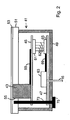
- FIG. 2 Now, another preferred aspect of the present invention will be described, namely the integration of the controls and display elements for the operation of the heating and / or air conditioning in a preassembled structural unit 41, which are those already in connection with Fig. 1 mentioned engineering unit can act.
- the unit 41 can therefore have all the controls and display elements of the heating and / or air conditioning, although in the schematic representation of Fig. 2 only one of the elements (reference numeral 43) can be seen.
- the unit 41 has a housing 49 (eg made of aluminum sheet), which defines an open-topped interior. The interior is closed at the top by a front panel 51. After final assembly, the front panel 51 forms part of the guide table.
- the front plate 51 has on its surface a film 53.
- each one of the controls and display elements shown here as an example: element 43
- element 43 is introduced, so that the transparent or transparent film 53 covers the element 43, but (im Case of a display element) can recognize the display or (in the case of a control element) allows operation of the element 43 through the flexible film 53 therethrough.
- the elements 43 are arranged on a printed circuit board 45 and connected via printed conductors 59 of the printed circuit board 45 to an electrical connection 61 (for example an electrical plug connector or a socket) of the printed circuit board 45.
- an electrical connection 61 for example an electrical plug connector or a socket
- a second printed circuit board 47 is provided, on which the signal converter 63 is arranged.
- the signal converter 63 may also be arranged on the same printed circuit board 45 as the elements 43 and in this case be electrically connected to the elements 43 via printed conductors.
- the electrical connection is made via the electrical connection 61, a further electrical connection 65, a line connection (represented by four lines 62) between the two connections 61, 65 and conductor tracks 69 on the printed circuit board 47.
- Bus 16 which includes signal converter 63, is also in Fig. 2 denoted by the reference numeral 16.
- fasteners eg, a threaded rod 73 riveted into the front panel 51
- fasteners eg, a threaded rod 73 riveted into the front panel 51
- the one or more fasteners extend z. B. through holes in the housing 49 and in or in the circuit boards therethrough. Spacers and / or nuts (eg 75) may additionally be provided for fixing the printed circuit boards.
Landscapes
- Engineering & Computer Science (AREA)
- Mechanical Engineering (AREA)
- Physics & Mathematics (AREA)
- Thermal Sciences (AREA)
- Air-Conditioning For Vehicles (AREA)
- Electric Propulsion And Braking For Vehicles (AREA)
Claims (5)
- Ensemble servant à commander une installation de chauffage et/ou de climatisation (18) d'un véhicule ferroviaire ou d'un convoi de véhicules ferroviaire, sachant que l'ensemble présente les éléments suivantes :- des éléments de commande (3, 5) de l'installation de chauffage et/ou de climatisation (18),- des éléments d'affichage (7, 8) configurés pour afficher l'état de l'installation de chauffage et/ou de climatisation (18),- un ordinateur (17) configuré pour réaliser des opérations de calcul pour un fonctionnement de l'installation de chauffage et/ou de climatisation (18) et pour générer des signaux de réglage servant à régler l'installation de chauffage et/ou de climatisation (18), sachant que l'ordinateur (17) présente une interface servant à transférer des signaux de réglage à l'installation de chauffage et/ou de climatisation (18),- un bus (16), en particulier un bus en série, configuré pour transférer des signaux de bus numériques par et vers l'ordinateur (17) et relié à l'ordinateur (17),- un convertisseur de signal (15) configuré pour convertir des signaux de bus numériques, qui sont transférés par l'intermédiaire du bus, en des signaux d'affichage, lesquels permettent de commander les éléments d'affichage (7, 8), et pour convertir des signaux de commande, lesquels sont générés par les éléments de commande (3, 5), en des signaux de bus, sachant que le convertisseur de signal (15) est raccordé au bus (16),sachant que les éléments d'affichage (7, 8) et les éléments de commande (3, 5) forment respectivement un composant électrique (11a-11d) qui génère un relevé ou génère de manière à correspondre à une action de commande le signal de commande, sachant qu'une seule unité de construction (13) est prévue, laquelle supporte une pluralité et de préférence tous les composants (11a-11d) électriques associés des éléments d'affichage (7, 8) et des éléments de commande (3, 5) de l'installation de chauffage et/ou de climatisation (18), et sachant que l'unité de construction (13) est reliée au convertisseur de signal (15) par l'intermédiaire de plusieurs liaisons électriques (14a-14d) servant à transférer les signaux de commande et les signaux d'affichage ou supporte ledit convertisseur de signal.
- Ensemble selon la revendication précédente, sachant que l'ordinateur (17) est un ordinateur pilote central qui exécute d'autres fonctions pour le fonctionnement d'autres dispositifs (28) du véhicule ferroviaire ou du convoi de véhicules ferroviaires, telles que la commande des portes, la protection du train, la commande d'entraînement des voitures, le freinage des voitures et/ou l'alimentation en courant des voitures, et sachant que le bus (16) sert également au transfert de signaux numériques pour la commande et/ou l'affichage de l'état des autres fonctions.
- Ensemble selon la revendication précédente, sachant que le convertisseur de signal (15) convertit également les signaux de bus numériques pour le fonctionnement des autres fonctions en des signaux d'affichage, lesquels permettent de commander des éléments d'affichage correspondants, et/ou convertit des signaux de commande, qui sont générés par des éléments de commande pour le fonctionnement des autres fonctions, en des signaux de bus.
- Procédé servant au montage d'un ensemble servant à commander une installation de chauffage et/ou de climatisation (18) d'un véhicule ferroviaire ou d'un convoi de véhicules ferroviaires selon l'une quelconque des revendications 1 à 3, sachant que des composants (11a-11d) électriques des éléments de commande (3, 5) et/ou des éléments d'affichage (7, 8) et le convertisseur de signal (15) sont reliés les uns aux autres dans un montage préalable pour former l'unité de construction (13), sachant que les composants (11a-11d) électriques génèrent lors du fonctionnement de l'ensemble un relevé ou génèrent de manière à correspondre à une action de commande des signaux de commande.
- Procédé selon la revendication précédente, sachant qu'on vérifie après le montage préalable et avant le montage final que les composants (11a-11d) reliés entre eux et le convertisseur de signal (15) fonctionnent correctement.
Applications Claiming Priority (2)
| Application Number | Priority Date | Filing Date | Title |
|---|---|---|---|
| DE102006034127A DE102006034127A1 (de) | 2006-07-20 | 2006-07-20 | Anordnung zur Bedienung einer Heizungs- und/oder Klimaanlage für Schienenfahrzeuge |
| PCT/EP2007/006613 WO2008009481A1 (fr) | 2006-07-20 | 2007-07-19 | Ensemble de commande d'une installation de chauffage et/ou de climatisation pour véhicules sur rails |
Publications (2)
| Publication Number | Publication Date |
|---|---|
| EP2043884A1 EP2043884A1 (fr) | 2009-04-08 |
| EP2043884B1 true EP2043884B1 (fr) | 2012-09-26 |
Family
ID=38617923
Family Applications (1)
| Application Number | Title | Priority Date | Filing Date |
|---|---|---|---|
| EP07801452A Active EP2043884B1 (fr) | 2006-07-20 | 2007-07-19 | Ensemble de commande d'une installation de chauffage et/ou de climatisation pour véhicules sur rails |
Country Status (4)
| Country | Link |
|---|---|
| EP (1) | EP2043884B1 (fr) |
| DE (1) | DE102006034127A1 (fr) |
| ES (1) | ES2394113T3 (fr) |
| WO (1) | WO2008009481A1 (fr) |
Families Citing this family (3)
| Publication number | Priority date | Publication date | Assignee | Title |
|---|---|---|---|---|
| DE102012108171A1 (de) | 2012-09-03 | 2014-03-06 | Knorr-Bremse Systeme für Schienenfahrzeuge GmbH | Stillstandsermittlung bei einem Schienenfahrzeug |
| DE102013216952A1 (de) * | 2013-08-26 | 2015-02-26 | Siemens Aktiengesellschaft | Vorrichtung und ein Verfahren zur Steuerung und/oder Regelung einer Klimaanlage für ein Fahrzeug |
| LT7167B (lt) | 2024-03-25 | 2025-11-10 | Kauno technologijos universitetas | Pelenų portlandcemenčio kompozicija |
Citations (1)
| Publication number | Priority date | Publication date | Assignee | Title |
|---|---|---|---|---|
| GB2361074A (en) * | 2000-04-08 | 2001-10-10 | Llanelli Radiators Ltd | Control arrangement for a climate control system |
Family Cites Families (6)
| Publication number | Priority date | Publication date | Assignee | Title |
|---|---|---|---|---|
| AT369332B (de) * | 1980-08-06 | 1982-12-27 | Friedmann Kg Alex | Temperaturregeleinrichtung fuer eine klima- bzw. heizanlage, vorzugsweise in eisenbahnfahrzeugen |
| DE3609098A1 (de) | 1986-03-19 | 1987-10-01 | Webasto Werk Baier Kg W | Fahrzeugheizungsanlage, insbesondere motorunabhaengig betreibbare fahrzeugheizungsanlage |
| DE19702957C2 (de) * | 1997-01-28 | 1999-01-28 | Hella Kg Hueck & Co | Anzeigevorrichtung, insbesondere für die Betätigungseinheit einer KFZ-Komponente wie einer Klimaanlage |
| DE19840270C1 (de) * | 1998-09-03 | 2000-03-16 | Hella Kg Hueck & Co | Bedieneinheit für eine Fahrzeugkomponente, insbesondere für eine Heizungs- oder Klimaanlage |
| DE10029231B4 (de) * | 2000-06-14 | 2011-06-16 | Bayerische Motoren Werke Aktiengesellschaft | Vorrichtung und Verfahren zur Erhöhung der Heizleistung im Fahrgastraum eines Kraftfahrzeuges |
| US20020145516A1 (en) * | 2001-04-06 | 2002-10-10 | Moskowitz Paul Andrew | System and method for detection and notification of dangerous environmental situations in a vehicle |
-
2006
- 2006-07-20 DE DE102006034127A patent/DE102006034127A1/de not_active Withdrawn
-
2007
- 2007-07-19 WO PCT/EP2007/006613 patent/WO2008009481A1/fr not_active Ceased
- 2007-07-19 EP EP07801452A patent/EP2043884B1/fr active Active
- 2007-07-19 ES ES07801452T patent/ES2394113T3/es active Active
Patent Citations (1)
| Publication number | Priority date | Publication date | Assignee | Title |
|---|---|---|---|---|
| GB2361074A (en) * | 2000-04-08 | 2001-10-10 | Llanelli Radiators Ltd | Control arrangement for a climate control system |
Also Published As
| Publication number | Publication date |
|---|---|
| WO2008009481A1 (fr) | 2008-01-24 |
| EP2043884A1 (fr) | 2009-04-08 |
| ES2394113T3 (es) | 2013-01-21 |
| DE102006034127A1 (de) | 2008-01-24 |
Similar Documents
| Publication | Publication Date | Title |
|---|---|---|
| DE10219439B4 (de) | Steuerungssystem für Kraftfahrzeuge | |
| DE102009005651B4 (de) | Vorrichtung zur Kontrolle einer Vielzahl von Motoren | |
| DE102008054366A1 (de) | Steuerungsanordnung für ein Anhängefahrzeug | |
| DE19853036A1 (de) | Elektromechanisches Bremssystem | |
| EP1966016B1 (fr) | Bouton d'actionnement d'un frein a main electropneumatique (eph) | |
| DE102004039998B4 (de) | Nutzfahrzeug mit mehreren, von mindestens einem elektronischen Steuergerät gesteuerten elektrischen Einrichtungen | |
| EP1702802B1 (fr) | Dispositif de commande pour remorque et porte-bicyclette | |
| EP2043884B1 (fr) | Ensemble de commande d'une installation de chauffage et/ou de climatisation pour véhicules sur rails | |
| EP2048748A2 (fr) | Dispositif de raccordement sur une connexion de remorque d'un véhicule automobile | |
| DE102004041428A1 (de) | Systemintegrationsprüfstand für vernetzte mechatronische Gesamtsysteme | |
| DE19946774A1 (de) | Anordnung und Verfahren zur Durchführung einer elektronischen Steuerung bzw. Regelung | |
| EP2064105A1 (fr) | Recherche d'un défaut de fonctionnement dans un véhicule ferroviaire | |
| JP4543990B2 (ja) | 車両用電子電装システムの評価装置および評価方法 | |
| EP2337707B1 (fr) | Système intégré de fonctionnement dégradé | |
| DE102008025136B4 (de) | Sensorsteuergerät zum Betrieb von verschiedenen Sensoren für ein Fahrzeug | |
| EP2742499A1 (fr) | Système de surveillance de l'arrière d'un véhicule, système de commande électronique et véhicule équipé d'un système de surveillance de l'arrière | |
| DE19962533B4 (de) | Einrichtung zur Prüfung der Funktionsweise einer Abstandsregeleinrichtung eines Kraftfahrzeuges | |
| DE102010044991A1 (de) | Verfahren zum Übertragen von Daten zwischen einem Sensor und zumindest einer weiteren elektronischen Komponente in einem Kraftfahrzeug und Sensorvorrichtung | |
| DE102004032807A1 (de) | Vorrichtung und Verfahren zur Erhöhung der Systemsicherheit von Fahrzeuginstrumentenanzeigen und Fahrzeugsteuergeräten | |
| DE20115252U1 (de) | Anhängersteckdose | |
| EP1814012B1 (fr) | Procédé et dispositif destinés au pilotage transparent dans un véhicule automobile en fonctionnement d'auto-école | |
| AT506439B1 (de) | Redundantes bussystem | |
| EP3944973A1 (fr) | Appareil de raccordement de remorque à surveillance de captage du courant | |
| DE202018103186U1 (de) | Elektronische Fahrzeugsteuerung für ein Kraftfahrzeug | |
| DE102015117397B4 (de) | Prüfstand und Verfahren zur Analyse von Fahrzeugbauteilen |
Legal Events
| Date | Code | Title | Description |
|---|---|---|---|
| PUAI | Public reference made under article 153(3) epc to a published international application that has entered the european phase |
Free format text: ORIGINAL CODE: 0009012 |
|
| 17P | Request for examination filed |
Effective date: 20090129 |
|
| AK | Designated contracting states |
Kind code of ref document: A1 Designated state(s): AT BE BG CH CY CZ DE DK EE ES FI FR GB GR HU IE IS IT LI LT LU LV MC MT NL PL PT RO SE SI SK TR |
|
| AX | Request for extension of the european patent |
Extension state: AL BA HR MK RS |
|
| 17Q | First examination report despatched |
Effective date: 20100921 |
|
| GRAP | Despatch of communication of intention to grant a patent |
Free format text: ORIGINAL CODE: EPIDOSNIGR1 |
|
| DAX | Request for extension of the european patent (deleted) | ||
| GRAS | Grant fee paid |
Free format text: ORIGINAL CODE: EPIDOSNIGR3 |
|
| GRAA | (expected) grant |
Free format text: ORIGINAL CODE: 0009210 |
|
| AK | Designated contracting states |
Kind code of ref document: B1 Designated state(s): AT BE BG CH CY CZ DE DK EE ES FI FR GB GR HU IE IS IT LI LT LU LV MC MT NL PL PT RO SE SI SK TR |
|
| REG | Reference to a national code |
Ref country code: GB Ref legal event code: FG4D Free format text: NOT ENGLISH |
|
| REG | Reference to a national code |
Ref country code: CH Ref legal event code: EP |
|
| REG | Reference to a national code |
Ref country code: AT Ref legal event code: REF Ref document number: 576861 Country of ref document: AT Kind code of ref document: T Effective date: 20121015 |
|
| REG | Reference to a national code |
Ref country code: IE Ref legal event code: FG4D Free format text: LANGUAGE OF EP DOCUMENT: GERMAN |
|
| REG | Reference to a national code |
Ref country code: DE Ref legal event code: R096 Ref document number: 502007010604 Country of ref document: DE Effective date: 20121122 |
|
| REG | Reference to a national code |
Ref country code: SE Ref legal event code: TRGR |
|
| REG | Reference to a national code |
Ref country code: ES Ref legal event code: FG2A Ref document number: 2394113 Country of ref document: ES Kind code of ref document: T3 Effective date: 20130121 |
|
| PG25 | Lapsed in a contracting state [announced via postgrant information from national office to epo] |
Ref country code: FI Free format text: LAPSE BECAUSE OF FAILURE TO SUBMIT A TRANSLATION OF THE DESCRIPTION OR TO PAY THE FEE WITHIN THE PRESCRIBED TIME-LIMIT Effective date: 20120926 Ref country code: LT Free format text: LAPSE BECAUSE OF FAILURE TO SUBMIT A TRANSLATION OF THE DESCRIPTION OR TO PAY THE FEE WITHIN THE PRESCRIBED TIME-LIMIT Effective date: 20120926 |
|
| REG | Reference to a national code |
Ref country code: LT Ref legal event code: MG4D Effective date: 20120926 |
|
| REG | Reference to a national code |
Ref country code: NL Ref legal event code: VDEP Effective date: 20120926 |
|
| PG25 | Lapsed in a contracting state [announced via postgrant information from national office to epo] |
Ref country code: GR Free format text: LAPSE BECAUSE OF FAILURE TO SUBMIT A TRANSLATION OF THE DESCRIPTION OR TO PAY THE FEE WITHIN THE PRESCRIBED TIME-LIMIT Effective date: 20121227 Ref country code: LV Free format text: LAPSE BECAUSE OF FAILURE TO SUBMIT A TRANSLATION OF THE DESCRIPTION OR TO PAY THE FEE WITHIN THE PRESCRIBED TIME-LIMIT Effective date: 20120926 Ref country code: SI Free format text: LAPSE BECAUSE OF FAILURE TO SUBMIT A TRANSLATION OF THE DESCRIPTION OR TO PAY THE FEE WITHIN THE PRESCRIBED TIME-LIMIT Effective date: 20120926 |
|
| PG25 | Lapsed in a contracting state [announced via postgrant information from national office to epo] |
Ref country code: IS Free format text: LAPSE BECAUSE OF FAILURE TO SUBMIT A TRANSLATION OF THE DESCRIPTION OR TO PAY THE FEE WITHIN THE PRESCRIBED TIME-LIMIT Effective date: 20130126 Ref country code: RO Free format text: LAPSE BECAUSE OF FAILURE TO SUBMIT A TRANSLATION OF THE DESCRIPTION OR TO PAY THE FEE WITHIN THE PRESCRIBED TIME-LIMIT Effective date: 20120926 Ref country code: EE Free format text: LAPSE BECAUSE OF FAILURE TO SUBMIT A TRANSLATION OF THE DESCRIPTION OR TO PAY THE FEE WITHIN THE PRESCRIBED TIME-LIMIT Effective date: 20120926 Ref country code: CZ Free format text: LAPSE BECAUSE OF FAILURE TO SUBMIT A TRANSLATION OF THE DESCRIPTION OR TO PAY THE FEE WITHIN THE PRESCRIBED TIME-LIMIT Effective date: 20120926 Ref country code: NL Free format text: LAPSE BECAUSE OF FAILURE TO SUBMIT A TRANSLATION OF THE DESCRIPTION OR TO PAY THE FEE WITHIN THE PRESCRIBED TIME-LIMIT Effective date: 20120926 |
|
| PG25 | Lapsed in a contracting state [announced via postgrant information from national office to epo] |
Ref country code: PL Free format text: LAPSE BECAUSE OF FAILURE TO SUBMIT A TRANSLATION OF THE DESCRIPTION OR TO PAY THE FEE WITHIN THE PRESCRIBED TIME-LIMIT Effective date: 20120926 Ref country code: SK Free format text: LAPSE BECAUSE OF FAILURE TO SUBMIT A TRANSLATION OF THE DESCRIPTION OR TO PAY THE FEE WITHIN THE PRESCRIBED TIME-LIMIT Effective date: 20120926 Ref country code: PT Free format text: LAPSE BECAUSE OF FAILURE TO SUBMIT A TRANSLATION OF THE DESCRIPTION OR TO PAY THE FEE WITHIN THE PRESCRIBED TIME-LIMIT Effective date: 20130128 |
|
| PG25 | Lapsed in a contracting state [announced via postgrant information from national office to epo] |
Ref country code: BG Free format text: LAPSE BECAUSE OF FAILURE TO SUBMIT A TRANSLATION OF THE DESCRIPTION OR TO PAY THE FEE WITHIN THE PRESCRIBED TIME-LIMIT Effective date: 20121226 Ref country code: DK Free format text: LAPSE BECAUSE OF FAILURE TO SUBMIT A TRANSLATION OF THE DESCRIPTION OR TO PAY THE FEE WITHIN THE PRESCRIBED TIME-LIMIT Effective date: 20120926 |
|
| PLBE | No opposition filed within time limit |
Free format text: ORIGINAL CODE: 0009261 |
|
| STAA | Information on the status of an ep patent application or granted ep patent |
Free format text: STATUS: NO OPPOSITION FILED WITHIN TIME LIMIT |
|
| 26N | No opposition filed |
Effective date: 20130627 |
|
| REG | Reference to a national code |
Ref country code: DE Ref legal event code: R097 Ref document number: 502007010604 Country of ref document: DE Effective date: 20130627 |
|
| PG25 | Lapsed in a contracting state [announced via postgrant information from national office to epo] |
Ref country code: CY Free format text: LAPSE BECAUSE OF FAILURE TO SUBMIT A TRANSLATION OF THE DESCRIPTION OR TO PAY THE FEE WITHIN THE PRESCRIBED TIME-LIMIT Effective date: 20120926 |
|
| BERE | Be: lapsed |
Owner name: BOMBARDIER TRANSPORTATION G.M.B.H. Effective date: 20130731 |
|
| PG25 | Lapsed in a contracting state [announced via postgrant information from national office to epo] |
Ref country code: MC Free format text: LAPSE BECAUSE OF FAILURE TO SUBMIT A TRANSLATION OF THE DESCRIPTION OR TO PAY THE FEE WITHIN THE PRESCRIBED TIME-LIMIT Effective date: 20120926 |
|
| REG | Reference to a national code |
Ref country code: CH Ref legal event code: PL |
|
| GBPC | Gb: european patent ceased through non-payment of renewal fee |
Effective date: 20130719 |
|
| REG | Reference to a national code |
Ref country code: IE Ref legal event code: MM4A |
|
| PG25 | Lapsed in a contracting state [announced via postgrant information from national office to epo] |
Ref country code: GB Free format text: LAPSE BECAUSE OF NON-PAYMENT OF DUE FEES Effective date: 20130719 Ref country code: CH Free format text: LAPSE BECAUSE OF NON-PAYMENT OF DUE FEES Effective date: 20130731 Ref country code: BE Free format text: LAPSE BECAUSE OF NON-PAYMENT OF DUE FEES Effective date: 20130731 Ref country code: LI Free format text: LAPSE BECAUSE OF NON-PAYMENT OF DUE FEES Effective date: 20130731 |
|
| PG25 | Lapsed in a contracting state [announced via postgrant information from national office to epo] |
Ref country code: IE Free format text: LAPSE BECAUSE OF NON-PAYMENT OF DUE FEES Effective date: 20130719 |
|
| REG | Reference to a national code |
Ref country code: AT Ref legal event code: MM01 Ref document number: 576861 Country of ref document: AT Kind code of ref document: T Effective date: 20130719 |
|
| PG25 | Lapsed in a contracting state [announced via postgrant information from national office to epo] |
Ref country code: AT Free format text: LAPSE BECAUSE OF NON-PAYMENT OF DUE FEES Effective date: 20130719 |
|
| PG25 | Lapsed in a contracting state [announced via postgrant information from national office to epo] |
Ref country code: TR Free format text: LAPSE BECAUSE OF FAILURE TO SUBMIT A TRANSLATION OF THE DESCRIPTION OR TO PAY THE FEE WITHIN THE PRESCRIBED TIME-LIMIT Effective date: 20120926 Ref country code: MT Free format text: LAPSE BECAUSE OF FAILURE TO SUBMIT A TRANSLATION OF THE DESCRIPTION OR TO PAY THE FEE WITHIN THE PRESCRIBED TIME-LIMIT Effective date: 20120926 |
|
| PG25 | Lapsed in a contracting state [announced via postgrant information from national office to epo] |
Ref country code: LU Free format text: LAPSE BECAUSE OF NON-PAYMENT OF DUE FEES Effective date: 20130719 Ref country code: HU Free format text: LAPSE BECAUSE OF FAILURE TO SUBMIT A TRANSLATION OF THE DESCRIPTION OR TO PAY THE FEE WITHIN THE PRESCRIBED TIME-LIMIT; INVALID AB INITIO Effective date: 20070719 |
|
| REG | Reference to a national code |
Ref country code: FR Ref legal event code: PLFP Year of fee payment: 10 |
|
| REG | Reference to a national code |
Ref country code: FR Ref legal event code: PLFP Year of fee payment: 11 |
|
| REG | Reference to a national code |
Ref country code: FR Ref legal event code: PLFP Year of fee payment: 12 |
|
| P01 | Opt-out of the competence of the unified patent court (upc) registered |
Effective date: 20230822 |
|
| PGFP | Annual fee paid to national office [announced via postgrant information from national office to epo] |
Ref country code: ES Payment date: 20250826 Year of fee payment: 19 |
|
| PGFP | Annual fee paid to national office [announced via postgrant information from national office to epo] |
Ref country code: DE Payment date: 20250722 Year of fee payment: 19 |
|
| PGFP | Annual fee paid to national office [announced via postgrant information from national office to epo] |
Ref country code: IT Payment date: 20250724 Year of fee payment: 19 |
|
| PGFP | Annual fee paid to national office [announced via postgrant information from national office to epo] |
Ref country code: FR Payment date: 20250724 Year of fee payment: 19 |
|
| PGFP | Annual fee paid to national office [announced via postgrant information from national office to epo] |
Ref country code: SE Payment date: 20250722 Year of fee payment: 19 |