EP2043924B1 - Einsätze für mehrfachkomponentenbehälter - Google Patents
Einsätze für mehrfachkomponentenbehälter Download PDFInfo
- Publication number
- EP2043924B1 EP2043924B1 EP07766195A EP07766195A EP2043924B1 EP 2043924 B1 EP2043924 B1 EP 2043924B1 EP 07766195 A EP07766195 A EP 07766195A EP 07766195 A EP07766195 A EP 07766195A EP 2043924 B1 EP2043924 B1 EP 2043924B1
- Authority
- EP
- European Patent Office
- Prior art keywords
- wall
- depending
- gas
- insert
- space
- Prior art date
- Legal status (The legal status is an assumption and is not a legal conclusion. Google has not performed a legal analysis and makes no representation as to the accuracy of the status listed.)
- Not-in-force
Links
Images


Classifications
-
- B—PERFORMING OPERATIONS; TRANSPORTING
- B65—CONVEYING; PACKING; STORING; HANDLING THIN OR FILAMENTARY MATERIAL
- B65D—CONTAINERS FOR STORAGE OR TRANSPORT OF ARTICLES OR MATERIALS, e.g. BAGS, BARRELS, BOTTLES, BOXES, CANS, CARTONS, CRATES, DRUMS, JARS, TANKS, HOPPERS, FORWARDING CONTAINERS; ACCESSORIES, CLOSURES, OR FITTINGS THEREFOR; PACKAGING ELEMENTS; PACKAGES
- B65D51/00—Closures not otherwise provided for
- B65D51/24—Closures not otherwise provided for combined or co-operating with auxiliary devices for non-closing purposes
- B65D51/28—Closures not otherwise provided for combined or co-operating with auxiliary devices for non-closing purposes with auxiliary containers for additional articles or materials
- B65D51/2807—Closures not otherwise provided for combined or co-operating with auxiliary devices for non-closing purposes with auxiliary containers for additional articles or materials the closure presenting means for placing the additional articles or materials in contact with the main contents by acting on a part of the closure without removing the closure, e.g. by pushing down, pulling up, rotating or turning a part of the closure, or upon initial opening of the container
- B65D51/2857—Closures not otherwise provided for combined or co-operating with auxiliary devices for non-closing purposes with auxiliary containers for additional articles or materials the closure presenting means for placing the additional articles or materials in contact with the main contents by acting on a part of the closure without removing the closure, e.g. by pushing down, pulling up, rotating or turning a part of the closure, or upon initial opening of the container the additional article or materials being released by displacing or removing an element enclosing it
- B65D51/2864—Closures not otherwise provided for combined or co-operating with auxiliary devices for non-closing purposes with auxiliary containers for additional articles or materials the closure presenting means for placing the additional articles or materials in contact with the main contents by acting on a part of the closure without removing the closure, e.g. by pushing down, pulling up, rotating or turning a part of the closure, or upon initial opening of the container the additional article or materials being released by displacing or removing an element enclosing it the element being a plug or like element closing a passage between the auxiliary container and the main container
Definitions
- the present invention relates to inserts for multiple component containers, which contain two or more different substances or components which are stored separately but are mixed together at the time the container is opened.
- WO 2005/097615 A1 discloses a cap assembly having a storage chamber for a secondary material including a main body for detachably fixing on neck portion of a container.
- an insert for a multiple component container includes an upper seal member, a depending annular wall sealed to the underside of the seal member, a depending spigot connected to the underside of the seal member and a movable wall carried by the depending wall, the seal member, the depending wall and the movable wall defining an interior space, the movable wall being movable with respect to the depending wall under the action of a pressure within the interior space and affording a discharge aperture within which the spigot is slidingly and sealingly received, the interior space accommodating a movable piston member, which divides the interior space into two spaces, a gas space and an ingredient space below it, the outer edge of the piston member forming a sliding seal with the inner surface of the depending wall and a hole being formed in the piston member in which the spigot is slidingly and sealingly received, a gas supply pathway communicating with the gas space, the gas supply pathway being constructed to permit gas to flow from the exterior of the depending wall into the gas space but substantially to prevent flow in the opposite direction.
- the ingredient space will be filled with one component, preferably in liquid, gel or paste form, of a multiple component system and the insert will be placed inside a container including a further component of the multiple component system.
- a lid or other closure which may be separate from the insert or may be connected to it
- the interior of the container that is to say the head space above the component situated within it, is pressurised. If the component within the container is a carbonated beverage, this pressurisation will occur automatically by virtue of the progressive release of carbon dioxide from it. If, however, the component within the container is not carbonated and is e.g. a pharmaceutical preparation, this pressurisation of the head space of the container may be conveniently effected by adding a few drops of e.g.
- liquid nitrogen into the container immediately before it is sealed. Vaporisation of the nitrogen will commence immediately and the initial vaporisation will result in the atmospheric air in the head space being replaced by the nitrogen. Subsequent vaporisation of the nitrogen after application of the sealing lid will result in pressurisation of the head space.
- the gas supply pathway will admit pressurised gas into the gas space, whereby the pressure within the gas space will reach a value substantially the same as that in the pressurised head space of the container. When the container lid is removed, the head space of the container will be instantly depressurised.
- the gas supply pathway in the depending wall is constructed substantially to prevent flow of gas out of the gas space, that is to say to prevent it entirely or to permit it only slowly.
- the container therefore now contains a two-component mixture which may then, for instance, be drunk or administered to a patient, depending of course on the nature of the mixture.
- the movable wall is integral with the depending wall and connected to it by at least two annular fold lines of opposite sense, within which the discharge aperture is formed.
- the pressure differential acting within the interior space results in instantaneous downward movement of the movable wall by virtue of the annular portions on each side of each fold line moving in rotation in opposite directions relative to one another.
- the movable wall includes a base connected to an upstanding annular wall, which is in sliding engagement with the depending wall, whereby the movable wall cooperates with the depending wall in the manner of a piston and cylinder.
- the pressure differential acting within the interior space acts on the base of the depending wall and the depending wall therefore moves away from the seal member in the manner of a piston within a cylinder or a telescope.
- the depending wall and the movable wall are movable relative to one another, it is nevertheless desirable for them to be movable together as a unit so that the insert or lid of which the insert forms part may be removed from the container as a single unit.
- the depending wall and the upstanding wall carry respective projections which cooperate to permit only limited relative sliding movement, whereby the depending wall and the movable wall are connected together.
- the gas supply pathway may simply constitute a very small opening or other leakage path in the depending wall.
- a leakage opening may have a diameter of less than 0.5 mm, e.g. 0.15 to 0.3 mm.
- Such an opening will permit gas to flow slowly into the gas space from the head space of the container, thereby pressurising the gas space.
- the small diameter of the gas supply opening means that gas can escape from it only very slowly, whereby the high pressure in the gas space is maintained for a period of time of at least a few seconds. This period is more than adequate for the contents of the ingredient space to be ejected into the container.
- the gas supply opening may include a non-return valve.
- a resilient lug depends from the underside of the seal member and engages the inner side of the depending wall over the gas supply opening and constitutes with it a non-return valve.
- the outer edge of the piston member constitutes a relatively massive flange, in whose upper surface a cut-out is formed at a predetermined circumferential position, the gas supply opening communicating with the gas space through the cut-out.
- the gas supply pathway constitutes a gas leakage path defined between the spigot and the margins of the discharge aperture and the hole in the piston member.
- the spigot and/or the piston member carries an abutment which is engaged by the piston member or seal member, respectively, and maintains a predetermined minimum distance between the seal member and the piston member.
- the insert in accordance with the invention is likely to be used with a container lid or closure.
- the insert may be provided with a separate seal member and the entire insert may then be connected to the underside of a container lid or simply push-fitted within the lid.
- This separate seal member is preferably integrally connected to the diaphragm member, e.g. by an integral hinge. This permits the two components to be manufactured in the form of a single injection moulding. It is, however, preferred that the lid includes a lid plate to which the upper end of the depending wall is sealed, whereby the lid plate constitutes the seal member.
- the invention also embraces a multiple component container with a neck defining an opening sealed by a lid of the type referred to above, the depending wall being integral at its upper end with a radially outwardly extending flange, the flange being sandwiched between the underside of the lid plate and the upper surface of the neck of the container.
- Container lids are generally applied with a certain pressure and the sandwiching of the flange on the depending wall between the neck of the bottle and the lid plate will not only retain the insert in position but will also enhance the seal between the depending wall and the lid plate. Indeed, whilst the depending wall or the flange on it may be physically connected, e.g. welded, to the lid plate, this is not absolutely necessary and the seal between the flange and the lid plate could be created solely by the contact pressure exerted on them as a result of the screw threads or the like on the lid.
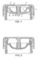
- Figure 1 shows the lid sealed to the neck 2 of a carbonated beverage bottle.
- the lid comprises a cap member 4, a diaphragm member 6 and a piston member 8.
- These three members are injection moulded plastic components of e.g. polyethylene or polypropylene.
- the cap member comprises a circular generally planar lid plate 10, which, in use, extends over the mouth of the bottle or other container. Integrally connected to its outer edge is a depending skirt 12. In this case, the inner surface of the skirt 12 carries short start screw threads 14, though the cap may be connected to the bottle in any conventional manner. Integral with the underside of the lid plate 10 is an annular sealing bead or ridge 16 and situated inwardly from it is an integral depending lug 18. Also extending integrally from the centre of the underside of the lid plate is a spigot 20. The function of these elements will be described below.
- the diaphragm member 6 which comprises a stationary portion and a movable portion.
- the stationary portion comprises an annular depending wall 22, integral with whose upper end is a radially outwardly extending, annular sealing flange 24 and integral with whose lower end is a radially inwardly extending annular support flange 26.
- Connected to the inner edge of the support flange 26 is the movable portion comprising a generally circular plate 28.
- the movability of the portion 28 is created by the provision of a number, in this case two, of annular fold lines 30 of opposite sense.
- a discharge aperture 32 is formed in the centre of the movable portion 28.
- Formed at the top of the wall 22 is a gas supply aperture 34 of small diameter, e.g. 1 mm or less, in this case 0.2 mm.
- the piston member 8 comprises a substantially rigid, circular dished plate 36, formed at whose outer edge is a relatively massive sealing flange 38.
- a cut-out 40 is formed in the upper surface of the flange 38 at one circumferential position.
- Formed in the centre of the plate 36 is a hole, extending around which is an open-ended tube 42, which is integral with and upstanding from the margin of the hole.
- the upper surface of the flange 24 is sealed to the underside of the lid plate 10, and the integrity of this seal is enhanced by the sealing bead 16.
- the seal may be created by welding or adhesive or may just rely on the pressure exerted on the flange 24 by the cap member, when it is fastened to the bottle and sandwiches the flange 24 between the cap member and the rim of the bottle.
- the diaphragm member and cap member are angularly orientated with respect to one another such that the sealing lug 18, which is deformed inwardly somewhat against its own resilience, engages the inner surface of the wall 22 over the aperture 34.
- the lug 18 and aperture 34 thus constitute a one-way valve which will permit gas to flow into but not out of the interior of the diaphragm member.
- the tube 42 of the piston member is slid over the spigot 20 on the cap member and forms a sliding seal with it.
- the spigot 20 is also pushed through the discharge aperture 32 in the diaphragm member, with which it also forms a sliding seal.
- the piston member and the diaphragm member are angularly orientated with respect to one another such that the gas aperture 34 is aligned with the cut-out 40 in the flange 38 of the piston member.
- the diaphragm member and cap member thus define a space, which is divided into two spaces by the piston member 8.
- the lower space 44 is referred to as an ingredient space and the upper space 46 is referred to as a gas space.
- the gas space 46 communicates with the gas aperture 34 via the cut-out 40.
- the spigot 20 carries an abutment which prevents movements of the piston member beyond a predetermined position.
- the abutment comprises a downwardly directed annular shoulder 21 formed on the spigot, which is engaged by the hollow tube 42.
- the ingredient space 44 is filled during assembly with a preselected ingredient, for instance lime syrup if the bottle is intended to contain lager and lime.
- a preselected ingredient for instance lime syrup if the bottle is intended to contain lager and lime.
- the cap member 4 is initially inverted and the piston member is then positioned within it and the tube 42 is slid down the spigot 20 until its free end engages the shoulder 21.
- the diaphragm member 6 is then inserted into the cap member with its internal surface in sealing contact with the peripheral edge of the piston member.
- the piston member may be placed within the diaphragm member and the two members are then inserted into the cap member together.
- the diaphragm member is then optionally sealed to the cap member.
- the movable wall portion When the diaphragm member is inserted, the movable wall portion is not initially slid over the spigot and it is then bent away, as shown in Figure 6 , to provide access to the ingredient space 44 for an ingredient injection nozzle 45.
- the ingredient in this case lime syrup, is then injected into the ingredient space.
- the movable wall portion of the diaphragm member is then slid over the spigot, which forms a sliding seal with the surface of the discharge aperture in the movable wall portion.
- the configuration is then as shown in Figure 7 , which is essentially the same as Figure 1 .
- the bottle is now filled, in this case with lager, and as soon as the lid is sealed to the bottle, carbon dioxide liberated from the lager will progressively increase the pressure in the head space of the bottle to a substantial superatmospheric value.
- This pressure acts on the gas aperture 34 and displaces the lug 18 somewhat inwardly and the gas space 46 is thus progressively pressurised also until the pressure in the gas space is substantially equal to the pressure in the head space of the bottle.
- the lid is removed. As the removal process starts, the seal between the lid and the neck of the bottle is broken and the pressure in the head space of the bottle drops virtually instantaneously to atmospheric pressure.
- the sealing lug 18 is biased by its resilience against the inner surface of the wall 2 and the gas supply aperture is therefore sealed.
- the pressure in the gas space is thus maintained and there is thus a substantial pressure differential across both the piston member 8 and the movable portion 28 of the diaphragm member.
- the movable member 28 thus moves downwardly under the influence of this pressure differential and such movement is permitted by the fold lines 30.
- the annular portions of the diaphragm member on each side of each fold line thus rotate in opposite senses relative to one another. After moving a short distance, the discharge aperture 32 in the diaphragm member moves out of engagement with the spigot 20 and the ingredient space is no longer sealed but communicates with the head space of the bottle through the aperture 32.
- Figure 8 shows a modified embodiment in which the seal member comprises a separate plate.
- This plate is in this case integral with the diaphragm member and connected to the upper outer edge of the diaphragm member at one circumferential position by an integral hinge 52.
- the seal member 50 comprises a circular plate, integral with which is the spigot 20.
- the insert shown in Figure 8 comprises the diaphragm member 6, the seal plate 50 and the piston member 8. This insert may then be placed within a cap member 4 and secured to it, e.g. by heat sealing or adhesive or it may simply be a push fit.
- the shoulder 21 has been omitted and the abutment is constituted by the free end of the tube 42, which is pushed into contact with the underside of the sealing plate 50.
- the insert is as described in relation to Figures 1 to 5 .
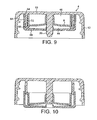
- FIG. 9 A modified container lid is shown in Figures 9 and 10 which differs from the embodiment of Figures 1 to 7 in several important respects.
- the depending annular wall 22 is integral with the lid plate 10, whereby the lid plate 10, the depending skirt 12, the spigot 20 and the depending wall 22 all constitute part of a one-piece injection moulding.
- the movable wall has no annular fold lines formed in it but is instead of generally cup shape and comprises a circular base 60, integral with whose outer edge is an upstanding annular wall 62.
- the internal surface of the wall 62 is in sliding engagement with the external surface of the depending wall 22 and the movable wall therefore cooperates with the depending wall 22 of the cap member in the manner of a piston and cylinder.
- peripheral bead or projection 64 Formed at the top of the internal surface of the wall 62 is a peripheral bead or projection 64 and formed at the bottom of the external surface of the depending wall 22 is a similar peripheral bead or projection 66.
- the presence of these two projections 64, 66 means that only limited sliding movement of the movable portions 60, 62 away from the cap member is possible and once the two projections 64, 66 come into engagement, further movement is prevented, whereby the cap member and the movable portions 60, 62 may be moved together as a unit.
- the pressure in the gas space 46 rises progressively to equal that in the head space of the bottle as a result of leakage through the gas leakage pathway described above.
- the pressure in the head space of the bottle drops instantaneously to atmospheric whilst the pressure in the gas space 46 remains at a high level because the rate of gas flow through the gas leakage path is very small.
- the pressure differential acting on the base 60 results in the movable portions 60, 62 rapidly moving downwards until the projections 64, 66 are in contact with one another. In the course of this movement, the spigot 42 moves out of the discharge aperture in the base 60.
- the pressure differential acting on the movable piston member 8 causes it to move downwards also, thereby expelling whatever liquid is within the ingredient space 44 through the discharge aperture 32 into the body of the bottle. This occurs before unscrewing of the lid from the bottle has been completed and when the cap member is removed from the bottle, the movable portions 60, 62 and the piston member 8 are removed with it.
Landscapes
- Engineering & Computer Science (AREA)
- Mechanical Engineering (AREA)
- Closures For Containers (AREA)
- Cartons (AREA)
Claims (13)
- Einsatz für einen Mehrkomponentenbehälter mit einem oberen Dichtelement (10), einer zur Unterseite des Dichtelements (10) abgedichteten herabhängenden Ringwand (22), einem mit der Unterseite des Dichtelements (10) verbundenen herabhängenden Zapfen (20) und einer von der herabhängenden Wand (22) getragenen beweglichen Wand (28;60), wobei das Dichtelement (10), die herabhängende Wand (22) und die bewegliche Wand (28;60) einen Innenraum begrenzen, die bewegliche Wand (28;60) unter der Wirkung eines Drucks im Innenraum relativ zur herabhängende Wand (22) beweglich ist und eine Abgabeöffnung (32) bildet, in welcher der Zapfen (20) gleitend und dichtend aufgenommen ist, dadurch gekennzeichnet, dass der Innenraum ein bewegliches Kolbenelement (8) aufnimmt, welches den Innenraum in zwei Räume, nämlich einen Gasraum (46) und einen darunter befindlichen Ingrediensraum (44), teilt, wobei der Außenrand des Kolbenelements (8) mit der Innenwand der herabhängenden Wand (22) eine Gleitdichtung bildet und ein Loch im Kolbenelement ausgebildet ist, in welchem der Zapfen (20) gleitend und dichtend aufgenommen ist, wobei eine Gaszuleitung (34) mit dem Gasraum (46) in Verbindung steht, welche Gaszuleitung (34) so konstruiert ist, dass sie Gas von außerhalb der herabhängenden Wand (22) in den Gasraum (46) strömen lässt, aber ein Strömen in der entgegengesetzten Richtung im Wesentlichen verhindert.
- Einsatz nach Anspruch 1, bei welchem die bewegliche Wand mit der herabhängenden Wand integral ausgebildet und durch mindestens zwei ringförmige Falzlinien entgegengesetzter Richtung, innerhalb derer die Abgabeöffnung gebildet ist, mit dieser verbunden ist.
- Einsatz nach Anspruch 1, wobei die bewegliche Wand eine Basis aufweist, die mit einer aufragenden Ringwand verbunden ist, welche in gleitendem Eingriff mit der herabhängenden Wand steht, wobei die bewegliche Wand mit der herabhängenden Wand nach Art eines Kolbens und Zylinders zusammenwirkt.
- Einsatz nach Anspruch 3, wobei die herabhängende Wand und die aufragende Wand entsprechende Vorsprünge aufweisen, die zusammenwirken, um eine nur begrenzte relative Gleitbewegung zuzulassen, wobei die herabhängende Wand und die bewegliche Wand miteinander verbunden sind und miteinander als Einheit bewegt werden können.
- Einsatz nach einem der vorhergehenden Ansprüche, wobei die Gaszuleitung einen Gasleckleitungsweg bildet, der sich durch die herabhängende Wand erstreckt und so dimensioniert ist, dass Gas nur relativ langsam durchströmen kann.
- Einsatz nach Anspruch 5 mit einer nachgiebigen Lasche, die von der Unterseite des Dichtelements herabhängt und an der Innenfläche der herabhängenden Wand über der Gaszufuhröffnung angreift und mit letzterer ein Rückschlagventil bildet.
- Einsatz nach Anspruch 5 oder 6, wobei der Außenrand des Kolbenelements einen relativ massiven Flansch bildet, in dessen Oberseite an einer vorherbestimmten Umfangsstelle ein Ausschnitt vorgesehen ist, wobei die Gaszufuhröffnung über den Ausschnitt mit dem Gasraum in Verbindung steht.
- Einsatz nach einem der Ansprüche 1 bis 4, wobei die Gaszuleitung einen Gasleckleitungsweg bildet, der zwischen dem Zapfen und den Rändern der Abgabeöffnung und dem Loch im Kolbenelement festgelegt ist.
- Einsatz nach einem der vorhergehenden Ansprüche, wobei das Dichtelement eine Platte aufweist, die mit der herabhängenden Wand integral verbunden ist.
- Einsatz nach einem der vorhergehenden Ansprüche, wobei der Zapfen und/oder das Kolbenelement ein Widerlager aufweist, an welchem das Kolbenelement bzw. das Dichtelement angreift und welches einen vorherbestimmten Mindestabstand zwischen dem Dichtelement und dem Kolbenelement aufrechterhält.
- Deckel für einen Mehrkomponentenbehälter mit einem Einsatz nach einem der vorhergehenden Ansprüche.
- Deckel nach Anspruch 11, wobei der Deckel eine Deckelplatte aufweist, gegenüber welcher das obere Ende der herabhängenden Wand abgedichtet ist, wobei die Deckelplatte das Dichtelement bildet.
- Mehrkomponentenbehälter mit einem Hals, der eine Öffnung definiert, welche durch einen Deckel nach Anspruch 11 abgedichtet ist, wobei die herabhängende Wand an ihrem oberen Ende mit einem sich radial nach außen erstreckenden Flansch integral ausgebildet ist, welcher Flansch sandwichartig zwischen der Unterseite der Deckelplatte und der Oberseite des Behälterhalses angeordnet ist.
Applications Claiming Priority (3)
| Application Number | Priority Date | Filing Date | Title |
|---|---|---|---|
| GB0614873A GB0614873D0 (en) | 2006-07-26 | 2006-07-26 | Inserts for multiple component containers |
| GB0622698A GB0622698D0 (en) | 2006-11-14 | 2006-11-14 | Inserts for multiple component containers |
| PCT/GB2007/002608 WO2008012499A1 (en) | 2006-07-26 | 2007-07-12 | Inserts for multiple component containers |
Publications (2)
| Publication Number | Publication Date |
|---|---|
| EP2043924A1 EP2043924A1 (de) | 2009-04-08 |
| EP2043924B1 true EP2043924B1 (de) | 2011-12-28 |
Family
ID=38564527
Family Applications (1)
| Application Number | Title | Priority Date | Filing Date |
|---|---|---|---|
| EP07766195A Not-in-force EP2043924B1 (de) | 2006-07-26 | 2007-07-12 | Einsätze für mehrfachkomponentenbehälter |
Country Status (6)
| Country | Link |
|---|---|
| US (1) | US7806258B2 (de) |
| EP (1) | EP2043924B1 (de) |
| JP (1) | JP5009988B2 (de) |
| AT (1) | ATE539009T1 (de) |
| AU (1) | AU2007279067B2 (de) |
| WO (1) | WO2008012499A1 (de) |
Families Citing this family (7)
| Publication number | Priority date | Publication date | Assignee | Title |
|---|---|---|---|---|
| JP5351051B2 (ja) * | 2007-02-20 | 2013-11-27 | リー、ジュンミン | 異種物質受容装置 |
| US20110247217A1 (en) * | 2010-04-12 | 2011-10-13 | Robert Harold Johnson | Shaving cartridge having a front pivoting hood with a biasing member |
| CH703940A2 (de) * | 2010-10-13 | 2012-04-13 | Rm Beteiligungs Ag | Kunststoffverschluss mit Kapsel zur Abgabe von Wirkstoffen. |
| US8403166B2 (en) | 2011-05-31 | 2013-03-26 | Zak Designs, Inc. | Sealable storage container |
| JP7250492B2 (ja) * | 2018-11-30 | 2023-04-03 | 株式会社吉野工業所 | 混合容器 |
| WO2020142698A1 (en) * | 2019-01-05 | 2020-07-09 | Foremost Technologies and Products, Inc. | High pressure processing of foods and supplements |
| EP4573023A1 (de) * | 2022-08-19 | 2025-06-25 | H.J. Heinz Company Brands LLC | Spenderkappe, einsetzbare kartusche, spenderbehälter, spendersystem und verfahren zur herstellung und verwendung |
Family Cites Families (14)
| Publication number | Priority date | Publication date | Assignee | Title |
|---|---|---|---|---|
| JPS5018847Y1 (de) * | 1969-03-24 | 1975-06-09 | ||
| NL7413077A (nl) * | 1974-10-03 | 1976-04-06 | Leer Koninklijke Emballage | Houder met schroefdop. |
| US4197943A (en) * | 1978-08-14 | 1980-04-15 | Weikel Maurice M | Dental alloy container |
| WO1993024384A1 (en) * | 1992-06-04 | 1993-12-09 | Edward Roger Costello | Inserts for drinks containers |
| US5335773A (en) * | 1993-07-02 | 1994-08-09 | Habley Medical Technology Corporation | Multi-pharmaceutical storage, mixing and dispensing vial |
| US5330048A (en) * | 1993-07-09 | 1994-07-19 | Habley Medical Technology Corporation | Controlled access mixing vial |
| JPH07223681A (ja) * | 1994-02-09 | 1995-08-22 | Kamaya Kagaku Kogyo Co Ltd | 二剤混合容器 |
| DE69602949T2 (de) * | 1995-07-29 | 2000-02-17 | Rocep-Lusol Holdings Ltd., Renfrew | Verfahren zum mischen eines fluids mit einer flüssigkeit |
| JPH11208735A (ja) * | 1998-01-22 | 1999-08-03 | Maeda Sangyo Kk | 2成分混合容器ユニットおよび2成分混合容器ユニット用第2成分容器 |
| JP2000072185A (ja) * | 1998-08-28 | 2000-03-07 | Toto Ltd | 二液混合容器 |
| US7735641B2 (en) * | 2003-10-28 | 2010-06-15 | Andrey Vyacheslavovich Agarkov | Vessels for multicomponent products |
| WO2005097615A1 (en) | 2004-04-08 | 2005-10-20 | Jeong-Min Lee | Structure of cap having inner cap |
| US7588142B1 (en) * | 2005-11-18 | 2009-09-15 | Rexam Closures And Containers Inc. | Additive delivery system closure |
| GB0601018D0 (en) * | 2006-01-18 | 2006-03-01 | Carbonite Corp | Inserts for multiple component containers |
-
2007
- 2007-07-12 JP JP2009521327A patent/JP5009988B2/ja not_active Expired - Fee Related
- 2007-07-12 AT AT07766195T patent/ATE539009T1/de active
- 2007-07-12 EP EP07766195A patent/EP2043924B1/de not_active Not-in-force
- 2007-07-12 US US12/374,042 patent/US7806258B2/en not_active Expired - Fee Related
- 2007-07-12 AU AU2007279067A patent/AU2007279067B2/en not_active Ceased
- 2007-07-12 WO PCT/GB2007/002608 patent/WO2008012499A1/en not_active Ceased
Also Published As
| Publication number | Publication date |
|---|---|
| EP2043924A1 (de) | 2009-04-08 |
| AU2007279067A1 (en) | 2008-01-31 |
| AU2007279067B2 (en) | 2012-07-26 |
| US20090308765A1 (en) | 2009-12-17 |
| US7806258B2 (en) | 2010-10-05 |
| JP2009544542A (ja) | 2009-12-17 |
| ATE539009T1 (de) | 2012-01-15 |
| WO2008012499A1 (en) | 2008-01-31 |
| JP5009988B2 (ja) | 2012-08-29 |
Similar Documents
| Publication | Publication Date | Title |
|---|---|---|
| US7886899B2 (en) | Container closure having means for introducing an additive into the contents of the container | |
| CA2838459C (en) | Container closure having means for introducing an additive into the contents of the container | |
| US20090321286A1 (en) | Container closure having a lifting cap for introducing an additive into the contents of the container | |
| EP2043924B1 (de) | Einsätze für mehrfachkomponentenbehälter | |
| CA2297521A1 (en) | Beverage container with cap and spout | |
| MX2013004042A (es) | Cierre de plástico que tiene una cápsula para surtir ingredientes activos. | |
| WO2008002160A2 (en) | Cap with a capsule rupturable by a cutter | |
| EP3947179B1 (de) | Verschlusskappe für einen behälter | |
| US7832590B2 (en) | Inserts for multiple component containers | |
| CN101495382B (zh) | 用于多成分容器的盖子、插入件和容器 | |
| EP1973799B1 (de) | Einsätze für mehrfachkomponentenbehälter | |
| HK1122254B (en) | Inserts for multiple component containers | |
| HK1190686B (en) | Dispensing cap for a container |
Legal Events
| Date | Code | Title | Description |
|---|---|---|---|
| PUAI | Public reference made under article 153(3) epc to a published international application that has entered the european phase |
Free format text: ORIGINAL CODE: 0009012 |
|
| 17P | Request for examination filed |
Effective date: 20090130 |
|
| AK | Designated contracting states |
Kind code of ref document: A1 Designated state(s): AT BE BG CH CY CZ DE DK EE ES FI FR GB GR HU IE IS IT LI LT LU LV MC MT NL PL PT RO SE SI SK TR |
|
| AX | Request for extension of the european patent |
Extension state: AL BA HR MK RS |
|
| GRAP | Despatch of communication of intention to grant a patent |
Free format text: ORIGINAL CODE: EPIDOSNIGR1 |
|
| DAX | Request for extension of the european patent (deleted) | ||
| GRAS | Grant fee paid |
Free format text: ORIGINAL CODE: EPIDOSNIGR3 |
|
| GRAA | (expected) grant |
Free format text: ORIGINAL CODE: 0009210 |
|
| AK | Designated contracting states |
Kind code of ref document: B1 Designated state(s): AT BE BG CH CY CZ DE DK EE ES FI FR GB GR HU IE IS IT LI LT LU LV MC MT NL PL PT RO SE SI SK TR |
|
| REG | Reference to a national code |
Ref country code: GB Ref legal event code: FG4D |
|
| REG | Reference to a national code |
Ref country code: CH Ref legal event code: EP |
|
| REG | Reference to a national code |
Ref country code: AT Ref legal event code: REF Ref document number: 539009 Country of ref document: AT Kind code of ref document: T Effective date: 20120115 |
|
| REG | Reference to a national code |
Ref country code: IE Ref legal event code: FG4D |
|
| REG | Reference to a national code |
Ref country code: DE Ref legal event code: R096 Ref document number: 602007019696 Country of ref document: DE Effective date: 20120308 |
|
| REG | Reference to a national code |
Ref country code: NL Ref legal event code: VDEP Effective date: 20111228 |
|
| PG25 | Lapsed in a contracting state [announced via postgrant information from national office to epo] |
Ref country code: LT Free format text: LAPSE BECAUSE OF FAILURE TO SUBMIT A TRANSLATION OF THE DESCRIPTION OR TO PAY THE FEE WITHIN THE PRESCRIBED TIME-LIMIT Effective date: 20111228 |
|
| LTIE | Lt: invalidation of european patent or patent extension |
Effective date: 20111228 |
|
| PG25 | Lapsed in a contracting state [announced via postgrant information from national office to epo] |
Ref country code: SE Free format text: LAPSE BECAUSE OF FAILURE TO SUBMIT A TRANSLATION OF THE DESCRIPTION OR TO PAY THE FEE WITHIN THE PRESCRIBED TIME-LIMIT Effective date: 20111228 Ref country code: GR Free format text: LAPSE BECAUSE OF FAILURE TO SUBMIT A TRANSLATION OF THE DESCRIPTION OR TO PAY THE FEE WITHIN THE PRESCRIBED TIME-LIMIT Effective date: 20120329 Ref country code: LV Free format text: LAPSE BECAUSE OF FAILURE TO SUBMIT A TRANSLATION OF THE DESCRIPTION OR TO PAY THE FEE WITHIN THE PRESCRIBED TIME-LIMIT Effective date: 20111228 Ref country code: SI Free format text: LAPSE BECAUSE OF FAILURE TO SUBMIT A TRANSLATION OF THE DESCRIPTION OR TO PAY THE FEE WITHIN THE PRESCRIBED TIME-LIMIT Effective date: 20111228 |
|
| PG25 | Lapsed in a contracting state [announced via postgrant information from national office to epo] |
Ref country code: CY Free format text: LAPSE BECAUSE OF FAILURE TO SUBMIT A TRANSLATION OF THE DESCRIPTION OR TO PAY THE FEE WITHIN THE PRESCRIBED TIME-LIMIT Effective date: 20111228 Ref country code: BE Free format text: LAPSE BECAUSE OF FAILURE TO SUBMIT A TRANSLATION OF THE DESCRIPTION OR TO PAY THE FEE WITHIN THE PRESCRIBED TIME-LIMIT Effective date: 20111228 |
|
| PG25 | Lapsed in a contracting state [announced via postgrant information from national office to epo] |
Ref country code: CZ Free format text: LAPSE BECAUSE OF FAILURE TO SUBMIT A TRANSLATION OF THE DESCRIPTION OR TO PAY THE FEE WITHIN THE PRESCRIBED TIME-LIMIT Effective date: 20111228 Ref country code: NL Free format text: LAPSE BECAUSE OF FAILURE TO SUBMIT A TRANSLATION OF THE DESCRIPTION OR TO PAY THE FEE WITHIN THE PRESCRIBED TIME-LIMIT Effective date: 20111228 Ref country code: BG Free format text: LAPSE BECAUSE OF FAILURE TO SUBMIT A TRANSLATION OF THE DESCRIPTION OR TO PAY THE FEE WITHIN THE PRESCRIBED TIME-LIMIT Effective date: 20120328 Ref country code: SK Free format text: LAPSE BECAUSE OF FAILURE TO SUBMIT A TRANSLATION OF THE DESCRIPTION OR TO PAY THE FEE WITHIN THE PRESCRIBED TIME-LIMIT Effective date: 20111228 Ref country code: EE Free format text: LAPSE BECAUSE OF FAILURE TO SUBMIT A TRANSLATION OF THE DESCRIPTION OR TO PAY THE FEE WITHIN THE PRESCRIBED TIME-LIMIT Effective date: 20111228 Ref country code: IS Free format text: LAPSE BECAUSE OF FAILURE TO SUBMIT A TRANSLATION OF THE DESCRIPTION OR TO PAY THE FEE WITHIN THE PRESCRIBED TIME-LIMIT Effective date: 20120428 |
|
| PG25 | Lapsed in a contracting state [announced via postgrant information from national office to epo] |
Ref country code: PT Free format text: LAPSE BECAUSE OF FAILURE TO SUBMIT A TRANSLATION OF THE DESCRIPTION OR TO PAY THE FEE WITHIN THE PRESCRIBED TIME-LIMIT Effective date: 20120430 Ref country code: RO Free format text: LAPSE BECAUSE OF FAILURE TO SUBMIT A TRANSLATION OF THE DESCRIPTION OR TO PAY THE FEE WITHIN THE PRESCRIBED TIME-LIMIT Effective date: 20111228 Ref country code: PL Free format text: LAPSE BECAUSE OF FAILURE TO SUBMIT A TRANSLATION OF THE DESCRIPTION OR TO PAY THE FEE WITHIN THE PRESCRIBED TIME-LIMIT Effective date: 20111228 |
|
| REG | Reference to a national code |
Ref country code: AT Ref legal event code: MK05 Ref document number: 539009 Country of ref document: AT Kind code of ref document: T Effective date: 20111228 |
|
| PG25 | Lapsed in a contracting state [announced via postgrant information from national office to epo] |
Ref country code: DK Free format text: LAPSE BECAUSE OF FAILURE TO SUBMIT A TRANSLATION OF THE DESCRIPTION OR TO PAY THE FEE WITHIN THE PRESCRIBED TIME-LIMIT Effective date: 20111228 |
|
| PLBE | No opposition filed within time limit |
Free format text: ORIGINAL CODE: 0009261 |
|
| STAA | Information on the status of an ep patent application or granted ep patent |
Free format text: STATUS: NO OPPOSITION FILED WITHIN TIME LIMIT |
|
| PG25 | Lapsed in a contracting state [announced via postgrant information from national office to epo] |
Ref country code: IT Free format text: LAPSE BECAUSE OF FAILURE TO SUBMIT A TRANSLATION OF THE DESCRIPTION OR TO PAY THE FEE WITHIN THE PRESCRIBED TIME-LIMIT Effective date: 20111228 |
|
| 26N | No opposition filed |
Effective date: 20121001 |
|
| REG | Reference to a national code |
Ref country code: DE Ref legal event code: R097 Ref document number: 602007019696 Country of ref document: DE Effective date: 20121001 |
|
| PG25 | Lapsed in a contracting state [announced via postgrant information from national office to epo] |
Ref country code: AT Free format text: LAPSE BECAUSE OF FAILURE TO SUBMIT A TRANSLATION OF THE DESCRIPTION OR TO PAY THE FEE WITHIN THE PRESCRIBED TIME-LIMIT Effective date: 20111228 |
|
| PG25 | Lapsed in a contracting state [announced via postgrant information from national office to epo] |
Ref country code: MC Free format text: LAPSE BECAUSE OF NON-PAYMENT OF DUE FEES Effective date: 20120731 |
|
| REG | Reference to a national code |
Ref country code: CH Ref legal event code: PL |
|
| PG25 | Lapsed in a contracting state [announced via postgrant information from national office to epo] |
Ref country code: CH Free format text: LAPSE BECAUSE OF NON-PAYMENT OF DUE FEES Effective date: 20120731 Ref country code: ES Free format text: LAPSE BECAUSE OF FAILURE TO SUBMIT A TRANSLATION OF THE DESCRIPTION OR TO PAY THE FEE WITHIN THE PRESCRIBED TIME-LIMIT Effective date: 20120408 Ref country code: LI Free format text: LAPSE BECAUSE OF NON-PAYMENT OF DUE FEES Effective date: 20120731 |
|
| REG | Reference to a national code |
Ref country code: IE Ref legal event code: MM4A |
|
| PG25 | Lapsed in a contracting state [announced via postgrant information from national office to epo] |
Ref country code: FI Free format text: LAPSE BECAUSE OF FAILURE TO SUBMIT A TRANSLATION OF THE DESCRIPTION OR TO PAY THE FEE WITHIN THE PRESCRIBED TIME-LIMIT Effective date: 20111228 |
|
| PG25 | Lapsed in a contracting state [announced via postgrant information from national office to epo] |
Ref country code: MT Free format text: LAPSE BECAUSE OF FAILURE TO SUBMIT A TRANSLATION OF THE DESCRIPTION OR TO PAY THE FEE WITHIN THE PRESCRIBED TIME-LIMIT Effective date: 20111228 Ref country code: IE Free format text: LAPSE BECAUSE OF NON-PAYMENT OF DUE FEES Effective date: 20120712 |
|
| PGFP | Annual fee paid to national office [announced via postgrant information from national office to epo] |
Ref country code: DE Payment date: 20130729 Year of fee payment: 7 |
|
| PGFP | Annual fee paid to national office [announced via postgrant information from national office to epo] |
Ref country code: FR Payment date: 20130731 Year of fee payment: 7 |
|
| PG25 | Lapsed in a contracting state [announced via postgrant information from national office to epo] |
Ref country code: TR Free format text: LAPSE BECAUSE OF FAILURE TO SUBMIT A TRANSLATION OF THE DESCRIPTION OR TO PAY THE FEE WITHIN THE PRESCRIBED TIME-LIMIT Effective date: 20111228 |
|
| PG25 | Lapsed in a contracting state [announced via postgrant information from national office to epo] |
Ref country code: LU Free format text: LAPSE BECAUSE OF NON-PAYMENT OF DUE FEES Effective date: 20120712 |
|
| PG25 | Lapsed in a contracting state [announced via postgrant information from national office to epo] |
Ref country code: HU Free format text: LAPSE BECAUSE OF FAILURE TO SUBMIT A TRANSLATION OF THE DESCRIPTION OR TO PAY THE FEE WITHIN THE PRESCRIBED TIME-LIMIT Effective date: 20070712 |
|
| PGFP | Annual fee paid to national office [announced via postgrant information from national office to epo] |
Ref country code: GB Payment date: 20140731 Year of fee payment: 8 |
|
| REG | Reference to a national code |
Ref country code: DE Ref legal event code: R119 Ref document number: 602007019696 Country of ref document: DE |
|
| REG | Reference to a national code |
Ref country code: FR Ref legal event code: ST Effective date: 20150331 |
|
| PG25 | Lapsed in a contracting state [announced via postgrant information from national office to epo] |
Ref country code: DE Free format text: LAPSE BECAUSE OF NON-PAYMENT OF DUE FEES Effective date: 20150203 |
|
| REG | Reference to a national code |
Ref country code: DE Ref legal event code: R119 Ref document number: 602007019696 Country of ref document: DE Effective date: 20150203 |
|
| PG25 | Lapsed in a contracting state [announced via postgrant information from national office to epo] |
Ref country code: FR Free format text: LAPSE BECAUSE OF NON-PAYMENT OF DUE FEES Effective date: 20140731 |
|
| GBPC | Gb: european patent ceased through non-payment of renewal fee |
Effective date: 20150712 |
|
| PG25 | Lapsed in a contracting state [announced via postgrant information from national office to epo] |
Ref country code: GB Free format text: LAPSE BECAUSE OF NON-PAYMENT OF DUE FEES Effective date: 20150712 |