EP2043927B1 - Flüssigproduktspender - Google Patents
Flüssigproduktspender Download PDFInfo
- Publication number
- EP2043927B1 EP2043927B1 EP07823528A EP07823528A EP2043927B1 EP 2043927 B1 EP2043927 B1 EP 2043927B1 EP 07823528 A EP07823528 A EP 07823528A EP 07823528 A EP07823528 A EP 07823528A EP 2043927 B1 EP2043927 B1 EP 2043927B1
- Authority
- EP
- European Patent Office
- Prior art keywords
- dispenser
- wall
- fluid
- reservoir
- orifice
- Prior art date
- Legal status (The legal status is an assumption and is not a legal conclusion. Google has not performed a legal analysis and makes no representation as to the accuracy of the status listed.)
- Active
Links
Images
Classifications
-
- B—PERFORMING OPERATIONS; TRANSPORTING
- B65—CONVEYING; PACKING; STORING; HANDLING THIN OR FILAMENTARY MATERIAL
- B65D—CONTAINERS FOR STORAGE OR TRANSPORT OF ARTICLES OR MATERIALS, e.g. BAGS, BARRELS, BOTTLES, BOXES, CANS, CARTONS, CRATES, DRUMS, JARS, TANKS, HOPPERS, FORWARDING CONTAINERS; ACCESSORIES, CLOSURES, OR FITTINGS THEREFOR; PACKAGING ELEMENTS; PACKAGES
- B65D83/00—Containers or packages with special means for dispensing contents
- B65D83/0094—Containers having an external wall formed as, or with, a diaphragm or the like which is deformed to expel the contents
-
- A—HUMAN NECESSITIES
- A45—HAND OR TRAVELLING ARTICLES
- A45D—HAIRDRESSING OR SHAVING EQUIPMENT; EQUIPMENT FOR COSMETICS OR COSMETIC TREATMENTS, e.g. FOR MANICURING OR PEDICURING
- A45D40/00—Casings or accessories specially adapted for storing or handling solid or pasty toiletry or cosmetic substances, e.g. shaving soaps or lipsticks
- A45D40/0068—Jars
- A45D40/0075—Jars with dispensing means
-
- B—PERFORMING OPERATIONS; TRANSPORTING
- B65—CONVEYING; PACKING; STORING; HANDLING THIN OR FILAMENTARY MATERIAL
- B65D—CONTAINERS FOR STORAGE OR TRANSPORT OF ARTICLES OR MATERIALS, e.g. BAGS, BARRELS, BOTTLES, BOXES, CANS, CARTONS, CRATES, DRUMS, JARS, TANKS, HOPPERS, FORWARDING CONTAINERS; ACCESSORIES, CLOSURES, OR FITTINGS THEREFOR; PACKAGING ELEMENTS; PACKAGES
- B65D83/00—Containers or packages with special means for dispensing contents
- B65D83/76—Containers or packages with special means for dispensing contents for dispensing fluent contents by means of a piston
- B65D83/765—Containers or packages with special means for dispensing contents for dispensing fluent contents by means of a piston the piston being a follower-piston and the dispensing means comprising a hand-operated pressure device at the opposite part of the container
-
- B—PERFORMING OPERATIONS; TRANSPORTING
- B65—CONVEYING; PACKING; STORING; HANDLING THIN OR FILAMENTARY MATERIAL
- B65D—CONTAINERS FOR STORAGE OR TRANSPORT OF ARTICLES OR MATERIALS, e.g. BAGS, BARRELS, BOTTLES, BOXES, CANS, CARTONS, CRATES, DRUMS, JARS, TANKS, HOPPERS, FORWARDING CONTAINERS; ACCESSORIES, CLOSURES, OR FITTINGS THEREFOR; PACKAGING ELEMENTS; PACKAGES
- B65D83/00—Containers or packages with special means for dispensing contents
- B65D83/76—Containers or packages with special means for dispensing contents for dispensing fluent contents by means of a piston
- B65D83/767—Containers or packages with special means for dispensing contents for dispensing fluent contents by means of a piston the piston having an integrated dispensing opening
-
- A—HUMAN NECESSITIES
- A45—HAND OR TRAVELLING ARTICLES
- A45D—HAIRDRESSING OR SHAVING EQUIPMENT; EQUIPMENT FOR COSMETICS OR COSMETIC TREATMENTS, e.g. FOR MANICURING OR PEDICURING
- A45D2200/00—Details not otherwise provided for in A45D
- A45D2200/05—Details of containers
- A45D2200/054—Means for supplying liquid to the outlet of the container
- A45D2200/055—Piston or plunger for supplying the liquid to the applicator
Definitions
- the present invention relates to a dispenser of more or less viscous fluid such as cream, gel, paw, lotion, perfume, etc.
- This dispenser comprises a fluid reservoir of variable volume in which the fluid product is stored out of contact with air.
- the reservoir is provided with an actuating wall axially displaceable back and forth between a rest position and a depressed position. The displacement of the wall varies the pressure inside the tank between vacuum phases and overpressure phases.
- the wall is located on one side of the dispenser.
- the dispenser comprises a dispensing orifice through which the fluid product is dispensed from the dispenser.
- the orifice is provided with a non-return check valve which prevents air from being drawn into the tank. This type of distributor is frequently found in the fields of perfumery, cosmetics, pharmacy and parapharmacy.
- the actuating wall is located near the dispensing orifice so that the depression of the actuating wall has the direct effect of putting the fluid product stored in the reservoir under pressure so that it is forced through the dispensing orifice.
- the outlet valve closes: the reservoir is then subjected to a depression, which has the effect of modifying its useful volume.
- This variation in useful volume can be effected for example because the reservoir is made from a deformable flexible bag.
- the reservoir forms a sliding shaft in which is engaged a follower piston.
- the depression has the effect of deforming the flexible pouch that will shrivel on itself.
- the object of the present invention is to provide a dispenser of this type having a configuration that avoids this design constraint.
- the present invention provides a dispenser having the features of the main claim.
- the actuating wall is located on another side than that of the dispensing orifice, the configuration is paradoxical, because it should be noted that the actuating wall does not act directly on the follower piston. but on the fluid product.
- the follower piston is at the bottom, and the orifice and the actuating wall at the top.
- a difficulty overcome by the present invention is to decouple the orifice and the actuating wall, while using a follower piston. And to do this, the follower piston can form a connecting conduit which communicates the reservoir with the dispensing orifice.
- this characteristic can be implemented independently of the fact that the actuating wall is opposite or uncoupled from the dispensing orifice.
- the combination of these two features is advantageous.
- the follower piston does not communicate directly with the dispensing orifice.
- the follower piston is generally located at the bottom of the tank and it moves by suction towards the dispensing orifice.
- the originality of this feature lies in the fact that the follower piston connects the reservoir to the dispensing orifice.
- the fluid dispenser comprises a bottom and a top, when positioned upright, the actuating wall being located at the bottom, the distributor resting, in the rest position and in the depressed position, on the actuating wall. .
- the actuation of the dispenser can thus be performed by pressing the dispenser, while its bottom rests on a bearing surface.
- the product is dispensed on the top or side of the dispenser.
- the wall and the follower piston move along a common axis X. They are separated by the fluid product stored in the reservoir. At each depression of the wall, fluid is dispensed and the follower piston remains static and at each release of the wall the follower piston moves.
- the conduit is in leaktight sliding engagement with a sleeve integral with the dispensing orifice, the conduit and the sleeve sliding relative to each other as the follower piston moves in the barrel.
- the barrel, the sleeve and the dispensing orifice are formed by a one-piece body.
- the body comprises an upper plate forming the top of the dispenser, the plate being formed with a hole which is advantageously provided with an outlet valve, so as to form together the dispensing orifice.
- the dispenser can be made from only three parts, namely the one-piece body, the follower piston and the actuating wall, if the outlet valve is omitted.
- the dispenser may comprise a one-piece body internally defining the fluid reservoir, the body being closed by a bottom forming the actuating wall.
- the reservoir is mainly formed by the bottom, the body and a follower piston, this follower piston being positioned between the bottom and the dispensing orifice.
- the body forms a sleeve integral with the dispensing orifice, the follower piston forming a duct engaged in leaktight sliding in the sleeve, the reservoir thus communicating with the dispensing orifice through the duct and the sleeve.
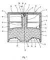
- the fluid dispenser according to the invention essentially comprises three component parts, namely a body 1, a bottom 2 and a follower piston 3.
- the distributor also comprises an outlet valve 4 or an attached nozzle.
- the dispenser may furthermore also be provided with a protective cover 5 which is removably mounted on the dispenser so as to mask the dispensing orifice.
- the body 1 is preferably made integrally of plastics material and comprises a barrel 11 of cylindrical shape, preferably circular, within which slides the follower piston 3, as will be seen below.
- the barrel 11 includes an open bottom end and an upper end which forms a shoulder 12 inwardly.
- the body 21 extends from this shoulder 12 upwards to form a ring 13 which can advantageously be used for fixing the protective cover 5.
- the body 1 forms a plate 14 which is here substantially circular.
- This plate 14 is substantially flat or concave and has a substantially central hole which will serve to define the dispensing orifice.
- a sleeve 16 extends from the hole towards the inside of the body so that the ring 13 extends concentrically with this sleeve 16.
- the plate 14 at the substantially central hole defines a hooking structure 144 which retains the valve 4.
- a hooking structure 144 which retains the valve 4.
- any outlet valve in the context of this invention for example can be used a valve in the form of a mushroom or umbrella comprising an anchor foot 41 engaged in the attachment structure 144 and a washer or corolla 42 whose edge comes into selective waterproof support on a valve seat 15 formed at the junction of the plate 14 with the sleeve 13 which defines the hole.
- the foot 41 can be fixed in place inside the attachment structure 144: in this case, the washer 42 is elastically deformable.
- the anchor foot 41 can move on a limited stroke inside the attachment structure 144: in this case, the washer 42 does not need to be elastically deformable.
- the washer 42 does not need to be elastically deformable.
- the protective cover 5 comprises a peripheral skirt 51 intended to come into frictional engagement, latching or screwing with the crown 13 and a cover wall 52 which covers the plate 14, with its central hole and its valve 4.
- the cover protection 5 can be entirely removed from the body 1, or alternatively, the cover can be hinged to the body.
- the cover 5 is made integrally with the body and connected thereto by a bridge of deformable material.
- the follower piston 3 conventionally comprises a sealing lip 31, which here is of the type with a double sealing contact.
- the sealing lip 31 is connected to a roof 32 which extends in its center by a axial conduit 33 which is open at both ends.
- the conduit 33 comprises a free end opposite the roof 32 and which forms a leaktight sliding lip 34.
- the conduit 33 is engaged inside the sleeve 16 so that the lip 34 can slide in a sealed manner inside the sleeve 16. It can also be envisaged that the conduit 33 is arranged around the sleeve 16: in this case, it is the free end of the sleeve 16 which is then provided with a sealing lip.
- the sealing lip 31 of the follower piston is engaged in leaktight sliding inside the barrel 11 of the body 1. In the initial starting position, the lip 31 is located in the upper part of the barrel 11. As and when of the use of the dispenser, this lip 31 will move towards the bottom of the barrel 11.
- the bottom 2 of the distributor is sealingly engaged in the open lower end of the barrel 11.
- the bottom 2 comprises a rigid annular cup 21 which is anchored on its outer periphery 22 in a sealed manner in the barrel 11.
- the inner periphery of the cup 21 is connected to a membrane 24 having a fixing heel connected to the cup.
- This elastically deformable membrane 24 is in the form of an annular dome which is closed at its center by an actuating wall 25.
- This wall 25 is situated substantially centrally with respect to the bottom 2 of the distributor.
- This actuating wall 25 is axially displaceable back and forth by deforming the flexible membrane 24. On the figure 1 the actuating wall 25 is in its rest position.
- the bottom 2 can be made integrally with a single plastic material.
- the bottom 2 can be made by bi-injection or co-molding from two different plastics.
- the bottom, and thus the actuating wall are in direct contact with the fluid, so that they form a tank wall element.
- the distributor On the figure 1 , the distributor is in its rest position with the tank 10 filled to the maximum, the lip 31 of the follower piston being in abutment against the shoulder 12.
- the valve 4 is closed so that there is no orifice of distribution.
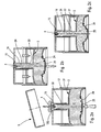
- the lip 34 is at its highest point in the sleeve 16. From this initial resting position, we will now describe, with reference to the Figures 2a, 2b and 2c a complete operating cycle of the dispenser according to the invention.
- the first step is to remove the cover 5, as shown in FIG. figure 2a . Then the user can exert pressure represented by the big arrow on the figure 2a at the level of the actuating wall 25. This has the effect of deforming the flexible membrane 24.
- the fluid product stored inside the tank 10 is put directly under pressure which has the effect of driving back part of the fluid product through the conduit 33 to the level of the valve 4 which is then forced in the open position to define an annular distribution port 150.
- This orifice is defined between the seat 15 and the washer 144.
- the follower piston remains static, with its sealing lip 31 in abutting contact with the shoulder 12.
- the distribution of the product continues until the actuating wall 25 reaches its maximum depressed position.
- the distribution of fluid product then stops at this moment and as soon as the pressure is released on the actuating wall 25, the valve 4 closes so that there is again no more orifice. 150.
- the wall 25 then returns to its initial rest position under the effect of the membrane 24 which tends to return to its original starting position because of its elastic shape memory.
- the membrane 24 therefore plays a role of return spring.
- the actuating wall 25 generates a depression inside the tank 10, which has the effect of sucking the follower piston 3 which then moves with a leaktight sliding inside. of the drum.
- the displacement of the follower piston is represented on the figure 2b by the two arrows on both sides of the conduit 33. Since this duct 33 is engaged in sealingly sliding inside the sleeve 16, the displacement of the follower piston in the barrel 11 also has the effect of moving the sealing lip 34 inside the sleeve 16.
- the follower piston makes a fluid connection between the reservoir 10 and the dispensing orifice.
- This fluidic connection makes it possible to produce a distributor without air intake whose reciprocating movable actuating wall is clearly separated from the dispensing orifice, and even situated on the opposite side.
- the actuating wall 25 is movable between two extreme positions, the fluid dispensing is perfectly metered. This produces a metering distributor without air intake whose actuating wall is located at the bottom and the dispensing orifice at the top. It is the follower piston itself which provides the connection between the reservoir and the dispensing orifice.
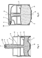
- the body 1 As for the body 1, it also comprises a shaft 11, a ring 13, a plate 14 and a sleeve 16, but it further comprises a dispensing nozzle 17 which terminates in a dispensing orifice 150.
- This dispenser also comprises a valve 4.
- the dispensing orifice 150 can also be made using a nozzle allowing a swirling of the fluid product.
- This nozzle can be integrated into the body 1 or made in the form of an insert.
- the distributor of the figure 3 comprises three component parts, namely the body 1, the bottom 2 and the follower piston 3.
- This dispenser can be used with one hand in the manner of a syringe, arranging the index and middle finger on the plate 14 from anterior part of the tip 17 and the thumb on the actuating wall 25. Unlike a conventional syringe, the fluid dispensing is perfectly dosed and the actuating wall returns to each actuation in its initial resting position.
- a dispenser may for example be used in pharmacies for the injection of various fluids into the natural orifices, such as nostrils or ears.
- the represented dispenser differs from that of the figure 3 essentially at the tip 17 and its bottom 2. Indeed, the tip is here more axial, but instead lateral.
- the dispensing orifice 150 is formed by a slotted shutter which opens under the pressure of the fluid product.
- the actuating wall 25 projects downwards and can thus constitute a bearing surface of the dispenser.
- the actuating wall is located at the bottom of the dispenser, but on the side or the top.
- the follower piston 3 can move horizontally.
Landscapes
- Engineering & Computer Science (AREA)
- Mechanical Engineering (AREA)
- Containers And Packaging Bodies Having A Special Means To Remove Contents (AREA)
Claims (11)
- Fluidproduktspender, aufweisend:- einen Behälter (10) für ein Fluid mit variablem Nutzvolumen, in dem das Fluid vor Luft geschützt gelagert ist, wobei der Behälter mit einer Betätigungswand (25) versehen ist, die zwischen einer Ruheposition und einer eingedrückten Position axial hin und her verstellbar ist, wobei durch die Verstellung der Wand der Druck in dem Behälter geändert wird, wobei sich die Wand auf einer Seite des Spenders befindet, und- eine Ausgabeöffnung (150), durch die das Fluid ausgegeben wird, wobei die Öffnung mit einer Auslassklappe (4) versehen ist, wobei sich die Öffnung (150) auf einer anderen Seite des Spenders befindet als die Seite, auf der sich die Betätigungswand (25) befindet,dadurch gekennzeichnet, dass der Behälter (10) einen Gleitzylinder (11) bildet, in den ein Nachlaufkolben (3) eingebunden ist, der dichtend in dem Kolben gleiten kann.
- Fluidproduktspender nach Anspruch 1, aufweisend einen Unterteil und einen Oberteil, wenn er aufrecht steht, wobei sich die Betätigungswand (25) unten befindet, wobei der Spender in der Ruheposition und in der eingedrückten Position auf der Betätigungswand ruht.
- Fluidproduktspender nach Anspruch 1, aufweisend einen Unterteil, einen Oberteil und Seitenwände, wobei sich die Betätigungswand auf einer Seitenwand befindet und sich die Ausgabeöffnung oben befindet.
- Spender für ein Fluid nach Anspruch 1, 2 oder 3, wobei sich die Wand (25) und der Nachlaufkolben (3) entlang einer gemeinsamen Achse X verschieben.
- Fluidproduktspender nach einem der vorhergehenden Ansprüche, wobei der Nachlaufkolben (3) eine Verbindungsleitung (33) bildet, die den Behälter mit der Ausgabeöffnung (150) verbindet.
- Fluidproduktspender nach Anspruch 5, wobei die Leitung (33) in dichtem, gleitendem Eingriff mit einer mit der Ausgabeöffnung (150) einstückig gebildeten Hülse (16) ist, wobei die Leitung und die Hülse so zueinander gleiten, dass sich der Nachlaufkolben (3) in dem Zylinder verschiebt.
- Fluidproduktspender nach Anspruch 6, wobei der Zylinder (11), die Hülse (16) und die Ausgabeöffnung (150) einstückig aus einem Körper (1) gebildet sind.
- Fluidproduktspender nach Anspruch 7, wobei der Körper (1) eine obere Platte (14) aufweist, die den Oberteil des Spenders bildet, wobei die Platte (14) mit einem Loch gebildet ist, das vorteilhafterweise mit einer Auslassklappe (4) versehen ist, so dass sie zusammen die Ausgabeöffnung (150) bilden.
- Fluidproduktspender nach einem der vorhergehenden Ansprüche, aufweisend einen einstückigen Körper (1), der innen den Fluidproduktbehälter (10) begrenzt, wobei der Körper durch einen Boden (2) verschlossen ist, der die Betätigungswand (25) bildet.
- Fluidproduktspender nach Anspruch 9, wobei der Behälter (10) in erster Linie durch den Boden (2), den Körper (1) und einen Nachlaufkolben (3) gebildet ist, wobei sich dieser Nachlaufkolben zwischen dem Boden und der Ausgabeöffnung befindet.
- Fluidproduktspender nach Anspruch 10, wobei der Körper (1) eine mit der Ausgabeöffnung (150) einstückige Hülse (16) bildet, wobei der Nachlaufkolben (3) eine Leitung (33) bildet, die dicht gleitend in die Hülse (16) eingebunden ist, wobei der Behälter (10) somit über die Leitung und die Hülse mit der Ausgabeöffnung (150) in Verbindung steht.
Applications Claiming Priority (2)
| Application Number | Priority Date | Filing Date | Title |
|---|---|---|---|
| FR0652780A FR2903092B1 (fr) | 2006-07-03 | 2006-07-03 | Distributeur de produit fluide |
| PCT/FR2007/051572 WO2008003894A2 (fr) | 2006-07-03 | 2007-07-02 | Distributeur de produit fluide |
Publications (2)
| Publication Number | Publication Date |
|---|---|
| EP2043927A2 EP2043927A2 (de) | 2009-04-08 |
| EP2043927B1 true EP2043927B1 (de) | 2010-09-15 |
Family
ID=37685845
Family Applications (1)
| Application Number | Title | Priority Date | Filing Date |
|---|---|---|---|
| EP07823528A Active EP2043927B1 (de) | 2006-07-03 | 2007-07-02 | Flüssigproduktspender |
Country Status (8)
| Country | Link |
|---|---|
| US (1) | US8556131B2 (de) |
| EP (1) | EP2043927B1 (de) |
| CN (1) | CN101500906B (de) |
| BR (1) | BRPI0713392A2 (de) |
| DE (1) | DE602007009252D1 (de) |
| ES (1) | ES2351889T3 (de) |
| FR (1) | FR2903092B1 (de) |
| WO (1) | WO2008003894A2 (de) |
Families Citing this family (14)
| Publication number | Priority date | Publication date | Assignee | Title |
|---|---|---|---|---|
| FR2957335B1 (fr) * | 2010-03-11 | 2012-09-14 | Cadorit Ag | Recipient |
| IT1399127B1 (it) * | 2010-04-01 | 2013-04-05 | Lameplast Spa | Dispositivo per la somministrazione di prodotti fluidi |
| CN101936969A (zh) * | 2010-08-11 | 2011-01-05 | 苏州大学 | 上样器 |
| KR101598120B1 (ko) * | 2013-06-25 | 2016-02-26 | (주)연우 | 압출식 화장품 용기 |
| DE102013214231B3 (de) * | 2013-07-19 | 2014-11-06 | Aptar Radolfzell Gmbh | Austragkopf und Spender für ein vorzugsweise pastöses Medium |
| CN203399790U (zh) * | 2013-08-16 | 2014-01-22 | 汕头市京华塑胶有限公司 | 一种粉底挤压泵 |
| WO2015153469A1 (en) * | 2014-03-31 | 2015-10-08 | Amcor Limited | Controlled release container |
| FR3052446B1 (fr) * | 2016-06-10 | 2018-07-13 | Karine Courtin | Dispositif de distribution de produit fluide |
| US10750923B2 (en) | 2016-07-29 | 2020-08-25 | Spontex S.A.S. | Rinsing device |
| CN110267886B (zh) * | 2017-02-10 | 2021-11-30 | 德克索斯饮料有限公司 | 可食用产品容器和可食用产品储存和分配系统 |
| GB2559594B (en) | 2017-02-10 | 2020-07-15 | Dexos Drinks Ltd | A liquid dispenser and method |
| FR3077222B1 (fr) * | 2018-01-26 | 2023-12-01 | Aptar France Sas | Distributeur de produit fluide |
| KR101915937B1 (ko) * | 2018-07-04 | 2018-11-06 | 김진우 | 배출 펌프 내장형 파운데이션 용기 |
| WO2021178641A1 (en) | 2020-03-04 | 2021-09-10 | Rennie West | Fluid dispensing system |
Family Cites Families (15)
| Publication number | Priority date | Publication date | Assignee | Title |
|---|---|---|---|---|
| US2443981A (en) * | 1945-03-19 | 1948-06-22 | Frank F Funk | Grease gun charger |
| US2898007A (en) * | 1956-01-17 | 1959-08-04 | Flo Container Inc | Elastic container with reciprocating plunger |
| US4175704A (en) * | 1976-02-17 | 1979-11-27 | Cohen Milton J | Non-aerosol continuous spray dispenser |
| US4205766A (en) * | 1976-03-16 | 1980-06-03 | White Douglas J | Dual compartment dispensing container |
| DE8030266U1 (de) * | 1980-11-13 | 1981-03-12 | Max Hübner GmbH & Co, 8950 Kaufbeuren | Behaelter mit gleitendem Spendekolben |
| DE3305898A1 (de) * | 1983-02-19 | 1984-08-23 | Günter 7535 Königsbach-Stein Hirsch | Fluessigkeitsspender |
| US4533069A (en) * | 1983-10-31 | 1985-08-06 | The Procter & Gamble Company | Pump-type dispenser |
| US5257726A (en) * | 1985-08-14 | 1993-11-02 | Ing. Erich Pfeiffer Gmbh & Co. Kg | Dispenser for flowable media |
| NL8900170A (nl) * | 1989-01-24 | 1990-08-16 | Douwe Egberts Tabaksfab | Doseerhouder. |
| FR2765560B1 (fr) * | 1997-07-02 | 1999-08-13 | Oreal | Distributeur pour un produit liquide ou pateux comportant des moyens de pompage ameliores |
| DE19729516C2 (de) * | 1997-07-10 | 1999-04-22 | Georg Wiegner | Pumpe zum dosierten Austragen von flüssigen, gelartigen oder viskosen Substanzen |
| NL1010749C2 (nl) * | 1998-12-07 | 2000-06-08 | V O F Pharmasept | Houder voor het gedoseerd en in hoofdzaak kiemvrij afgeven van een vloeistof. |
| FR2821831B1 (fr) * | 2001-03-06 | 2003-08-01 | Airlessystems | Distributeur echantillon de produit cosmetique fluide |
| FR2826245B1 (fr) * | 2001-06-25 | 2003-08-15 | Airlessystems | Distributeur d'echantillon de produit cosmetique fluide |
| US20060196889A1 (en) * | 2006-04-20 | 2006-09-07 | Masatoshi Masuda | Fluid storage container with piston provided inside |
-
2006
- 2006-07-03 FR FR0652780A patent/FR2903092B1/fr not_active Expired - Fee Related
-
2007
- 2007-07-02 WO PCT/FR2007/051572 patent/WO2008003894A2/fr not_active Ceased
- 2007-07-02 ES ES07823528T patent/ES2351889T3/es active Active
- 2007-07-02 DE DE602007009252T patent/DE602007009252D1/de active Active
- 2007-07-02 EP EP07823528A patent/EP2043927B1/de active Active
- 2007-07-02 CN CN200780029662XA patent/CN101500906B/zh not_active Expired - Fee Related
- 2007-07-02 BR BRPI0713392-8A patent/BRPI0713392A2/pt not_active IP Right Cessation
- 2007-07-02 US US12/307,062 patent/US8556131B2/en not_active Expired - Fee Related
Also Published As
| Publication number | Publication date |
|---|---|
| US8556131B2 (en) | 2013-10-15 |
| EP2043927A2 (de) | 2009-04-08 |
| CN101500906A (zh) | 2009-08-05 |
| ES2351889T3 (es) | 2011-02-11 |
| WO2008003894A2 (fr) | 2008-01-10 |
| DE602007009252D1 (de) | 2010-10-28 |
| CN101500906B (zh) | 2011-12-28 |
| FR2903092B1 (fr) | 2008-10-17 |
| FR2903092A1 (fr) | 2008-01-04 |
| BRPI0713392A2 (pt) | 2012-04-17 |
| WO2008003894A3 (fr) | 2008-02-21 |
| US20090230152A1 (en) | 2009-09-17 |
Similar Documents
| Publication | Publication Date | Title |
|---|---|---|
| EP2043927B1 (de) | Flüssigproduktspender | |
| EP2021130B1 (de) | Spenderelement für ein flüssigprodukt und spender damit | |
| WO2008142308A1 (fr) | Dispositif de distribution d'un produit liquide a pateux par pompe de dosage | |
| EP2183054A2 (de) | Verschlussventil und herstellungsverfahren dafür | |
| WO2014096722A1 (fr) | Distributeur de produit fluide rechargeable | |
| EP2838667B1 (de) | Behälter für ein flüssiges produkt und spender mit einem solchen behälter | |
| WO2005032973A2 (fr) | Tête de distribution de produit fluide. | |
| EP2442914B1 (de) | Flüssigmaterialspender | |
| EP1991476B1 (de) | Abgabedüse für eine vorrichtung zur abgabe eines fluidprodukts | |
| EP3451870B1 (de) | Vorrichtung zur verpackung und ausgabe eines produkts, insbesondere ein kosmetikprodukt | |
| EP3417948B1 (de) | Gegossene pumpe für die verteilung eines fluidprodukts | |
| WO2006048578A1 (fr) | Piece souple formant le clapet de sortie et le ressort de rappel d'un organe de distribution | |
| FR2928357A1 (fr) | Obturateur d'organe de distribution de produit fluide. | |
| EP1633647B1 (de) | Fluidproduktspender | |
| EP1706212B1 (de) | Fluidproduktabgabepumpe | |
| FR2884157A1 (fr) | Tete de distribution | |
| FR2877325A1 (fr) | Organe de distribution de produit fluide | |
| WO2005063404A1 (fr) | Organe de distribution de produit fluide | |
| EP1703986B1 (de) | Fluidproduktabgabeglied | |
| EP3917682B1 (de) | Source-flasche | |
| EP0805719B1 (de) | Pumpe mit einlassventil in mono-blockbauweise und formeinrichtung für ein solches ventil | |
| EP3814019B1 (de) | Fluidspender | |
| EP3490406A1 (de) | Vorrichtung zum entnehmen und auftragen eines flüssigprodukts | |
| WO2017129883A1 (fr) | Distributeur de produit fluide rechargeable. | |
| FR3003480A1 (fr) | Distributeur de produit fluide rechargeable. |
Legal Events
| Date | Code | Title | Description |
|---|---|---|---|
| PUAI | Public reference made under article 153(3) epc to a published international application that has entered the european phase |
Free format text: ORIGINAL CODE: 0009012 |
|
| 17P | Request for examination filed |
Effective date: 20090123 |
|
| AK | Designated contracting states |
Kind code of ref document: A2 Designated state(s): AT BE BG CH CY CZ DE DK EE ES FI FR GB GR HU IE IS IT LI LT LU LV MC MT NL PL PT RO SE SI SK TR |
|
| AX | Request for extension of the european patent |
Extension state: AL BA HR MK RS |
|
| RBV | Designated contracting states (corrected) |
Designated state(s): DE ES FR GB IT |
|
| DAX | Request for extension of the european patent (deleted) | ||
| 17Q | First examination report despatched |
Effective date: 20091109 |
|
| GRAP | Despatch of communication of intention to grant a patent |
Free format text: ORIGINAL CODE: EPIDOSNIGR1 |
|
| RIN1 | Information on inventor provided before grant (corrected) |
Inventor name: BEHAR, ALAIN Inventor name: DECOTTIGNIES, LAURENT |
|
| GRAS | Grant fee paid |
Free format text: ORIGINAL CODE: EPIDOSNIGR3 |
|
| GRAA | (expected) grant |
Free format text: ORIGINAL CODE: 0009210 |
|
| AK | Designated contracting states |
Kind code of ref document: B1 Designated state(s): DE ES FR GB IT |
|
| REG | Reference to a national code |
Ref country code: GB Ref legal event code: FG4D Free format text: NOT ENGLISH |
|
| REF | Corresponds to: |
Ref document number: 602007009252 Country of ref document: DE Date of ref document: 20101028 Kind code of ref document: P |
|
| REG | Reference to a national code |
Ref country code: ES Ref legal event code: FG2A Effective date: 20110201 |
|
| PLBE | No opposition filed within time limit |
Free format text: ORIGINAL CODE: 0009261 |
|
| STAA | Information on the status of an ep patent application or granted ep patent |
Free format text: STATUS: NO OPPOSITION FILED WITHIN TIME LIMIT |
|
| 26N | No opposition filed |
Effective date: 20110616 |
|
| REG | Reference to a national code |
Ref country code: DE Ref legal event code: R097 Ref document number: 602007009252 Country of ref document: DE Effective date: 20110616 |
|
| REG | Reference to a national code |
Ref country code: DE Ref legal event code: R082 Ref document number: 602007009252 Country of ref document: DE Representative=s name: BITTNER & PARTNER, DE |
|
| REG | Reference to a national code |
Ref country code: DE Ref legal event code: R082 Ref document number: 602007009252 Country of ref document: DE Representative=s name: BITTNER & PARTNER, DE Effective date: 20130715 Ref country code: DE Ref legal event code: R082 Ref document number: 602007009252 Country of ref document: DE Representative=s name: STAUDT IP LAW, DE Effective date: 20130715 Ref country code: DE Ref legal event code: R081 Ref document number: 602007009252 Country of ref document: DE Owner name: APTAR FRANCE SAS, FR Free format text: FORMER OWNER: AIRLESSYSTEMS, CHARLEVAL, FR Effective date: 20130715 |
|
| PGFP | Annual fee paid to national office [announced via postgrant information from national office to epo] |
Ref country code: ES Payment date: 20130716 Year of fee payment: 7 |
|
| PGFP | Annual fee paid to national office [announced via postgrant information from national office to epo] |
Ref country code: GB Payment date: 20130719 Year of fee payment: 7 |
|
| PGFP | Annual fee paid to national office [announced via postgrant information from national office to epo] |
Ref country code: IT Payment date: 20130711 Year of fee payment: 7 |
|
| REG | Reference to a national code |
Ref country code: GB Ref legal event code: 732E Free format text: REGISTERED BETWEEN 20140123 AND 20140129 |
|
| REG | Reference to a national code |
Ref country code: ES Ref legal event code: PC2A Owner name: VALOIS S.A.S. Effective date: 20141028 |
|
| REG | Reference to a national code |
Ref country code: ES Ref legal event code: PC2A Owner name: APTAR FRANCE S.A.S. Effective date: 20141029 |
|
| REG | Reference to a national code |
Ref country code: ES Ref legal event code: PC2A Owner name: APTAR FRANCE SAS Effective date: 20141121 |
|
| GBPC | Gb: european patent ceased through non-payment of renewal fee |
Effective date: 20140702 |
|
| PG25 | Lapsed in a contracting state [announced via postgrant information from national office to epo] |
Ref country code: IT Free format text: LAPSE BECAUSE OF NON-PAYMENT OF DUE FEES Effective date: 20140702 |
|
| PG25 | Lapsed in a contracting state [announced via postgrant information from national office to epo] |
Ref country code: GB Free format text: LAPSE BECAUSE OF NON-PAYMENT OF DUE FEES Effective date: 20140702 |
|
| REG | Reference to a national code |
Ref country code: DE Ref legal event code: R082 Ref document number: 602007009252 Country of ref document: DE Representative=s name: STAUDT IP LAW, DE |
|
| REG | Reference to a national code |
Ref country code: FR Ref legal event code: PLFP Year of fee payment: 9 |
|
| REG | Reference to a national code |
Ref country code: FR Ref legal event code: PLFP Year of fee payment: 10 |
|
| PG25 | Lapsed in a contracting state [announced via postgrant information from national office to epo] |
Ref country code: ES Free format text: LAPSE BECAUSE OF NON-PAYMENT OF DUE FEES Effective date: 20140703 |
|
| REG | Reference to a national code |
Ref country code: FR Ref legal event code: PLFP Year of fee payment: 11 |
|
| REG | Reference to a national code |
Ref country code: FR Ref legal event code: PLFP Year of fee payment: 12 |
|
| PGFP | Annual fee paid to national office [announced via postgrant information from national office to epo] |
Ref country code: DE Payment date: 20220624 Year of fee payment: 16 |
|
| P01 | Opt-out of the competence of the unified patent court (upc) registered |
Effective date: 20230525 |
|
| P02 | Opt-out of the competence of the unified patent court (upc) changed |
Effective date: 20230527 |
|
| REG | Reference to a national code |
Ref country code: DE Ref legal event code: R082 Ref document number: 602007009252 Country of ref document: DE Representative=s name: SONNENBERG HARRISON PARTNERSCHAFT MBB PATENT- , DE |
|
| REG | Reference to a national code |
Ref country code: DE Ref legal event code: R119 Ref document number: 602007009252 Country of ref document: DE |
|
| PG25 | Lapsed in a contracting state [announced via postgrant information from national office to epo] |
Ref country code: DE Free format text: LAPSE BECAUSE OF NON-PAYMENT OF DUE FEES Effective date: 20240201 |
|
| PGFP | Annual fee paid to national office [announced via postgrant information from national office to epo] |
Ref country code: FR Payment date: 20250730 Year of fee payment: 19 |