EP2043933B1 - Mechanismus zur zuführung von flächengebilden - Google Patents
Mechanismus zur zuführung von flächengebilden Download PDFInfo
- Publication number
- EP2043933B1 EP2043933B1 EP07718838.1A EP07718838A EP2043933B1 EP 2043933 B1 EP2043933 B1 EP 2043933B1 EP 07718838 A EP07718838 A EP 07718838A EP 2043933 B1 EP2043933 B1 EP 2043933B1
- Authority
- EP
- European Patent Office
- Prior art keywords
- stack
- sheet
- arm
- lock
- contact foot
- Prior art date
- Legal status (The legal status is an assumption and is not a legal conclusion. Google has not performed a legal analysis and makes no representation as to the accuracy of the status listed.)
- Not-in-force
Links
- 230000007246 mechanism Effects 0.000 title claims description 50
- 230000007423 decrease Effects 0.000 claims description 7
- 230000009977 dual effect Effects 0.000 claims description 5
- 230000015572 biosynthetic process Effects 0.000 claims description 3
- 238000000034 method Methods 0.000 description 3
- 238000002955 isolation Methods 0.000 description 2
- 230000004044 response Effects 0.000 description 2
- 230000009471 action Effects 0.000 description 1
- 230000008901 benefit Effects 0.000 description 1
- 230000000994 depressogenic effect Effects 0.000 description 1
- 238000003384 imaging method Methods 0.000 description 1
- 238000004519 manufacturing process Methods 0.000 description 1
- 230000004048 modification Effects 0.000 description 1
- 238000012986 modification Methods 0.000 description 1
- 238000003825 pressing Methods 0.000 description 1
Images


Classifications
-
- B—PERFORMING OPERATIONS; TRANSPORTING
- B65—CONVEYING; PACKING; STORING; HANDLING THIN OR FILAMENTARY MATERIAL
- B65H—HANDLING THIN OR FILAMENTARY MATERIAL, e.g. SHEETS, WEBS, CABLES
- B65H1/00—Supports or magazines for piles from which articles are to be separated
- B65H1/08—Supports or magazines for piles from which articles are to be separated with means for advancing the articles to present the articles to the separating device
- B65H1/14—Supports or magazines for piles from which articles are to be separated with means for advancing the articles to present the articles to the separating device comprising positively-acting mechanical devices
-
- B—PERFORMING OPERATIONS; TRANSPORTING
- B65—CONVEYING; PACKING; STORING; HANDLING THIN OR FILAMENTARY MATERIAL
- B65H—HANDLING THIN OR FILAMENTARY MATERIAL, e.g. SHEETS, WEBS, CABLES
- B65H1/00—Supports or magazines for piles from which articles are to be separated
- B65H1/04—Supports or magazines for piles from which articles are to be separated adapted to support articles substantially horizontally, e.g. for separation from top of pile
-
- B—PERFORMING OPERATIONS; TRANSPORTING
- B65—CONVEYING; PACKING; STORING; HANDLING THIN OR FILAMENTARY MATERIAL
- B65H—HANDLING THIN OR FILAMENTARY MATERIAL, e.g. SHEETS, WEBS, CABLES
- B65H3/00—Separating articles from piles
- B65H3/02—Separating articles from piles using friction forces between articles and separator
- B65H3/06—Rollers or like rotary separators
-
- B—PERFORMING OPERATIONS; TRANSPORTING
- B65—CONVEYING; PACKING; STORING; HANDLING THIN OR FILAMENTARY MATERIAL
- B65H—HANDLING THIN OR FILAMENTARY MATERIAL, e.g. SHEETS, WEBS, CABLES
- B65H5/00—Feeding articles separated from piles; Feeding articles to machines
- B65H5/06—Feeding articles separated from piles; Feeding articles to machines by rollers or balls, e.g. between rollers
-
- B—PERFORMING OPERATIONS; TRANSPORTING
- B65—CONVEYING; PACKING; STORING; HANDLING THIN OR FILAMENTARY MATERIAL
- B65H—HANDLING THIN OR FILAMENTARY MATERIAL, e.g. SHEETS, WEBS, CABLES
- B65H2301/00—Handling processes for sheets or webs
- B65H2301/40—Type of handling process
- B65H2301/42—Piling, depiling, handling piles
- B65H2301/423—Depiling; Separating articles from a pile
- B65H2301/4234—Depiling; Separating articles from a pile assisting separation or preventing double feed
-
- B—PERFORMING OPERATIONS; TRANSPORTING
- B65—CONVEYING; PACKING; STORING; HANDLING THIN OR FILAMENTARY MATERIAL
- B65H—HANDLING THIN OR FILAMENTARY MATERIAL, e.g. SHEETS, WEBS, CABLES
- B65H2402/00—Constructional details of the handling apparatus
- B65H2402/60—Coupling, adapter or locking means
-
- B—PERFORMING OPERATIONS; TRANSPORTING
- B65—CONVEYING; PACKING; STORING; HANDLING THIN OR FILAMENTARY MATERIAL
- B65H—HANDLING THIN OR FILAMENTARY MATERIAL, e.g. SHEETS, WEBS, CABLES
- B65H2403/00—Power transmission; Driving means
- B65H2403/50—Driving mechanisms
- B65H2403/51—Cam mechanisms
- B65H2403/512—Cam mechanisms involving radial plate cam
-
- B—PERFORMING OPERATIONS; TRANSPORTING
- B65—CONVEYING; PACKING; STORING; HANDLING THIN OR FILAMENTARY MATERIAL
- B65H—HANDLING THIN OR FILAMENTARY MATERIAL, e.g. SHEETS, WEBS, CABLES
- B65H2405/00—Parts for holding the handled material
- B65H2405/10—Cassettes, holders, bins, decks, trays, supports or magazines for sheets stacked substantially horizontally
- B65H2405/11—Parts and details thereof
- B65H2405/111—Bottom
- B65H2405/1117—Bottom pivotable, e.g. around an axis perpendicular to transport direction, e.g. arranged at rear side of sheet support
Definitions
- the present invention relates to a mechanism for moving a stack of sheet material.
- the invention is a mechanism for lifting a stack of sheet media for feeding individual sheets into a feed path.
- Sheet material is typically supplied and stored in stacks. To use the individual sheets, they first need to be separated from each other.
- the paper feed systems in printers, scanners, copiers or faxes are a common examples of the need to sequentially feed individual sheets from a stack into a paper feed path. Given the widespread use of such devices, the invention will be described with particular reference to its use within this context. However, this is purely for the purposes of illustration and should not be seen as limiting the scope of the present invention. It will be appreciated that the invention has much broader application and may be suitable for many systems involving the handling of stacked sheet material.
- Printers, copiers, scanners, faxes and the like sequentially feed sheets of paper from a stack in the paper tray, past the imaging means (e.g. printhead), to a collect tray.
- the imaging means e.g. printhead
- pick up roller or pusher arm it is important to control the force with which the roller touches the top sheet of the stack to drive, push or drag it off the top.
- the friction between the top sheet and the pusher or roller needs to exceed the friction between the top sheet and the sheet underneath. Too much force can cause two or more sheets to be drawn from the stack (known as 'double picks'), and too little will obviously fail to draw any sheets.
- Sheet feed mechanisms should also be relatively simple, compact and have low power demands. For example, consumer expectations in the SOHO (Small Office/ Home Office) printer market are directing designers to reduce the desktop footprint, improve feed reliability for a variety of paper grades while maintaining or reducing manufacturing costs.
- SOHO Small Office/ Home Office
- the document EP 0567112 A1 discloses a sheet supplying apparatus comprising a sheet supporting means for supporting a sheet and shiftable between a supply position and a waiting position.
- the present invention provides a sheet feed mechanism as specified in the independent claim 1.
- a sheet feed mechanism according to the invention has relatively few moving parts and can be embodied in a simple, yet compact arrangement. It requires only a single actuator for engaging the lock mechanism with the other elements being biased using non-powered integers such as springs. Therefore the sheet feed has a small power load on the printer or overall device. As the actuator always retracts the stack a set distance from the top sheet engaging member, the feeder works reliably with paper of different thicknesses.
- the stack engaging structure has a resilient member to lift the stack such the top-most sheet of the stack is biased against the top sheet engaging member, the biasing force of the resilient member decreases as it elevates the stack, such that as the thickness and weight of the stack decreases, the biasing force likewise decreases and the top-most sheet is biased against the top sheet engaging member with substantially uniform force.
- the actuator is a rotating cam.
- the top-sheet engaging member is a rubberized picker roller that rotates to draw the top-most sheet from the stack.
- the lock mechanism has a lock arm hinged to the chassis and a first class lever pivoted to the lock arm, the contact foot being on one side of the level and the other side of the lever being configured for engagement with the cam in order to lift the contact foot from the friction surface.
- the chassis further comprises a stop formation formed proximate the cam, and the lock mechanism has a bearing structure fixedly mounted to the lock arm, the bearing structure having a bearing surface for abutting the stop, and the lock mechanism also having a resilient member between the bearing structure and the lever arm opposite the contact foot for biasing the contact foot into engagement with the friction surface.
- the first class lever is generally U-shaped with a first and second side arms separated by a cross piece, and the cam being positioned between the first and second side arms for engagement each alternatively, wherein the first side arm forms the lever arm that actuates to contact foot to disengage the friction surface, and the second arm provides the bearing surface against which the can acts to push the lock arm and the stack engaging structure such that the stack retracts from the top-most sheet engaging member.
- the pivot is positioned near the first side arm end of the cross piece, the contact foot is positioned near the second side arm end of the cross piece, and the cam rotates such that any friction between the cam and the second side arm serves to urge the contact foot into engagement with the friction surface.
- the stack engaging structure is a stack lifting arm hinged to the chassis along the same hinge axis as the lock arm.
- the friction surface is an arcuate section having a centre of curvature on the hinge axis of the lifter arm and fixed for rotation therewith.
- the stack lifter arm and the arcuate section are mounted to, and spaced apart by, a shaft rotatably mounted to the chassis, the axis of the shaft being collinear with the hinge axis for the lifter arm and the lock arm, and the lifter arm being biased to lift the stack by a coil spring coiled around the shaft. Inserting the hinge shaft through the coil spring is an effective space saving technique.
- configuring the lock arm and the lifter arm to rotate instead of move linearly allows the friction surface along the arcuate section to be shorter.
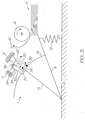
- Fig.s 1 to 5 show one form of the sheet feed mechanism in a diagrammatic form for ease of understanding.
- the sheet feed mechanism 1 is typically used in a larger device such as a printer or the like and would likely have its chassis 2 integrated with that of the printer.
- the sheet feed mechanism 1 lifts the stack of sheets 4 to the picker roller 6 that draws a single sheet into the printer sheet feed path (not shown). Instead of a picker roller, the sheet feed mechanism could also lift the stack toward a suction shoe or other sheet engaging means.
- the stack 4 is inserted into the designated part of the device such as the paper tray of the printer (not shown) while the lift arm 8 is in a lowered position.
- the lift arm 8 is biased upwards by the lift spring 10 but is held in the lowered position by the lock mechanism 12.
- the lock mechanism 12 is at the distal end of the lock arm 14 which is hinged to the chassis 2 at the same hinge axis 16 as the lift arm 8.
- the lock mechanism releasably secures the lock arm 14 to the lift arm 8 via the friction surface 18.
- the lock mechanism 12 abuts the cam 20 to prevent the lock arm 14 and the lift arm 8 from rotating upwards because of the biasing force of the lift spring 10.
- the cam 20 rotates clockwise in response to a paper feed request signal from the printer.
- the cam 20 is positioned within a U-shaped member 22 of the lock mechanism 12.
- the U-shaped member 22 is hinged to the lock arm 14 at the hinge 24.
- the hinge 24 is on the cross piece 26 separating the engagement arm 28 and the disengagement arm 30 on either side of the 'U'.
- the contact foot 32 is attached to the cross piece 26 on the opposite side of the lock hinge 24 to the disengagement arm 30 to form a first class lever.
- Rotating the cam 20 clockwise uses the friction generated between the cam 20 and the engagement arm 28 to urge the contact foot 32 into firmer engagement with the friction surface 18.
- the lift spring 10 pushes the lift arm 8, locking surface 18 and locking arm 14 upwards until the bearing surface 34 abuts the stop 36 on the chassis 2.
- the cam 20 continues to rotate until it contacts the disengagement arm 30. Further rotation presses the disengagement arm 30 towards the bearing surface 34 against the bias of the lock spring 38. This actuates the lever to lift the contact foot 32 out of engagement with the friction surface 18. This unlocks the lift arm 8 from the lock arm 14. This allows the lift spring 10 to elevate the stack 4 until the top-most sheet 40 engages the picker roller 6 and is drawn away from the remainder of the stack.
- the cam 20 continues to rotate and allow the lock spring 38 to push the disengagement arm 30 away from the bearing surface 34. This in turn re-eng ages the contact foot 32 with the friction surface 18 to lock the lock arm 14 and the lift arm 8 together.
- the picker roller 6 continues to draw the top-most sheet 40 from the stack 4.
- the cam 20 rotates into contact with the engagement arm 28 to add to the force with which the contact foot 32 presses onto the friction surface 18.
- the cam 20 also starts to push the engagement arm 28 and therefore the lock arm 14 and lift arm 8 clockwise against the bias of the lift spring 10. Accordingly, the stack 4 starts to drop away from the picker roller 6 before it draws the new top-most sheet 42 off the stack 4.
- Fig. 5 shows the sheet feed mechanism at the completion of its operative cycle.
- the cam 20 rotates until the high point is in contact with the engagement arm 28. This pushes the lock arm 14 and the lift arm 8 back through a set angle of rotation.
- the sack 4 retracts from the picker roller 6 by a predetermined distance. This distance does not alter regardless of the grade (or thickness) of paper in the stack.
- the lift spring 10 need only compress a small amount and therefore the energy consumed by the mechanism as it indexes through the stack is reduced.
- the stack 4 depletes, it weighs less but the spring 10 also decreases its force biasing the stack against the picker roller 6 because it is less compressed. This keeps the force pressing successive top-most sheets against the picker roller substantially uniform.
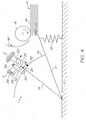
- Fig. 6 is a diagrammatic illustration of another embodiment of the sheet feed mechanism 1.
- the hinged lift arm is replaced with a lift structure 44 that has rectilinear movement instead of rotational.
- the friction surface 18 is on an arm that extends upwardly to be parallel with the direction of travel of the lift structure 44.
- the lock arm 14 is again hinged to the chassis 2 and has a bearing surface 34 with lock spring 38 to bias the contact foot 32 into locking engagement with the friction surface 18.
- the disengagement arm 30, lock hinge 24 and the contact foot 32 again form a first class lever.
- the embodiment shown does not use a U-shaped member but instead configures the lock arm 14 to act as the engagement arm 28 as well.
- the cam 20 contacts the engagement arm 28, it rotates anti-clockwise about the hinge 16.
- the contact foot 32 maintains locking engagement with the friction surface 18 because the spring 38 continues to bias the disengagement arm 30 in a clockwise direction despite the rotation of the engagement arm in an anti clockwise direction.
- the bearing surface 34 rotating anti clockwise tends to maintain the gap bridged by the spring 38 so that the biasing force remains relatively uniform.
- Fig. 6 demonstrates that the invention can adopt many different configurations to suit specific functional requirements and space limitations. Ordinary workers in this field will also appreciate that the cam may be replaced by the solenoid actuator or pneumatic/ hydraulic actuators. Any dual action actuator that contacts the disengagement arm and the engagement arm in succession will be suitable for the purposes of this invention.
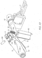
- Fig. 7 shows the invention incorporated into a SOHO printer.
- the printer 46 has a paper feed tray 48 for receiving a ream of blank paper (not shown).
- the paper feed assembly in the printer draws sheets sequentially from the stack placed in the feed tray 48 and directs it then through a C-shaped paper path past a printhead. After printing the pages are collected from a collection tray (not shown) on top of the feed tray 48.
- the lift arm 8 is positioned directly beneath the picker roller 6 with the distal end 50 of the lift arm positioned beneath the leading edge of the stack of sheets (not shown). Initially the lifter arm is held in a fully depressed configuration so that its distal end is flush with the paper support platen 52 in the feed tray 48. The lift arm 8 is forced into this initial position using the lift arm reset lever 54 described in greater detail below.
- Fig. 8 the feed tray and outer housing have been removed for clarity. Again the lift arm 8 is in its lowered initial position so that the distal end 50 lies beneath the leading edge of the paper stack. Coil spring 10 biases the lifter arm upwards about the hinge shaft 16. However the lock mechanism (described below) holds the lifter arm in its initial position until the actuator responds to a request for a sheet.
- Hinge shaft 16 extends from the lifter arm 8 through the lock spring 10 to the locking assembly 56.
- the reset arm 58 On the outer most end of the hinge shaft 16 is the reset arm 58, which is connected to the reset lever 54 via the connecter rod 60.
- the reset arm 58 is mounted to the hinge at shaft 16 via a ratchet engagement that locks the shaft and arm together when rotating clockwise that allows the arm to rotate anti-clockwise while the shaft remains fixed. In this way the user simply depresses the lifter arm reset lever 54 to draw down the reset arm 58 and therefore the lifter arm 8 against bias of the spring 10.
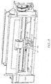
- Fig. 9 Also shown in Fig. 9 , is the cam drive motor 62 with its output worm drive 64 meshed with the drive gear 66 mounted on the cam shaft 68.
- One side of the lock arm 14 is also shown and this is described in greater detail below.
- Fig. 10 shows the feed mechanism with further components removed for clarity.
- the lock arm 14 has two side plates 70 and 72 mounted to the hinge shaft 16. The distal ends of the side plates 70 and 72 are connected by the abutment block 74 positioned to abut the stop 36 secured to the printer chassis. Mounted between the side plates 70 and 72 is the arcuate friction arm 18 and the U-shaped member 22. The side plates 70 and 72 are rotateably mounted to the hinge shaft 16 while the arcuate friction arm 18 is fixed to the shaft 16.
- the cam 20 is shown between the sides of the U-shaped member 22.
- the cam 20 starts rotating clockwise along the engagement arm 28.
- the contact foot is urged into engagement with the arcuate friction arm 18 by any friction between the cam 20 and the engagement arm 28. This is because the contact foot is between side plates 70 and 72 (not shown), to the right of the lock mechanism hinge 24.
- the lock spring 38 also pushes the contact foot into locking engagement.
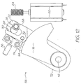
- Fig. 12 shows the locking assembly in the unlocked condition.
- the locking assembly 56 is shown with the side plate 70 removed.
- the cam 20 has rotated to press against the disengagement arm 30 of the U-shaped member 22.
- the cam 20 initially pushes the entire assembly 56 such that it rotates into engagement with the stop 36.
- the cam then rotates the U-shaped member anti-clockwise about the lock mechanism hinge 24. This lifts the contact foot 32, or rather simply unweights it from the arcuate surface on the arcuate friction arm 18.
- Hinge shaft 16 is under the torque provided by the lifter spring 10 (see Fig. 10 ).
- Not shown in Fig. 12 is the elevation of the paper stack by the lifter arm 8 once the arcuate friction arm has been unlocked.
- the lift arm 8 continues to elevate the stack of paper until the top most sheet engages the picker roller 6.
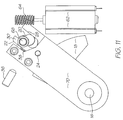
- Fig. 14 shows the locking assembly in its unlocked condition in perspective.
- the U-shaped member 22 is rotated about the lock mechanism hinge 24 such that the disengagement arm 30 compresses the lock spring 38 against the abutment block 74.
- the contact foot 32 is levered out the engagement from the arcuate friction arm 18 to allow the lift arm 8 (see Fig. 10 ) to raise the paper stack.
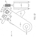
- Fig. 13 shows the locking mechanism 56 as the U-shaped member returns to the lock position.
- the cam 20 continues to rotate clockwise and allows the U-shaped member 22 to also rotate under the action of the lock spring 38. It should be noted that at this stage abutment block 74 is still against the stop 36. Furthermore, the paper stack is still pressed against the picker roller, which would still be drawing the top most sheet from the stack.
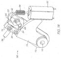
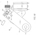
- Fig. 16 shows the locking assembly returned to its initial configuration.
- the cam 20 has rotated back into engagement with the engagement arm 28 to rotate the entire assembly 56 about the hinge shaft 16, a small distance away from the stop 36.
- the hinge shaft 16 is forced to rotate by the cam shaft 20.
- This in turn rotates the lift arm 8 (see Fig. 10 ) then by retracting the paper stack a small distance from the picker roller 6.
- the power load on the cam drive motor 62 is relatively low.
- the distance that the stack retracts from the thicker roller will always remain uniform regardless of the grade of paper inserted in paper feed tray. This improves the versatility of the overall feed mechanism.
Landscapes
- Engineering & Computer Science (AREA)
- Mechanical Engineering (AREA)
- Sheets, Magazines, And Separation Thereof (AREA)
Claims (10)
- Blatteinzugsmechanismus (1), der Folgendes umfasst:ein Gehäuse (2), das dazu konfiguriert ist, einen Blätterstapel (4) zu tragen;ein Oberblatteingriffselement (6) zur Ineingriffnahme des obersten Blatts des Stapels (4) und Bewegen des obersten Blatts in Bezug auf den Rest des Stapels (4) undeine Stapeleingriffsstruktur (8) zur Ineingriffnahme des Stapels und Vorspannen des obersten Blatts gegen das Oberblatteingriffselement (6),wobei der Blatteinzugsmechanismus (1) dadurch gekennzeichnet ist, dass die Stapeleingriffsstruktur (8) eine Reibfläche (18) aufweist, die sich parallel zu der Laufrichtung der Stapeleingriffsstruktur erstreckt;einen Arretiermechanismus (12), der an dem Gehäuse (2) für eine begrenzte relative Bewegung dazu montiert ist, wobei der Arretiermechanismus (12) einen vorgespannten Kontaktfuß (32) zur Ineingriffnahme der Reibfläche (18) aufweist, um die Stapeleingriffsstruktur (8) an dem Arretiermechanismus (12) zur Bewegung damit zu sichern; undeinen Doppelfunktionsaktor (20), der an dem Gehäuse (2) montiert ist, um nacheinander den Kontaktfuß (32) aus dem Eingriff mit der Reibfläche (18) zu lösen und in Eingriff mit dieser zu nehmen, so dass, wenn der Kontaktfuß (32) aus dem Eingriff mit der Reibfläche (18) genommen wird, die Stapeleingriffsstruktur (8) sich in Bezug auf den Arretiermechanismus (12) bewegt, um das oberste Blatt gegen das Oberblatteingriffselement (6) zu drücken, und der Doppelfunktionsaktor dann den Eingriff mit dem Kontaktfuß löst, so dass er die Reibfläche (18) wieder in Eingriff nimmt, und wenn der Doppelfunktionsaktor (20) den Arretiermechanismus (12) in Bezug auf das Gehäuse (2) bewegt, die Stapeleingriffsstruktur (8) sich um eine vorherbestimmte Strecke von dem Element (6) zur Ineingriffnahme des obersten Blatts zurückzieht.
- Blatteinzugsmechanismus nach Anspruch 1, wobei die Stapeleingriffsstruktur ein elastisches Element aufweist, um den Stapel anzuheben, so dass das oberste Blatt des Stapels gegen das Oberblatteingriffselement vorgespannt wird, wobei die Vorspannkraft des elastischen Elements abnimmt, wenn das elastische Element den Stapel hochhebt, so dass, wenn die Dicke und das Gewicht des Stapels abnimmt, die Vorspannkraft ebenfalls abnimmt und das oberste Blatt mit einer im Wesentlichen gleichmäßigen Kraft gegen das Oberblatteingriffselement vorgespannt wird.
- Blatteinzugsmechanismus nach Anspruch 1, wobei der Doppelfunktionsaktor ein Drehnocken ist.
- Blatteinzugsmechanismus nach Anspruch 1, wobei das Oberblatteingriffselement eine gummierte Zuführungswalze ist, die sich dreht, um das oberste Blatt von dem Stapel zu ziehen.
- Blatteinzugsmechanismus nach Anspruch 3, wobei der Arretiermechanismus einen Arretierarm, der drehbar an dem Gehäuse angebracht ist, und einen zweiarmigen Hebel, der an dem Arretierarm drehbar gelagert ist, aufweist, wobei der Kontaktfuß auf einer Seite des Hebels ist und die andere Seite des Hebels für einen Eingriff mit dem Nocken konfiguriert ist, um den Kontaktfuß von der Reibfläche anzuheben.
- Blatteinzugsmechanismus nach Anspruch 5, wobei das Gehäuse weiterhin eine Stoppanordnung umfasst, die nahe dem Nocken ausgebildet ist, und der Arretiermechanismus eine Lagerstruktur aufweist, die fest an dem Arretierarm montiert ist, wobei die Lagerstruktur eine Lageroberfläche zum Anliegen an der Stoppanordnung aufweist, und der Arretiermechanismus weiterhin ein elastisches Element zwischen der Lagerstruktur und dem Arretierarm gegenüber dem Kontaktfuß zum Vorspannen des Kontaktfußes in Eingriff mit der Reibfläche aufweist.
- Blatteinzugsmechanismus nach Anspruch 6, wobei der zweiarmige Hebel im Allgemeinen U-förmig ist, wobei ein erster und ein zweiter Seitenarm durch ein Querstück getrennt sind, und der Nocken zwischen dem ersten und dem zweiten Seitenarm zum abwechselnden Eingriff jedes positioniert ist, wobei der erste Seitenarm den Arretierarm bildet, der den Kontaktfuß betätigt, um die Reibfläche aus dem Eingriff zu lösen, und der zweite Arm die Lageroberfläche bereitstellt, gegen die der Nocken wirkt, um den Arretierarm und die Stapeleingriffsstruktur zu schieben, so dass der Stapel sich von dem Element zur Ineingriffnahme des obersten Blatts zurückzieht.
- Blatteinzugsmechanismus nach Anspruch 7, wobei der zweiarmige Hebel zu dem Arretierarm nahe dem Ende des ersten Seitenarms des Querstücks schwenkt, der Kontaktfuß nahe dem Ende des zweiten Seitenarms des Querstücks positioniert wird und der Nocken sich dreht, so dass jegliche Reibung zwischen dem Nocken und dem zweiten Seitenarm dazu dient, den Kontaktfuß in Eingriff mit der Reibfläche zu treiben.
- Blatteinzugsmechanismus nach Anspruch 5, wobei die Stapeleingriffsstruktur ein Stapelhubarm ist, der drehbar an dem Gehäuse entlang derselben Drehgelenkachse wie der Arretierarm angebracht ist.
- Blatteinzugsmechanismus nach Anspruch 9, wobei die Reibfläche ein bogenförmiger Abschnitt ist, der einen Krümmungsmittelpunkt auf der Drehgelenkachse des Stapelhubarms aufweist und zur Drehung damit befestigt ist.
Applications Claiming Priority (2)
| Application Number | Priority Date | Filing Date | Title |
|---|---|---|---|
| US11/482,981 US7571906B2 (en) | 2006-07-10 | 2006-07-10 | Sheet feed mechanism |
| PCT/AU2007/000591 WO2008006138A1 (en) | 2006-07-10 | 2007-05-07 | Sheet feed mechanism |
Publications (3)
| Publication Number | Publication Date |
|---|---|
| EP2043933A1 EP2043933A1 (de) | 2009-04-08 |
| EP2043933A4 EP2043933A4 (de) | 2012-02-08 |
| EP2043933B1 true EP2043933B1 (de) | 2016-07-27 |
Family
ID=38918429
Family Applications (1)
| Application Number | Title | Priority Date | Filing Date |
|---|---|---|---|
| EP07718838.1A Not-in-force EP2043933B1 (de) | 2006-07-10 | 2007-05-07 | Mechanismus zur zuführung von flächengebilden |
Country Status (4)
| Country | Link |
|---|---|
| US (3) | US7571906B2 (de) |
| EP (1) | EP2043933B1 (de) |
| JP (1) | JP4845155B2 (de) |
| WO (1) | WO2008006138A1 (de) |
Families Citing this family (2)
| Publication number | Priority date | Publication date | Assignee | Title |
|---|---|---|---|---|
| US7571906B2 (en) * | 2006-07-10 | 2009-08-11 | Silverbrook Research Pty Ltd | Sheet feed mechanism |
| JP5743494B2 (ja) * | 2010-11-04 | 2015-07-01 | キヤノン株式会社 | 記録材供給装置、及び画像形成装置 |
Family Cites Families (16)
| Publication number | Priority date | Publication date | Assignee | Title |
|---|---|---|---|---|
| US4418903A (en) * | 1978-04-20 | 1983-12-06 | Savin Corporation | Large capacity combination magazine and sheet feeder for copying machines |
| DE3151004A1 (de) * | 1981-12-23 | 1983-08-04 | Agfa-Gevaert Ag, 5090 Leverkusen | Blattvereinzelungseinrichtung |
| JPS60128139A (ja) * | 1983-12-14 | 1985-07-09 | Fujitsu Ltd | 給紙機構 |
| NL8601261A (nl) | 1986-05-20 | 1987-12-16 | Oce Nederland Bv | Inrichting voor het afvoeren van vellen vanaf de bovenkant van een stapel. |
| JPH0562125A (ja) | 1991-09-03 | 1993-03-12 | Sony Corp | 薄膜磁気ヘツドの製造方法 |
| US5358230A (en) * | 1992-04-24 | 1994-10-25 | Canon Kabushiki Kaisha | Sheet supplying apparatus |
| US6315282B2 (en) * | 1997-06-27 | 2001-11-13 | Hewlett-Packard Company | Apparatus and a method for picking multiple-sized media sheets |
| US6485014B1 (en) * | 1999-03-17 | 2002-11-26 | Avision Inc. | Automatic paper feeding mechanism |
| TW500666B (en) * | 2000-03-03 | 2002-09-01 | Benq Corp | Paper feeding system with paper separation mechanism and paper stop mechanism |
| JP2002019977A (ja) * | 2000-07-03 | 2002-01-23 | Toshiba Tec Corp | 給紙装置 |
| TW541252B (en) * | 2000-12-01 | 2003-07-11 | Benq Corp | Automatic paper feeder capable of performing normal pick up operation for paper sheets with different thickness |
| JP3720706B2 (ja) * | 2000-12-18 | 2005-11-30 | キヤノン株式会社 | シート給送装置及びこれを備えた画像形成装置並びに画像読取装置 |
| JP3856116B2 (ja) * | 2001-12-20 | 2006-12-13 | 富士ゼロックス株式会社 | シート供給装置及びこれを用いた画像形成装置 |
| KR100431006B1 (ko) * | 2002-05-10 | 2004-05-12 | 삼성전자주식회사 | 프린팅기기의 용지 카트리지 |
| JP4104399B2 (ja) * | 2002-08-28 | 2008-06-18 | シャープ株式会社 | 給紙装置 |
| US7571906B2 (en) * | 2006-07-10 | 2009-08-11 | Silverbrook Research Pty Ltd | Sheet feed mechanism |
-
2006
- 2006-07-10 US US11/482,981 patent/US7571906B2/en not_active Expired - Fee Related
-
2007
- 2007-05-07 WO PCT/AU2007/000591 patent/WO2008006138A1/en not_active Ceased
- 2007-05-07 EP EP07718838.1A patent/EP2043933B1/de not_active Not-in-force
- 2007-05-07 JP JP2009518677A patent/JP4845155B2/ja not_active Expired - Fee Related
-
2009
- 2009-07-19 US US12/505,520 patent/US7726647B2/en not_active Expired - Fee Related
-
2010
- 2010-05-19 US US12/783,509 patent/US8118300B2/en active Active
Also Published As
| Publication number | Publication date |
|---|---|
| US20100225049A1 (en) | 2010-09-09 |
| JP4845155B2 (ja) | 2011-12-28 |
| EP2043933A4 (de) | 2012-02-08 |
| US20090278300A1 (en) | 2009-11-12 |
| US7571906B2 (en) | 2009-08-11 |
| JP2009542554A (ja) | 2009-12-03 |
| WO2008006138A1 (en) | 2008-01-17 |
| US20080006986A1 (en) | 2008-01-10 |
| EP2043933A1 (de) | 2009-04-08 |
| US8118300B2 (en) | 2012-02-21 |
| US7726647B2 (en) | 2010-06-01 |
Similar Documents
| Publication | Publication Date | Title |
|---|---|---|
| US6257569B1 (en) | Apparatus and method for delivery of sheet media to a printer | |
| JP3267593B2 (ja) | 用紙残量感知方法 | |
| EP2043933B1 (de) | Mechanismus zur zuführung von flächengebilden | |
| TW500666B (en) | Paper feeding system with paper separation mechanism and paper stop mechanism | |
| EP1435297B1 (de) | Drucker | |
| JP4520071B2 (ja) | 給紙装置および画像形成装置 | |
| JPH0126667Y2 (de) | ||
| JP3909160B2 (ja) | 複数の媒体シート・スタックのための複数スタック選択機 | |
| JP2547978B2 (ja) | シート材給送装置 | |
| JP4231617B2 (ja) | 給紙機構 | |
| AU743178B2 (en) | Paper-feeding apparatus | |
| US20040201163A1 (en) | Media positioning at a picking location | |
| JP3940262B2 (ja) | 給紙装置、及び画像形成装置 | |
| JPH11217124A (ja) | 用紙供給装置 | |
| US6305683B1 (en) | Front loading type of automatic paper feeding apparatus for preventing paper from being skewed | |
| JP2010202378A (ja) | 給紙トレイ及び画像形成装置 | |
| JP3362827B2 (ja) | 給紙装置 | |
| KR20000050841A (ko) | 인쇄기기의 노크-업 플레이트 리프팅장치 | |
| JP4260709B2 (ja) | 給紙装置 | |
| JPH0415721Y2 (de) | ||
| KR100529342B1 (ko) | 잉크젯 프린터 및 잉크젯 프린터의 용지이송방법 | |
| JP2000085989A (ja) | 給紙装置 | |
| JP2009062114A (ja) | シート供給装置、及び画像形成装置 | |
| JP3637240B2 (ja) | 画像形成装置の給紙装置 | |
| JPH0611624B2 (ja) | カセットケースを用いる給紙装置 |
Legal Events
| Date | Code | Title | Description |
|---|---|---|---|
| PUAI | Public reference made under article 153(3) epc to a published international application that has entered the european phase |
Free format text: ORIGINAL CODE: 0009012 |
|
| 17P | Request for examination filed |
Effective date: 20090206 |
|
| AK | Designated contracting states |
Kind code of ref document: A1 Designated state(s): AT BE BG CH CY CZ DE DK EE ES FI FR GB GR HU IE IS IT LI LT LU LV MC MT NL PL PT RO SE SI SK TR |
|
| AX | Request for extension of the european patent |
Extension state: AL BA HR MK RS |
|
| A4 | Supplementary search report drawn up and despatched |
Effective date: 20120112 |
|
| RIC1 | Information provided on ipc code assigned before grant |
Ipc: B65H 1/14 20060101ALI20120105BHEP Ipc: B65H 5/06 20060101ALI20120105BHEP Ipc: B65H 3/06 20060101ALI20120105BHEP Ipc: B65H 1/04 20060101AFI20120105BHEP |
|
| DAX | Request for extension of the european patent (deleted) | ||
| RAP1 | Party data changed (applicant data changed or rights of an application transferred) |
Owner name: ZAMTEC LIMITED |
|
| RAP1 | Party data changed (applicant data changed or rights of an application transferred) |
Owner name: MEMJET TECHNOLOLGY LIMITED |
|
| RAP1 | Party data changed (applicant data changed or rights of an application transferred) |
Owner name: MEMJET TECHNOLOGY LIMITED |
|
| 17Q | First examination report despatched |
Effective date: 20151012 |
|
| GRAP | Despatch of communication of intention to grant a patent |
Free format text: ORIGINAL CODE: EPIDOSNIGR1 |
|
| INTG | Intention to grant announced |
Effective date: 20160224 |
|
| GRAS | Grant fee paid |
Free format text: ORIGINAL CODE: EPIDOSNIGR3 |
|
| GRAA | (expected) grant |
Free format text: ORIGINAL CODE: 0009210 |
|
| AK | Designated contracting states |
Kind code of ref document: B1 Designated state(s): AT BE BG CH CY CZ DE DK EE ES FI FR GB GR HU IE IS IT LI LT LU LV MC MT NL PL PT RO SE SI SK TR |
|
| REG | Reference to a national code |
Ref country code: GB Ref legal event code: FG4D |
|
| REG | Reference to a national code |
Ref country code: CH Ref legal event code: EP |
|
| REG | Reference to a national code |
Ref country code: AT Ref legal event code: REF Ref document number: 815628 Country of ref document: AT Kind code of ref document: T Effective date: 20160815 |
|
| REG | Reference to a national code |
Ref country code: IE Ref legal event code: FG4D |
|
| REG | Reference to a national code |
Ref country code: DE Ref legal event code: R096 Ref document number: 602007047171 Country of ref document: DE |
|
| REG | Reference to a national code |
Ref country code: LT Ref legal event code: MG4D |
|
| REG | Reference to a national code |
Ref country code: NL Ref legal event code: MP Effective date: 20160727 |
|
| REG | Reference to a national code |
Ref country code: AT Ref legal event code: MK05 Ref document number: 815628 Country of ref document: AT Kind code of ref document: T Effective date: 20160727 |
|
| PG25 | Lapsed in a contracting state [announced via postgrant information from national office to epo] |
Ref country code: NL Free format text: LAPSE BECAUSE OF FAILURE TO SUBMIT A TRANSLATION OF THE DESCRIPTION OR TO PAY THE FEE WITHIN THE PRESCRIBED TIME-LIMIT Effective date: 20160727 Ref country code: IS Free format text: LAPSE BECAUSE OF FAILURE TO SUBMIT A TRANSLATION OF THE DESCRIPTION OR TO PAY THE FEE WITHIN THE PRESCRIBED TIME-LIMIT Effective date: 20161127 Ref country code: FI Free format text: LAPSE BECAUSE OF FAILURE TO SUBMIT A TRANSLATION OF THE DESCRIPTION OR TO PAY THE FEE WITHIN THE PRESCRIBED TIME-LIMIT Effective date: 20160727 Ref country code: IT Free format text: LAPSE BECAUSE OF FAILURE TO SUBMIT A TRANSLATION OF THE DESCRIPTION OR TO PAY THE FEE WITHIN THE PRESCRIBED TIME-LIMIT Effective date: 20160727 Ref country code: LT Free format text: LAPSE BECAUSE OF FAILURE TO SUBMIT A TRANSLATION OF THE DESCRIPTION OR TO PAY THE FEE WITHIN THE PRESCRIBED TIME-LIMIT Effective date: 20160727 |
|
| PG25 | Lapsed in a contracting state [announced via postgrant information from national office to epo] |
Ref country code: PL Free format text: LAPSE BECAUSE OF FAILURE TO SUBMIT A TRANSLATION OF THE DESCRIPTION OR TO PAY THE FEE WITHIN THE PRESCRIBED TIME-LIMIT Effective date: 20160727 Ref country code: GR Free format text: LAPSE BECAUSE OF FAILURE TO SUBMIT A TRANSLATION OF THE DESCRIPTION OR TO PAY THE FEE WITHIN THE PRESCRIBED TIME-LIMIT Effective date: 20161028 Ref country code: BE Free format text: LAPSE BECAUSE OF FAILURE TO SUBMIT A TRANSLATION OF THE DESCRIPTION OR TO PAY THE FEE WITHIN THE PRESCRIBED TIME-LIMIT Effective date: 20160727 Ref country code: LV Free format text: LAPSE BECAUSE OF FAILURE TO SUBMIT A TRANSLATION OF THE DESCRIPTION OR TO PAY THE FEE WITHIN THE PRESCRIBED TIME-LIMIT Effective date: 20160727 Ref country code: AT Free format text: LAPSE BECAUSE OF FAILURE TO SUBMIT A TRANSLATION OF THE DESCRIPTION OR TO PAY THE FEE WITHIN THE PRESCRIBED TIME-LIMIT Effective date: 20160727 Ref country code: SE Free format text: LAPSE BECAUSE OF FAILURE TO SUBMIT A TRANSLATION OF THE DESCRIPTION OR TO PAY THE FEE WITHIN THE PRESCRIBED TIME-LIMIT Effective date: 20160727 Ref country code: ES Free format text: LAPSE BECAUSE OF FAILURE TO SUBMIT A TRANSLATION OF THE DESCRIPTION OR TO PAY THE FEE WITHIN THE PRESCRIBED TIME-LIMIT Effective date: 20160727 Ref country code: PT Free format text: LAPSE BECAUSE OF FAILURE TO SUBMIT A TRANSLATION OF THE DESCRIPTION OR TO PAY THE FEE WITHIN THE PRESCRIBED TIME-LIMIT Effective date: 20161128 |
|
| PG25 | Lapsed in a contracting state [announced via postgrant information from national office to epo] |
Ref country code: EE Free format text: LAPSE BECAUSE OF FAILURE TO SUBMIT A TRANSLATION OF THE DESCRIPTION OR TO PAY THE FEE WITHIN THE PRESCRIBED TIME-LIMIT Effective date: 20160727 Ref country code: RO Free format text: LAPSE BECAUSE OF FAILURE TO SUBMIT A TRANSLATION OF THE DESCRIPTION OR TO PAY THE FEE WITHIN THE PRESCRIBED TIME-LIMIT Effective date: 20160727 |
|
| REG | Reference to a national code |
Ref country code: DE Ref legal event code: R097 Ref document number: 602007047171 Country of ref document: DE |
|
| REG | Reference to a national code |
Ref country code: FR Ref legal event code: PLFP Year of fee payment: 11 |
|
| PG25 | Lapsed in a contracting state [announced via postgrant information from national office to epo] |
Ref country code: SK Free format text: LAPSE BECAUSE OF FAILURE TO SUBMIT A TRANSLATION OF THE DESCRIPTION OR TO PAY THE FEE WITHIN THE PRESCRIBED TIME-LIMIT Effective date: 20160727 Ref country code: DK Free format text: LAPSE BECAUSE OF FAILURE TO SUBMIT A TRANSLATION OF THE DESCRIPTION OR TO PAY THE FEE WITHIN THE PRESCRIBED TIME-LIMIT Effective date: 20160727 Ref country code: CZ Free format text: LAPSE BECAUSE OF FAILURE TO SUBMIT A TRANSLATION OF THE DESCRIPTION OR TO PAY THE FEE WITHIN THE PRESCRIBED TIME-LIMIT Effective date: 20160727 Ref country code: BG Free format text: LAPSE BECAUSE OF FAILURE TO SUBMIT A TRANSLATION OF THE DESCRIPTION OR TO PAY THE FEE WITHIN THE PRESCRIBED TIME-LIMIT Effective date: 20161027 |
|
| PLBE | No opposition filed within time limit |
Free format text: ORIGINAL CODE: 0009261 |
|
| STAA | Information on the status of an ep patent application or granted ep patent |
Free format text: STATUS: NO OPPOSITION FILED WITHIN TIME LIMIT |
|
| 26N | No opposition filed |
Effective date: 20170502 |
|
| PGFP | Annual fee paid to national office [announced via postgrant information from national office to epo] |
Ref country code: IE Payment date: 20170628 Year of fee payment: 11 Ref country code: IE Payment date: 20170530 Year of fee payment: 11 |
|
| PG25 | Lapsed in a contracting state [announced via postgrant information from national office to epo] |
Ref country code: SI Free format text: LAPSE BECAUSE OF FAILURE TO SUBMIT A TRANSLATION OF THE DESCRIPTION OR TO PAY THE FEE WITHIN THE PRESCRIBED TIME-LIMIT Effective date: 20160727 Ref country code: LU Free format text: LAPSE BECAUSE OF NON-PAYMENT OF DUE FEES Effective date: 20170531 |
|
| REG | Reference to a national code |
Ref country code: CH Ref legal event code: PL |
|
| PG25 | Lapsed in a contracting state [announced via postgrant information from national office to epo] |
Ref country code: MC Free format text: LAPSE BECAUSE OF FAILURE TO SUBMIT A TRANSLATION OF THE DESCRIPTION OR TO PAY THE FEE WITHIN THE PRESCRIBED TIME-LIMIT Effective date: 20160727 |
|
| PG25 | Lapsed in a contracting state [announced via postgrant information from national office to epo] |
Ref country code: CH Free format text: LAPSE BECAUSE OF NON-PAYMENT OF DUE FEES Effective date: 20170531 Ref country code: LI Free format text: LAPSE BECAUSE OF NON-PAYMENT OF DUE FEES Effective date: 20170531 |
|
| PG25 | Lapsed in a contracting state [announced via postgrant information from national office to epo] |
Ref country code: LU Free format text: LAPSE BECAUSE OF NON-PAYMENT OF DUE FEES Effective date: 20170507 |
|
| PG25 | Lapsed in a contracting state [announced via postgrant information from national office to epo] |
Ref country code: MT Free format text: LAPSE BECAUSE OF NON-PAYMENT OF DUE FEES Effective date: 20170507 |
|
| REG | Reference to a national code |
Ref country code: IE Ref legal event code: MM4A |
|
| PG25 | Lapsed in a contracting state [announced via postgrant information from national office to epo] |
Ref country code: FR Free format text: LAPSE BECAUSE OF NON-PAYMENT OF DUE FEES Effective date: 20180531 Ref country code: IE Free format text: LAPSE BECAUSE OF NON-PAYMENT OF DUE FEES Effective date: 20180507 |
|
| PG25 | Lapsed in a contracting state [announced via postgrant information from national office to epo] |
Ref country code: HU Free format text: LAPSE BECAUSE OF FAILURE TO SUBMIT A TRANSLATION OF THE DESCRIPTION OR TO PAY THE FEE WITHIN THE PRESCRIBED TIME-LIMIT; INVALID AB INITIO Effective date: 20070507 |
|
| PG25 | Lapsed in a contracting state [announced via postgrant information from national office to epo] |
Ref country code: CY Free format text: LAPSE BECAUSE OF NON-PAYMENT OF DUE FEES Effective date: 20160727 |
|
| PG25 | Lapsed in a contracting state [announced via postgrant information from national office to epo] |
Ref country code: TR Free format text: LAPSE BECAUSE OF FAILURE TO SUBMIT A TRANSLATION OF THE DESCRIPTION OR TO PAY THE FEE WITHIN THE PRESCRIBED TIME-LIMIT Effective date: 20160727 |
|
| PGFP | Annual fee paid to national office [announced via postgrant information from national office to epo] |
Ref country code: DE Payment date: 20210527 Year of fee payment: 15 |
|
| PGFP | Annual fee paid to national office [announced via postgrant information from national office to epo] |
Ref country code: GB Payment date: 20210527 Year of fee payment: 15 |
|
| REG | Reference to a national code |
Ref country code: DE Ref legal event code: R119 Ref document number: 602007047171 Country of ref document: DE |
|
| GBPC | Gb: european patent ceased through non-payment of renewal fee |
Effective date: 20220507 |
|
| PG25 | Lapsed in a contracting state [announced via postgrant information from national office to epo] |
Ref country code: GB Free format text: LAPSE BECAUSE OF NON-PAYMENT OF DUE FEES Effective date: 20220507 Ref country code: DE Free format text: LAPSE BECAUSE OF NON-PAYMENT OF DUE FEES Effective date: 20221201 |