EP2044285B1 - Procédé et dispositif pour la commande directionnelle d'une machine de forage de roche - Google Patents
Procédé et dispositif pour la commande directionnelle d'une machine de forage de roche Download PDFInfo
- Publication number
- EP2044285B1 EP2044285B1 EP07793920.5A EP07793920A EP2044285B1 EP 2044285 B1 EP2044285 B1 EP 2044285B1 EP 07793920 A EP07793920 A EP 07793920A EP 2044285 B1 EP2044285 B1 EP 2044285B1
- Authority
- EP
- European Patent Office
- Prior art keywords
- steering
- drill bit
- feeding rod
- axis
- drilling unit
- Prior art date
- Legal status (The legal status is an assumption and is not a legal conclusion. Google has not performed a legal analysis and makes no representation as to the accuracy of the status listed.)
- Active
Links
Images

Classifications
-
- E—FIXED CONSTRUCTIONS
- E21—EARTH OR ROCK DRILLING; MINING
- E21B—EARTH OR ROCK DRILLING; OBTAINING OIL, GAS, WATER, SOLUBLE OR MELTABLE MATERIALS OR A SLURRY OF MINERALS FROM WELLS
- E21B7/00—Special methods or apparatus for drilling
- E21B7/04—Directional drilling
- E21B7/06—Deflecting the direction of boreholes
- E21B7/068—Deflecting the direction of boreholes drilled by a down-hole drilling motor
-
- E—FIXED CONSTRUCTIONS
- E21—EARTH OR ROCK DRILLING; MINING
- E21B—EARTH OR ROCK DRILLING; OBTAINING OIL, GAS, WATER, SOLUBLE OR MELTABLE MATERIALS OR A SLURRY OF MINERALS FROM WELLS
- E21B10/00—Drill bits
- E21B10/26—Drill bits with leading portion, i.e. drill bits with a pilot cutter; Drill bits for enlarging the borehole, e.g. reamers
-
- E—FIXED CONSTRUCTIONS
- E21—EARTH OR ROCK DRILLING; MINING
- E21B—EARTH OR ROCK DRILLING; OBTAINING OIL, GAS, WATER, SOLUBLE OR MELTABLE MATERIALS OR A SLURRY OF MINERALS FROM WELLS
- E21B4/00—Drives for drilling, used in the borehole
- E21B4/04—Electric drives
-
- E—FIXED CONSTRUCTIONS
- E21—EARTH OR ROCK DRILLING; MINING
- E21B—EARTH OR ROCK DRILLING; OBTAINING OIL, GAS, WATER, SOLUBLE OR MELTABLE MATERIALS OR A SLURRY OF MINERALS FROM WELLS
- E21B7/00—Special methods or apparatus for drilling
- E21B7/04—Directional drilling
- E21B7/06—Deflecting the direction of boreholes
- E21B7/067—Deflecting the direction of boreholes with means for locking sections of a pipe or of a guide for a shaft in angular relation, e.g. adjustable bent sub
Definitions
- This invention relates to a method for the directional control of a drilling unit of a rock-drilling machine, the method comprising the steps of providing a drilling unit of the rock drilling machine, and locating the drilling unit in a borehole, the drilling unit comprising at least a pilot drill bit or an underreamer drill bit, and in which the drill bit(s) is/are driven by an electric motor via a gearbox near the drill bit(s).
- the drill bit(s) is/are moved into the rock by means of a feeding rod extending from a feeding machine at the outside of the borehole, the drill bit(s), gearbox and motor being pivoted in a controlled manner about a steering axis which is approximately perpendicular to the longitudinal axis of the feeding rod.
- the invention also includes a device for practising the method.
- rock drilling in which the borehole has too small a cross- section for persons to be in the borehole, it is known to use a rock-drilling machine which is provided with one pilot drill bit and at least one underreamer drill bit located behind the pilot drill bit relative to the direction of drilling.
- Rock-drilling machines of this kind are controlled directionally by the axis of rotation of the drill bit being given a fixed angle relative to the longitudinal axis of the feeding rod. This causes the drill bits to drill at an angle relative to the feeding rod.
- the desired direction of drilling is achieved by rotating the feeding rod about the centre axis of the borehole until the drill bits drill in the desired direction.
- the method has the effect of the borehole exhibiting a partially considerable helical shape, which makes further movement of the drill bits into the borehole difficult, especially when relatively long boreholes are involved.
- the helical shape can also make subsequent further underreaming of the borehole difficult.
- the invention has for its object to remedy or reduce at least one of the drawbacks of the prior art.
- the directional control of a drilling unit in accordance with the invention the drilling unit of a rock-drilling machine being locatable in a borehole, the drilling unit including at least a pilot drill bit or an underreamer drill bit, the drill bit(s) being driven by an electric motor via a gearbox, and the drill bit(s) being moved into the rock by means of a feeding rod extending from a feeding machine at the outside of the borehole, is characterized by the drilling unit being provided with a steering joint comprising a steering axle, the centre axis of the steering axle coinciding with a steering axis, the steering joint being connected to an intermediate housing connected to the feeding rod by means of an axle mount, and the drill bit(s), gearbox and motor being pivoted in a controlled manner about the steering axis, the steering axis being in a fixed position relative the intermediate housing and approximately perpendicular to the centre axis of the feeding rod.
- the position of the drilling unit is monitored by a control system, the rotational angle of the drilling unit about the centre axis of the feeding rod and the steering angle between the drill bit(s) and the feeding rod being adjusted in accordance with the desired value. Otherwise, the feeding rod does not rotate beyond the springing rotation caused by the torque of the drill bit(s).
- the steering axis is located between the drill bit(s) and a support at the inner end portion of the feeding rod.
- the steering joint is typically connected to a bearing housing, which is connected to the motor.
- An actuator is connected between the axle mount and the bearing housing and is arranged to pivot the bearing housing about the steering axle and relative to the axle mount.
- the actuator is supplied with pressurized fluid from a circulation pump via a control valve.
- the control valve is controlled by the control system on the basis of the measured position of the drilling unit.
- the angle between the centre axis of the drill bit(s) and the centre axis of the feeding rod is monitored by means of a transmitter.
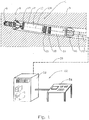
- the reference numeral 1 indicates a drilling unit of a rock-drilling machine not shown in its entirety.
- the drilling unit 1 is located in a borehole 2 in the rock 3 and is connected by means of a feeding rod 4 to a feeding machine, not shown, located outside the borehole 2.
- the drilling unit 1 includes a pilot drill bit 6 and an underreamer drill bit 8, which is located somewhat behind the pilot drill bit 6.
- the drill bits 6 and 8 are driven by an electric motor 10 via a gearbox 12.
- the motor 10 is connected, together with the gearbox 12 and drill bits 6 and 8, to a steering joint 13 connected in turn to an intermediate housing 14. At its opposite end portion the intermediate housing 14 is fixedly connected to a support 16 and to the inner end portion of the feeding rod 4.
- the drilling unit 1 bears on the borehole 2 by the drill bits 6, 8 and by the support 16.
- the pivot axis of the steering joint 13 forms a steering axis 18.
- a power and control cable 20 extends along the borehole 2 from a control system 22 located outside the borehole 2 in to the drilling unit 1.
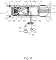
- the steering joint 13 is connected to the intermediate housing 14 by means of an axle mount 28, see figure 2 , supporting a steering axle 30.
- the centre axis of the steering axle 30 coincides with the steering axis 18.
- a bearing housing 32 which is bearingly rotatable about the steering axle 30, is connected to the motor 10.
- the axle mount 28, steering axle 30 and bearing housing 32 form the steering joint 13.
- the torque of the motor 10 is transmitted via the steering joint 13, intermediate housing 14 and feeding rod 4 to the feeding machine not shown.
- a counter arm 34 which is connected to the axle mount 28, projects somewhat into the intermediate housing 14.
- a steering arm 36 connected to the bearing housing 32 also projects somewhat into the intermediate housing 14.
- An actuator 38 here in the form of a hydraulic cylinder, is connected between the free end portions of the counter arm 34 and the steering arm 36.
- Movement of the piston rod 40 of the actuator 38 causes the steering arm 36 together with the bearing housing 32, motor 10, gearbox 12 and drill bits 6 and 8 to be pivoted about the steering axis 18, so that the angle ⁇ between the centre axis 24 of the drill bits 6, 8 and the centre axis 26 of the feeding rod 4 changes, see figure 3 .
- the actuator 38 is connected to a control valve 42 by means of pipe connections 44.
- the coupling is shown schematically in figure 2 .
- the control valve 42 is supplied with pressurized fluid from a circulation pump 46 via circulation pipes 48.
- the circulation pump 46 normally circulates fluid to the support of the drill bits 6, 8, indicated here schematically by the reference numeral 50, via a tank 51.
- the control valve 42 is controlled and the circulation pump 46 is supplied with energy by means of wires, not shown, via the power and control cable 20.
- the control system 22 includes a control cabinet 52 with necessary components and a control console 54. From the control console 54 the position, power consumption and operating temperature, for example, of the rock-drilling machine may be monitored in a manner known per se.
- the feeding rod 4 is rotated, if necessary, about its centre axis 26 until the steering axis 18 takes the desired direction.
- the control valve 42 is activated so that the piston rod 40 is moved in the actuator 38 until the angle ⁇ takes the desired value, which is fed back from a transmitter 56 at the actuator 38.
- the circulation pump 46 and control valve 42 is disposed in the intermediate housing 14.
- the intermediate housing 14 may form a fluid reservoir for pressurized fluid.
- Flushing water for cleaning the drill bits 6, 8 is supplied via the feeding rod 4, flowing via conduit elements, not shown, through the intermediate housing 14, steering joint 13, motor 10, gearbox 12 up to the drill bits 6, 8.
Landscapes
- Engineering & Computer Science (AREA)
- Life Sciences & Earth Sciences (AREA)
- Geology (AREA)
- Mining & Mineral Resources (AREA)
- Physics & Mathematics (AREA)
- Environmental & Geological Engineering (AREA)
- Fluid Mechanics (AREA)
- General Life Sciences & Earth Sciences (AREA)
- Geochemistry & Mineralogy (AREA)
- Mechanical Engineering (AREA)
- Earth Drilling (AREA)
Claims (9)
- Un procédé pour la commande directionnelle d'une unité de forage (1) d'une machine de forage de roche, le procédé comprenant les étapes de :fournir une unité de forage (1) de la machine de forage de roche, etlocaliser l'unité de forage (1) dans un trou de forage (2),l'unité de forage comprenant au moins un foret pilote (6) ou un foret élargisseur (8),le ou les forêts (6, 8) étant entraînés par un moteur électrique (10) par l'intermédiaire d'une boîte à engrenages (12), etle ou les forêts (6, 8) étant déplacés dans la roche (3) au moyen d'une tige d'avance (4) qui s'étend à partir d'une machine d'avance à l'extérieur du trou de forage (2), caractérisé en ce que le procédé comprend en outre les étapes de :pivoter le ou les forêts (6, 8), la boîte à engrenages (12) et le moteur (10) de manière contrôlée autour d'un axe de direction (18), l'unité de forage (1) étant munie d'un joint de direction (13) incluant un essieu de direction (30), le joint de direction (13) étant connecté à un boîtier intermédiaire (14) connecté à une tige d'avance (4) au moyen d'une monture d'essieu (28), un axe central dudit essieu de direction (30) formant l'axe de direction (18) coïncidant avec l'essieu de direction (30), l'axe de direction (18) étant dans une position fixe par rapport au boîtier intermédiaire (14) et approximativement perpendiculaire à l'axe central (26) de la tige d'avance (4).
- Le procédé selon la revendication 1, caractérisé en ce que le procédé comprend en outre les étapes de :surveiller la position de l'unité de forage (1) par l'intermédiaire d'un système de contrôle (22), après quoi l'angle rotationnel de l'unité de forage (1) autour de l'axe central (26) de la tige d'avance (4) et un angle α entre l'axe central (24) du foret (6, 8) et l'axe central (26) de la tige d'avance (4) est ajusté selon la valeur désirée.
- Un dispositif de contrôle pour une machine de forage de roche, qui est localisable dans un trou de forage, le dispositif de contrôle comprenantune unité de forage (1) comprenant au moins un foret de centrage (6) ou un foret élargisseur (8), et oùle ou les forêts (6, 8) est/sont entrainé/s par un moteur électronique (10) par l'intermédiaire d'une boîte à engrenage (12), etle ou les forêts (6, 8) est/sont déplaçable/s dans la roche (3) au moyen d'une tige d'avance (4) s'étendant à partir d'une machine d'avance à l'extérieur du trou de forage (2), caractérisé en ce quel'unité de forage (1) est munie d'un joint de direction (13) comprenant un essieu de direction (30), l'axe central de l'essieu d'avance (30) coïncidant avec l'essieu de direction (18),le joint de direction (30) est connecté à un boîtier intermédiaire (14) connecté à une tige d'avance (4) au moyen d'une monture d'essieu (28), et le ou les forêts (6, 8), la boite à engrenage (12) et le moteur (10) peuvent d'être pivotés autour de l'axe de direction (18), et où l'essieu de direction (18) est fixé par rapport au boîtier intermédiaire (14) et est approximativement perpendiculaire à l'axe central (26) de la tige d'avance (4).
- Le dispositif selon la revendication 3, caractérisé en ce que l'essieu de direction (18) est situé entre le ou les forêts (6, 8) et une monture (16) au niveau de la partie terminale intérieure de la tige d'avance (4).
- Le dispositif selon la revendication 3, caractérisé en ce que le joint de direction (13) est connecté au moteur (10) au moyen d'un boîtier de roulement (32).
- Le dispositif selon la revendication 5, caractérisé en ce que un actuateur (38) est connecté entre la monture d'essieu (28) et le boîtier de roulement (32) et est arrangé pour pivoter le boîtier de roulement (32) par rapport à la monture d'essieu (28) autour de l'axe de direction (30).
- Le dispositif selon la revendication 6, caractérisé en ce que l'actuateur (38) est alimenté avec du fluide sous pression à partir d'une pompe à circulation (46) à travers une soupape de contrôle (42).
- Le dispositif selon la revendication 7, caractérisé en ce que la soupape de contrôle (42) est contrôlée par un système de contrôle (22) à base de la position mesurée de l'unité de forage (1).
- Le dispositif selon la revendication 8, caractérisé en ce que un angle (α) entre l'axe central (24) du forêt (6, 8) et l'axe central (26) de la tige d'avance (4) est surveillé au moyen d'un transmetteur (56).
Applications Claiming Priority (2)
| Application Number | Priority Date | Filing Date | Title |
|---|---|---|---|
| NO20063402A NO326032B1 (no) | 2006-07-24 | 2006-07-24 | Fremgangsmåte og anordning for retningsstyring av bergboremaskin |
| PCT/NO2007/000268 WO2008013458A1 (fr) | 2006-07-24 | 2007-07-12 | Procédé et dispositif pour la commande directionnelle d'une machine de forage de roche |
Publications (3)
| Publication Number | Publication Date |
|---|---|
| EP2044285A1 EP2044285A1 (fr) | 2009-04-08 |
| EP2044285A4 EP2044285A4 (fr) | 2015-06-17 |
| EP2044285B1 true EP2044285B1 (fr) | 2017-06-21 |
Family
ID=38981711
Family Applications (1)
| Application Number | Title | Priority Date | Filing Date |
|---|---|---|---|
| EP07793920.5A Active EP2044285B1 (fr) | 2006-07-24 | 2007-07-12 | Procédé et dispositif pour la commande directionnelle d'une machine de forage de roche |
Country Status (7)
| Country | Link |
|---|---|
| US (1) | US7984769B2 (fr) |
| EP (1) | EP2044285B1 (fr) |
| AU (1) | AU2007277483B2 (fr) |
| BR (1) | BRPI0714680B1 (fr) |
| CA (1) | CA2658201C (fr) |
| NO (1) | NO326032B1 (fr) |
| WO (1) | WO2008013458A1 (fr) |
Families Citing this family (10)
| Publication number | Priority date | Publication date | Assignee | Title |
|---|---|---|---|---|
| GB2458909B (en) * | 2008-04-01 | 2013-03-06 | Antech Ltd | Directional well drilling |
| NO333816B1 (no) * | 2008-06-05 | 2013-09-23 | Norwegian Hard Rock Drilling As | Anordning ved bergboremaskin. |
| USD631492S1 (en) * | 2008-08-13 | 2011-01-25 | Ronald William Yater | Module for drilling fluid pump system |
| NO332477B1 (no) * | 2009-10-13 | 2012-09-24 | Norwegian Hard Rock Drilling As | Bergboremaskin med selvgående opprømmer |
| WO2015200390A1 (fr) | 2014-06-24 | 2015-12-30 | Pine Tree Gas, Llc | Systèmes et procédés de forage de trou de forage présentant un petit rayon de courbure |
| US9657561B1 (en) | 2016-01-06 | 2017-05-23 | Isodrill, Inc. | Downhole power conversion and management using a dynamically variable displacement pump |
| US9464482B1 (en) | 2016-01-06 | 2016-10-11 | Isodrill, Llc | Rotary steerable drilling tool |
| CN110056365B (zh) * | 2019-05-16 | 2023-10-31 | 重庆宏工工程机械股份有限公司 | 环缝万向钻孔机 |
| CN112227952A (zh) * | 2020-10-31 | 2021-01-15 | 河南城建学院 | 一种非开挖定向钻头 |
| NO348690B1 (en) | 2023-08-24 | 2025-05-05 | Atecho As | Tunnel drilling system |
Family Cites Families (15)
| Publication number | Priority date | Publication date | Assignee | Title |
|---|---|---|---|---|
| US1350059A (en) * | 1920-02-18 | 1920-08-17 | William H Strawn | Drilling device |
| US2643087A (en) * | 1950-12-22 | 1953-06-23 | Standard Oil Dev Co | Self-powered rotary drilling apparatus |
| US3064958A (en) * | 1960-09-27 | 1962-11-20 | Joy Mfg Co | Drilling, core cutting and dislodging head for mining machines |
| US3280923A (en) * | 1962-09-21 | 1966-10-25 | Exxon Production Research Co | Nuclear powered drilling method and system |
| US3407887A (en) * | 1967-03-06 | 1968-10-29 | Lee E. Vivion | Turbine driven drilling tool |
| US4281723A (en) * | 1980-02-22 | 1981-08-04 | Conoco, Inc. | Control system for a drilling apparatus |
| US4697651A (en) * | 1986-12-22 | 1987-10-06 | Mobil Oil Corporation | Method of drilling deviated wellbores |
| US5074366A (en) * | 1990-06-21 | 1991-12-24 | Baker Hughes Incorporated | Method and apparatus for horizontal drilling |
| US5139094A (en) * | 1991-02-01 | 1992-08-18 | Anadrill, Inc. | Directional drilling methods and apparatus |
| US6857486B2 (en) * | 2001-08-19 | 2005-02-22 | Smart Drilling And Completion, Inc. | High power umbilicals for subterranean electric drilling machines and remotely operated vehicles |
| EP0954674B1 (fr) * | 1997-01-30 | 2001-09-12 | Baker Hughes Incorporated | Ensemble de forage avec dispositif de guidage pour operations effectuees avec des colonnes de production spiralees |
| GB0026315D0 (en) * | 2000-10-27 | 2000-12-13 | Antech Ltd | Directional drilling |
| US20030127252A1 (en) * | 2001-12-19 | 2003-07-10 | Geoff Downton | Motor Driven Hybrid Rotary Steerable System |
| US7641000B2 (en) * | 2004-05-21 | 2010-01-05 | Vermeer Manufacturing Company | System for directional boring including a drilling head with overrunning clutch and method of boring |
| NO322195B1 (no) * | 2004-06-11 | 2006-08-28 | Sira Kvina Kraftselskap | Anordning ved bergboremaskin. |
-
2006
- 2006-07-24 NO NO20063402A patent/NO326032B1/no unknown
-
2007
- 2007-07-12 CA CA2658201A patent/CA2658201C/fr active Active
- 2007-07-12 BR BRPI0714680-9A patent/BRPI0714680B1/pt active IP Right Grant
- 2007-07-12 EP EP07793920.5A patent/EP2044285B1/fr active Active
- 2007-07-12 AU AU2007277483A patent/AU2007277483B2/en active Active
- 2007-07-12 WO PCT/NO2007/000268 patent/WO2008013458A1/fr not_active Ceased
- 2007-07-12 US US12/375,009 patent/US7984769B2/en active Active
Also Published As
| Publication number | Publication date |
|---|---|
| EP2044285A1 (fr) | 2009-04-08 |
| AU2007277483B2 (en) | 2010-05-13 |
| CA2658201C (fr) | 2012-06-05 |
| CA2658201A1 (fr) | 2008-01-31 |
| AU2007277483A1 (en) | 2008-01-31 |
| NO20063402L (no) | 2008-01-25 |
| BRPI0714680A2 (pt) | 2013-04-24 |
| BRPI0714680B1 (pt) | 2018-02-06 |
| EP2044285A4 (fr) | 2015-06-17 |
| WO2008013458A1 (fr) | 2008-01-31 |
| US20090188717A1 (en) | 2009-07-30 |
| US7984769B2 (en) | 2011-07-26 |
| NO326032B1 (no) | 2008-09-01 |
Similar Documents
| Publication | Publication Date | Title |
|---|---|---|
| EP2044285B1 (fr) | Procédé et dispositif pour la commande directionnelle d'une machine de forage de roche | |
| US6216802B1 (en) | Gravity oriented directional drilling apparatus and method | |
| EP2238310B1 (fr) | Systeme de forage dirigeable | |
| CA2614466C (fr) | Systeme d'orientation | |
| CA2887394C (fr) | Commande de forage directionnel a l'aide d'un arbre de commande pliable | |
| JP5369115B2 (ja) | 指向性掘削システム | |
| EP1354118B1 (fr) | Retro-aleseuse | |
| NO345346B1 (no) | Anordning og fremgangsmåte for retningsboring | |
| JP5329561B2 (ja) | 掘削システム | |
| NO20130112A1 (no) | Retnings-bronnstyring ved pilothullstyring | |
| NL2014169A (en) | Apparatus and method for drilling a directional borehole in the ground. | |
| EP2994597B1 (fr) | Dispositif de joint de direction pour une perforatrice de roches | |
| EP2427623B1 (fr) | Dispositif de guidage pour machine de forage de roche | |
| CN120211742B (zh) | 一种钻井作业用超短半径螺杆钻具 | |
| WO2005121494A1 (fr) | Dispositif pour une machine à forer la pierre | |
| WO2013129938A1 (fr) | Dispositif d'alimentation destiné à un outil de fond et procédé d'alimentation axiale d'un outil de fond | |
| NO342521B1 (no) | Boreinnretning spesielt tilrettelagt for opprømming av borehull i en fjellformasjon, samt en framgangsmåte for opprømming av et borehull i en fjellformasjon | |
| MXPA97006335A (en) | Tool located in the fund of the perforac |
Legal Events
| Date | Code | Title | Description |
|---|---|---|---|
| PUAI | Public reference made under article 153(3) epc to a published international application that has entered the european phase |
Free format text: ORIGINAL CODE: 0009012 |
|
| 17P | Request for examination filed |
Effective date: 20090211 |
|
| AK | Designated contracting states |
Kind code of ref document: A1 Designated state(s): AT BE BG CH CY CZ DE DK EE ES FI FR GB GR HU IE IS IT LI LT LU LV MC MT NL PL PT RO SE SI SK TR |
|
| AX | Request for extension of the european patent |
Extension state: AL BA HR MK RS |
|
| RAP1 | Party data changed (applicant data changed or rights of an application transferred) |
Owner name: NORWEGIAN HARD ROCK DRILLING AS |
|
| DAX | Request for extension of the european patent (deleted) | ||
| RAP1 | Party data changed (applicant data changed or rights of an application transferred) |
Owner name: NORHARD AS |
|
| RA4 | Supplementary search report drawn up and despatched (corrected) |
Effective date: 20150519 |
|
| RIC1 | Information provided on ipc code assigned before grant |
Ipc: E21B 10/26 20060101ALI20150512BHEP Ipc: E21B 4/04 20060101ALI20150512BHEP Ipc: E21B 7/06 20060101ALI20150512BHEP Ipc: E21B 7/08 20060101AFI20150512BHEP |
|
| 17Q | First examination report despatched |
Effective date: 20160201 |
|
| GRAP | Despatch of communication of intention to grant a patent |
Free format text: ORIGINAL CODE: EPIDOSNIGR1 |
|
| INTG | Intention to grant announced |
Effective date: 20170203 |
|
| RAP1 | Party data changed (applicant data changed or rights of an application transferred) |
Owner name: NORHARD AS |
|
| GRAS | Grant fee paid |
Free format text: ORIGINAL CODE: EPIDOSNIGR3 |
|
| GRAA | (expected) grant |
Free format text: ORIGINAL CODE: 0009210 |
|
| AK | Designated contracting states |
Kind code of ref document: B1 Designated state(s): AT BE BG CH CY CZ DE DK EE ES FI FR GB GR HU IE IS IT LI LT LU LV MC MT NL PL PT RO SE SI SK TR |
|
| REG | Reference to a national code |
Ref country code: GB Ref legal event code: FG4D |
|
| REG | Reference to a national code |
Ref country code: CH Ref legal event code: EP |
|
| REG | Reference to a national code |
Ref country code: IE Ref legal event code: FG4D |
|
| REG | Reference to a national code |
Ref country code: AT Ref legal event code: REF Ref document number: 903112 Country of ref document: AT Kind code of ref document: T Effective date: 20170715 |
|
| REG | Reference to a national code |
Ref country code: DE Ref legal event code: R096 Ref document number: 602007051417 Country of ref document: DE |
|
| REG | Reference to a national code |
Ref country code: FR Ref legal event code: PLFP Year of fee payment: 11 |
|
| REG | Reference to a national code |
Ref country code: CH Ref legal event code: NV Representative=s name: ISLER AND PEDRAZZINI AG, CH |
|
| REG | Reference to a national code |
Ref country code: NL Ref legal event code: MP Effective date: 20170621 |
|
| PG25 | Lapsed in a contracting state [announced via postgrant information from national office to epo] |
Ref country code: LT Free format text: LAPSE BECAUSE OF FAILURE TO SUBMIT A TRANSLATION OF THE DESCRIPTION OR TO PAY THE FEE WITHIN THE PRESCRIBED TIME-LIMIT Effective date: 20170621 Ref country code: FI Free format text: LAPSE BECAUSE OF FAILURE TO SUBMIT A TRANSLATION OF THE DESCRIPTION OR TO PAY THE FEE WITHIN THE PRESCRIBED TIME-LIMIT Effective date: 20170621 Ref country code: GR Free format text: LAPSE BECAUSE OF FAILURE TO SUBMIT A TRANSLATION OF THE DESCRIPTION OR TO PAY THE FEE WITHIN THE PRESCRIBED TIME-LIMIT Effective date: 20170922 |
|
| REG | Reference to a national code |
Ref country code: LT Ref legal event code: MG4D |
|
| REG | Reference to a national code |
Ref country code: AT Ref legal event code: MK05 Ref document number: 903112 Country of ref document: AT Kind code of ref document: T Effective date: 20170621 |
|
| PG25 | Lapsed in a contracting state [announced via postgrant information from national office to epo] |
Ref country code: LV Free format text: LAPSE BECAUSE OF FAILURE TO SUBMIT A TRANSLATION OF THE DESCRIPTION OR TO PAY THE FEE WITHIN THE PRESCRIBED TIME-LIMIT Effective date: 20170621 Ref country code: NL Free format text: LAPSE BECAUSE OF FAILURE TO SUBMIT A TRANSLATION OF THE DESCRIPTION OR TO PAY THE FEE WITHIN THE PRESCRIBED TIME-LIMIT Effective date: 20170621 Ref country code: BG Free format text: LAPSE BECAUSE OF FAILURE TO SUBMIT A TRANSLATION OF THE DESCRIPTION OR TO PAY THE FEE WITHIN THE PRESCRIBED TIME-LIMIT Effective date: 20170921 Ref country code: SE Free format text: LAPSE BECAUSE OF FAILURE TO SUBMIT A TRANSLATION OF THE DESCRIPTION OR TO PAY THE FEE WITHIN THE PRESCRIBED TIME-LIMIT Effective date: 20170621 |
|
| PG25 | Lapsed in a contracting state [announced via postgrant information from national office to epo] |
Ref country code: SK Free format text: LAPSE BECAUSE OF FAILURE TO SUBMIT A TRANSLATION OF THE DESCRIPTION OR TO PAY THE FEE WITHIN THE PRESCRIBED TIME-LIMIT Effective date: 20170621 Ref country code: CZ Free format text: LAPSE BECAUSE OF FAILURE TO SUBMIT A TRANSLATION OF THE DESCRIPTION OR TO PAY THE FEE WITHIN THE PRESCRIBED TIME-LIMIT Effective date: 20170621 Ref country code: EE Free format text: LAPSE BECAUSE OF FAILURE TO SUBMIT A TRANSLATION OF THE DESCRIPTION OR TO PAY THE FEE WITHIN THE PRESCRIBED TIME-LIMIT Effective date: 20170621 Ref country code: AT Free format text: LAPSE BECAUSE OF FAILURE TO SUBMIT A TRANSLATION OF THE DESCRIPTION OR TO PAY THE FEE WITHIN THE PRESCRIBED TIME-LIMIT Effective date: 20170621 Ref country code: RO Free format text: LAPSE BECAUSE OF FAILURE TO SUBMIT A TRANSLATION OF THE DESCRIPTION OR TO PAY THE FEE WITHIN THE PRESCRIBED TIME-LIMIT Effective date: 20170621 |
|
| PG25 | Lapsed in a contracting state [announced via postgrant information from national office to epo] |
Ref country code: PL Free format text: LAPSE BECAUSE OF FAILURE TO SUBMIT A TRANSLATION OF THE DESCRIPTION OR TO PAY THE FEE WITHIN THE PRESCRIBED TIME-LIMIT Effective date: 20170621 Ref country code: IS Free format text: LAPSE BECAUSE OF FAILURE TO SUBMIT A TRANSLATION OF THE DESCRIPTION OR TO PAY THE FEE WITHIN THE PRESCRIBED TIME-LIMIT Effective date: 20171021 Ref country code: ES Free format text: LAPSE BECAUSE OF FAILURE TO SUBMIT A TRANSLATION OF THE DESCRIPTION OR TO PAY THE FEE WITHIN THE PRESCRIBED TIME-LIMIT Effective date: 20170621 Ref country code: IT Free format text: LAPSE BECAUSE OF FAILURE TO SUBMIT A TRANSLATION OF THE DESCRIPTION OR TO PAY THE FEE WITHIN THE PRESCRIBED TIME-LIMIT Effective date: 20170621 |
|
| REG | Reference to a national code |
Ref country code: DE Ref legal event code: R097 Ref document number: 602007051417 Country of ref document: DE |
|
| PG25 | Lapsed in a contracting state [announced via postgrant information from national office to epo] |
Ref country code: MC Free format text: LAPSE BECAUSE OF FAILURE TO SUBMIT A TRANSLATION OF THE DESCRIPTION OR TO PAY THE FEE WITHIN THE PRESCRIBED TIME-LIMIT Effective date: 20170621 |
|
| REG | Reference to a national code |
Ref country code: IE Ref legal event code: MM4A |
|
| PLBE | No opposition filed within time limit |
Free format text: ORIGINAL CODE: 0009261 |
|
| STAA | Information on the status of an ep patent application or granted ep patent |
Free format text: STATUS: NO OPPOSITION FILED WITHIN TIME LIMIT |
|
| PG25 | Lapsed in a contracting state [announced via postgrant information from national office to epo] |
Ref country code: IE Free format text: LAPSE BECAUSE OF NON-PAYMENT OF DUE FEES Effective date: 20170712 Ref country code: DK Free format text: LAPSE BECAUSE OF FAILURE TO SUBMIT A TRANSLATION OF THE DESCRIPTION OR TO PAY THE FEE WITHIN THE PRESCRIBED TIME-LIMIT Effective date: 20170621 |
|
| 26N | No opposition filed |
Effective date: 20180322 |
|
| REG | Reference to a national code |
Ref country code: BE Ref legal event code: MM Effective date: 20170731 |
|
| PG25 | Lapsed in a contracting state [announced via postgrant information from national office to epo] |
Ref country code: LU Free format text: LAPSE BECAUSE OF NON-PAYMENT OF DUE FEES Effective date: 20170712 |
|
| REG | Reference to a national code |
Ref country code: FR Ref legal event code: PLFP Year of fee payment: 12 |
|
| PG25 | Lapsed in a contracting state [announced via postgrant information from national office to epo] |
Ref country code: SI Free format text: LAPSE BECAUSE OF FAILURE TO SUBMIT A TRANSLATION OF THE DESCRIPTION OR TO PAY THE FEE WITHIN THE PRESCRIBED TIME-LIMIT Effective date: 20170621 Ref country code: BE Free format text: LAPSE BECAUSE OF NON-PAYMENT OF DUE FEES Effective date: 20170731 |
|
| PG25 | Lapsed in a contracting state [announced via postgrant information from national office to epo] |
Ref country code: MT Free format text: LAPSE BECAUSE OF NON-PAYMENT OF DUE FEES Effective date: 20170712 |
|
| PG25 | Lapsed in a contracting state [announced via postgrant information from national office to epo] |
Ref country code: HU Free format text: LAPSE BECAUSE OF FAILURE TO SUBMIT A TRANSLATION OF THE DESCRIPTION OR TO PAY THE FEE WITHIN THE PRESCRIBED TIME-LIMIT; INVALID AB INITIO Effective date: 20070712 |
|
| PG25 | Lapsed in a contracting state [announced via postgrant information from national office to epo] |
Ref country code: CY Free format text: LAPSE BECAUSE OF NON-PAYMENT OF DUE FEES Effective date: 20170621 |
|
| PG25 | Lapsed in a contracting state [announced via postgrant information from national office to epo] |
Ref country code: TR Free format text: LAPSE BECAUSE OF FAILURE TO SUBMIT A TRANSLATION OF THE DESCRIPTION OR TO PAY THE FEE WITHIN THE PRESCRIBED TIME-LIMIT Effective date: 20170621 |
|
| PG25 | Lapsed in a contracting state [announced via postgrant information from national office to epo] |
Ref country code: PT Free format text: LAPSE BECAUSE OF FAILURE TO SUBMIT A TRANSLATION OF THE DESCRIPTION OR TO PAY THE FEE WITHIN THE PRESCRIBED TIME-LIMIT Effective date: 20170621 |
|
| PGFP | Annual fee paid to national office [announced via postgrant information from national office to epo] |
Ref country code: DE Payment date: 20250724 Year of fee payment: 19 |
|
| PGFP | Annual fee paid to national office [announced via postgrant information from national office to epo] |
Ref country code: GB Payment date: 20250711 Year of fee payment: 19 |
|
| PGFP | Annual fee paid to national office [announced via postgrant information from national office to epo] |
Ref country code: FR Payment date: 20250711 Year of fee payment: 19 |
|
| PGFP | Annual fee paid to national office [announced via postgrant information from national office to epo] |
Ref country code: CH Payment date: 20250801 Year of fee payment: 19 |