EP2044713B1 - Procédé et dispositif d'adaptation de flux - Google Patents
Procédé et dispositif d'adaptation de flux Download PDFInfo
- Publication number
- EP2044713B1 EP2044713B1 EP06769652.6A EP06769652A EP2044713B1 EP 2044713 B1 EP2044713 B1 EP 2044713B1 EP 06769652 A EP06769652 A EP 06769652A EP 2044713 B1 EP2044713 B1 EP 2044713B1
- Authority
- EP
- European Patent Office
- Prior art keywords
- accordance
- channel
- adaptation device
- transcoder
- stream adaptation
- Prior art date
- Legal status (The legal status is an assumption and is not a legal conclusion. Google has not performed a legal analysis and makes no representation as to the accuracy of the status listed.)
- Not-in-force
Links
Images


Classifications
-
- H—ELECTRICITY
- H04—ELECTRIC COMMUNICATION TECHNIQUE
- H04L—TRANSMISSION OF DIGITAL INFORMATION, e.g. TELEGRAPHIC COMMUNICATION
- H04L1/00—Arrangements for detecting or preventing errors in the information received
- H04L1/0001—Systems modifying transmission characteristics according to link quality, e.g. power backoff
- H04L1/0014—Systems modifying transmission characteristics according to link quality, e.g. power backoff by adapting the source coding
-
- H—ELECTRICITY
- H04—ELECTRIC COMMUNICATION TECHNIQUE
- H04L—TRANSMISSION OF DIGITAL INFORMATION, e.g. TELEGRAPHIC COMMUNICATION
- H04L1/00—Arrangements for detecting or preventing errors in the information received
- H04L1/0001—Systems modifying transmission characteristics according to link quality, e.g. power backoff
- H04L1/0015—Systems modifying transmission characteristics according to link quality, e.g. power backoff characterised by the adaptation strategy
-
- H—ELECTRICITY
- H04—ELECTRIC COMMUNICATION TECHNIQUE
- H04L—TRANSMISSION OF DIGITAL INFORMATION, e.g. TELEGRAPHIC COMMUNICATION
- H04L65/00—Network arrangements, protocols or services for supporting real-time applications in data packet communication
- H04L65/60—Network streaming of media packets
- H04L65/61—Network streaming of media packets for supporting one-way streaming services, e.g. Internet radio
- H04L65/613—Network streaming of media packets for supporting one-way streaming services, e.g. Internet radio for the control of the source by the destination
-
- H—ELECTRICITY
- H04—ELECTRIC COMMUNICATION TECHNIQUE
- H04L—TRANSMISSION OF DIGITAL INFORMATION, e.g. TELEGRAPHIC COMMUNICATION
- H04L65/00—Network arrangements, protocols or services for supporting real-time applications in data packet communication
- H04L65/60—Network streaming of media packets
- H04L65/75—Media network packet handling
- H04L65/752—Media network packet handling adapting media to network capabilities
-
- H—ELECTRICITY
- H04—ELECTRIC COMMUNICATION TECHNIQUE
- H04N—PICTORIAL COMMUNICATION, e.g. TELEVISION
- H04N19/00—Methods or arrangements for coding, decoding, compressing or decompressing digital video signals
- H04N19/40—Methods or arrangements for coding, decoding, compressing or decompressing digital video signals using video transcoding, i.e. partial or full decoding of a coded input stream followed by re-encoding of the decoded output stream
-
- H—ELECTRICITY
- H04—ELECTRIC COMMUNICATION TECHNIQUE
- H04N—PICTORIAL COMMUNICATION, e.g. TELEVISION
- H04N21/00—Selective content distribution, e.g. interactive television or video on demand [VOD]
- H04N21/20—Servers specifically adapted for the distribution of content, e.g. VOD servers; Operations thereof
- H04N21/23—Processing of content or additional data; Elementary server operations; Server middleware
- H04N21/234—Processing of video elementary streams, e.g. splicing of video streams or manipulating encoded video stream scene graphs
- H04N21/2343—Processing of video elementary streams, e.g. splicing of video streams or manipulating encoded video stream scene graphs involving reformatting operations of video signals for distribution or compliance with end-user requests or end-user device requirements
- H04N21/23439—Processing of video elementary streams, e.g. splicing of video streams or manipulating encoded video stream scene graphs involving reformatting operations of video signals for distribution or compliance with end-user requests or end-user device requirements for generating different versions
-
- H—ELECTRICITY
- H04—ELECTRIC COMMUNICATION TECHNIQUE
- H04N—PICTORIAL COMMUNICATION, e.g. TELEVISION
- H04N21/00—Selective content distribution, e.g. interactive television or video on demand [VOD]
- H04N21/20—Servers specifically adapted for the distribution of content, e.g. VOD servers; Operations thereof
- H04N21/23—Processing of content or additional data; Elementary server operations; Server middleware
- H04N21/235—Processing of additional data, e.g. scrambling of additional data or processing content descriptors
-
- H—ELECTRICITY
- H04—ELECTRIC COMMUNICATION TECHNIQUE
- H04N—PICTORIAL COMMUNICATION, e.g. TELEVISION
- H04N21/00—Selective content distribution, e.g. interactive television or video on demand [VOD]
- H04N21/20—Servers specifically adapted for the distribution of content, e.g. VOD servers; Operations thereof
- H04N21/25—Management operations performed by the server for facilitating the content distribution or administrating data related to end-users or client devices, e.g. end-user or client device authentication, learning user preferences for recommending movies
- H04N21/266—Channel or content management, e.g. generation and management of keys and entitlement messages in a conditional access system, merging a VOD unicast channel into a multicast channel
- H04N21/2662—Controlling the complexity of the video stream, e.g. by scaling the resolution or bitrate of the video stream based on the client capabilities
-
- H—ELECTRICITY
- H04—ELECTRIC COMMUNICATION TECHNIQUE
- H04N—PICTORIAL COMMUNICATION, e.g. TELEVISION
- H04N21/00—Selective content distribution, e.g. interactive television or video on demand [VOD]
- H04N21/40—Client devices specifically adapted for the reception of or interaction with content, e.g. set-top-box [STB]; Operations thereof
- H04N21/43—Processing of content or additional data, e.g. demultiplexing additional data from a digital video stream; Elementary client operations, e.g. monitoring of home network or synchronising decoder's clock; Client middleware
- H04N21/435—Processing of additional data, e.g. decrypting of additional data, reconstructing software from modules extracted from the transport stream
-
- H—ELECTRICITY
- H04—ELECTRIC COMMUNICATION TECHNIQUE
- H04N—PICTORIAL COMMUNICATION, e.g. TELEVISION
- H04N21/00—Selective content distribution, e.g. interactive television or video on demand [VOD]
- H04N21/60—Network structure or processes for video distribution between server and client or between remote clients; Control signalling between clients, server and network components; Transmission of management data between server and client, e.g. sending from server to client commands for recording incoming content stream; Communication details between server and client
- H04N21/63—Control signaling related to video distribution between client, server and network components; Network processes for video distribution between server and clients or between remote clients, e.g. transmitting basic layer and enhancement layers over different transmission paths, setting up a peer-to-peer communication via Internet between remote STB's; Communication protocols; Addressing
- H04N21/643—Communication protocols
- H04N21/64322—IP
-
- H—ELECTRICITY
- H04—ELECTRIC COMMUNICATION TECHNIQUE
- H04L—TRANSMISSION OF DIGITAL INFORMATION, e.g. TELEGRAPHIC COMMUNICATION
- H04L65/00—Network arrangements, protocols or services for supporting real-time applications in data packet communication
- H04L65/80—Responding to QoS
Definitions
- the present invention relates to a method and a device for adapting the rates by which one or more video, audio or data channels are streamed to a user over a bandwidth limited transport medium (local loop).
- the rates by which the program channels are streamed are adapted to the quality of the transport media in terms of bandwidth.
- the invention also relates to a network node that provides the adaptation method.
- the invention pertains to distribution of TV (IPTV) and video on demand (VoD) using the Internet Protocol stack as carrier of the service.
- IPTV IPTV
- VoD video on demand
- the invention copes with the transport of data streams over bandwidth limited media where the available data-rate is scarce.
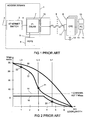
- Fig. 1 illustrates an access domain 1 with an Ethernet switch 2 with a link 3 over which data material, such as video, audio or data, is transported from a non-shown IP based service network using Ethernet or IP based transmission technology.
- POTS Packet Old Telephony Service
- PSTS Packet Old Telephony Service
- Signals on the two links 4 and 5 are multiplexed together in a non shown combiner of an IPDSLAM (IP Digital Subscriber Line Access Multiplexer) 7 and are transported to a plurality of CPEs (Customer Premises Equipments) 8 over respective DSLs (Digital Subscriber Lines) 9.
- the IPDSLAM has a plurality of connectors 10 each connected to a respective DSL.
- a CPE comprises a splitter 11 that splits the two signals on the DSL into a POTS signal and a DSL signal.
- the POTS signal goes to a telephone 12.
- the DSL signal goes to a set top box 13 to which a not shown TV or video equipment is connected.
- the DSL signal may also go to a PC 14 and a VoIP (Voice over IP) telephone 15.
- the Ethernet switch 2 has control functions for the IPDSLAM allowing users connected to the IPDSLAM to send individual requests for individual programs to a non shown content server placed in the content provider domain.
- the video or content server can be directly connected to the Ethernet switch 2.
- An IPDSLAM is provided with means that monitors the quality of the DSL.
- An IPDSLAM is also provided with a functionality called impulse noise protection (INP) that comes into action when there is impulse noise, for example electrical noise in or in the surroundings of a user's premises.
- INP impulse noise protection
- the INP functionality reduces the effects of the noise, but degrades the transmission rate.
- the length of a DSL depends of the distance between geographical location of the CPE and the IPDSLAM. This distance is commonly referred to as the loop length.
- An IPDSLAM is typically located at a CO (central office) of a network operator or in an outdoor cabinet.
- Fig. 2 Ilustrates how the transmission rate on an individual DSL varies with the loop length.
- Curve 16 is an ideal curve obtained with the standard ADSL2+ transmission mode, [Ref 1]., where no noise is on the local loop.
- Curve 17 illustrates how cross talk from other DSLs connected to the same IPDSLAM and placed in the same binder (bundle of lines) degrades the transmission rate on an individual DSL.
- Curve 18 illustrates how INP degrades the transmission rate on an individual DSL in case of impulse noise degradation.
- Vertical lines L1, L2 and L3 are three different DSLs with different loop lengths.
- L1 is a long DSL that goes to a user located about 4,5 km from the IPDSLAM 7
- L2 is a medium long DSL to another user at a distance of 3 km from the same IPDSLAM
- L3 is a short DSL to yet another user at a short distance of 1 km from the same IPDSLAM.
- the maximum point of curve 16 has been calculated for the case where the IPDSLAM is connected directly to the CPE not using any DSL. At zero distance there is a theoretical figure of a maximum transmission rate of 24 Mbps in the downstream direction (for ADSL2+). The curve is then falling with increasing distance between the IPDSLAM and the CPE and at 7 km no transmission is possible.
- An MGPEG2 coded program channel has a bit rate of about 7 Mbps. Whether a local loop can transfer a channel to a CPE depends on the quality of the local loop; the quality being measured in terms of number of mega bits (Mbps) available on the local loop. There are two main types of noise that degrades the quality; cross talk and impulse noise. As mentioned above there are many DSLs, exemplary ten, that go to a IPDSLAM. These DSLs are bundled in binders at the CO and in the surroundings of the IPDSLAM. Close to the user (user area) the bundle is then forged to the individual users (drop-lines). An individual DSL in a bundle is subjected to cross talk from traffic on the other DSLs in the bundle. Impulse noise is generated in or in the vicinity of a customer's premises.
- L1 Look at the long line L1. Ideally it has a rate of about 14 Mbps if no noise is present. If cross talk only is present on L1 the cross talk penalty is about 8 Mbps and L1 has a rate of about 6 Mbps. In the illustrated case both cross talk and impulse noise are present. The impulse noise reduces the bandwidth with about 3 Mbps. To sum up the available rate of line L1 is about 3-4 Mbps as has been marked out at point 20. Since the line is quite long, the degradation of the rate due to impulse noise protection is small, i.e. the DSL framing does not constrain the data rate. For short loops, framing limitations in DSL provoke a hard limit on the data rate as shown by horizontal part of curve 18.
- L2 can therefore take at least one channel. If L2 also suffers from impulse noise protection, which kills about 6 Mbps, its rate would be only about 5-6 Mbps and the line would not be able to transport a single channel.
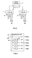
- Fig. 3 depicts the situation with the three lines L1, L2 and L3 In Fig. 2 are connected to one IPDSLAM 7 which is connected to an Ethernet switch 2 or video server over the link 4.
- Link 4 is for clarity reasons illustrated to carry only two channels CH1 and CH2 each one of 7 Mbps in bandwidth.
- the connectors are numbered from 1 to 10 in case the IPDSLAM supports 10 parallel DSLs.
- link 4 carries about 30 channels and the ten users connected to the IPDSLAM can select any of these.
- the CPE associated with L1 can not watch any channel
- the CPE at L2 can watch CH1 or CH2
- the CPE at L3 can watch CH1 and CH2.
- the POTS service is available at all of the CPEs, since it is operated in a different frequency band.
- the first relates to connectivity.
- connectivity is lacking at the CPE associated with L1, since it is not possible to connect a program to the CPE associated with line L1.
- the second relates to multichannel transmission.
- parallel transmission is not possible at the CPE associated with line L2; only one channel can be watched at the CPE associated with L2.
- the present invention aims to ease the above mentioned problems.
- An advantage achieved with the invention is that it is possible to transcode a channel to a lower rate compared to the source stream rate. This lower rate is selected so that the resulting stream fits the quality the bandwidth limited transport medium such as the DSL line. Thereby it will always be possible to connect/watch at least one channel with a reduced quality (IPTV connectivity).
- ADV2 Another advantage achieved with the invention is multichannel transmission to one and the same CPE. This is provided by transcoding a plurality of channels to different combinations of lower rates as compared to the rates of the source streams. These combinations are selected so that they fit the quality of the line they are transmitted on. One channel may be transmitted with the highest quality, while others are transmitted with reduced qualities. Other quality combinations are also possible. It is also possible to transcode and multiplex additional channels on the line.
- Fig. 4 is a block diagram of a stream adaptation device 25 in accordance with the invention. It comprises a general transcoder part 26 and a plurality of individual control units 27(1), 27(2) to 27(10), each one associated with a respective DSL line 9(1), 9(2) to 9(10) connected to the corresponding connector 10. For clarity reasons only DSL lines 9(1) and 9(2) and their respective control units 27(1) and 27(2) are shown.
- the general transcoder part comprises a plurality of transcoder units TC1, TC2 to TCn, each one receiving a respective source stream 24(1), 24(2) to 24(n).
- Source stream 24(1) carries a program channel CH1, source stream 24(2) a channel CH2, and source stream 24(n) a channel CH(n).
- Exemplary n 30 implying that there are 30 different program channels a user can select among.
- a transcoder unit TC takes its source stream and transcodes it into a plurality of transcoded streams of lower, finite and configurable rates or qualities Q1-Q5.
- the transcoded streams appear simultaneously at a corresponding number of outputs at the TC.
- each source stream is an MPEG2 coded stream with a rate of about 10 Mbps which is transcoded into 7 Mbps, 5 Mbps, 3 Mbps and 1 Mbps.
- the original source stream at 10 Mbps plus the four streams with rates 7, 5, 3 and 1 Mbps are available. It should be noted that these streams appear simultaneously in parallel at the outputs Q1-Q5.
- the stream at Q1 is the source stream with the highest quality Q1.
- the 7 Mbps transcoded stream appears and it has the next best quality Q2.
- the 5, 3 and 1 Mbps transcoded streams have the falling qualities Q3, Q4, and Q5 respectively.
- Q5 is thus the transcoded stream with the lowest ranked quality.
- the Q1-Q5 outputs are connected to respective inputs of a stream quality multiplexer 28(1) that in response to a control signal CTC1 from the control unit 27(1) associated with DSL line 9 picks out the rate by which program channel CH1 shall be transmitted on DSL line 9.
- the Q1-Q5 outputs of TC2 are connected to another stream quality multiplexer 28(2) that in response to another control signal CTC2 from the same control unit 27(1) associated with DSL line 9 picks out the rate by which program channel CH2 shall be transmitted on the same DSL line 9 to the CPE of a user, in the illustrated case DSL 9(1) to user U1.
- a plurality of different program channels at different rates are picked out at respective transcoder units TC3 to TCn, and the picked out streams are brought to inputs 29 of a channel multiplexer 30(1) which brings the picked out streams together at its output 31 and transmits them on link 4 to the IPDSLAM from where they are transmitted on DSL line 9 to user 1.
- user 1 can watch many programs with selected, different or similar, qualities Q, as determined by the respective control signals CTC1 to CTCn. These qualities Q have been selected by the control unit 27(1) and are of such rates that they in combination fit the quality of line 9; [Adv. 1], [Adv. 2]. How this is achieved will be described next.
- an IPDSLAM comprises functionality that monitors the line conditions on the DSLs connected to it.
- the line conditions comprise information on the transmission rate that is currently used on each connected DSL in both directions. This information is stored in a non-shown MIB (Management Information Base) in the IPDSLAM.
- MIB Management Information Base
- the line conditions associated to an individual DSL are used to adapt the rate of the streams that are transmitted on the individual DSL; [Adv. 1].
- Retrieving means 32 fetches the line information associated to DSL 9 from the IPDSLAM and brings it to a selector 33 that comprises receiving means 34 for receiving a user's requests for transfer of individual program channels. Communication between the IPDSLAM and the retrieving means takes place using exemplary the SNMP (Simple Network Management Protocol).
- SNMP Simple Network Management Protocol
- a controller 35 receives the line information and the user's requests and calculates the rates that are possible to use for the requested program channels with respect to the current line quality on the individual DSL line 9.
- Exemplary the line is bad and can take only 5 Mbps in which case the controller suggests transfer of one channel with Q3 quality (5 Mbps), or one channel Q4 quality + one channel with Q5 quality (4 Mbps), or for example three channels all with Q5 quality (3 Mbps).
- the controller suggests transfer of three channels with Q2 quality, or one channel with Q1 quality and two with Q2 quality, or any other combination of channels and qualities; [Adv. 2].
- the controller communicates the rates to be used to the selector and the selector generates corresponding control signals to the involved stream quality multiplexers 28(1) to 28(n).
- a control signal will set a stream quality multiplexer, so that it lets through the transcoded/non-transcoded stream with the selected transcoding rate to its output.
- the distribution of functionalites between the controller, the poller and the selector may be different than described.
- the selector functionality may be completely incorporated in the controller.
- All of the streams generated within the same transcoder unit continues to be generated and are at disposal for use by other users connected to the same or other IPDSLAM.
- Exemplary another user has a CPE 8(2) that is connected to the same IPDSLAM 7 over DSL 9(2).
- User U2 may select any of the rates at any of transcoder units TC1- TCn and have the selected streams multiplexed in the MUX 30(2) associated with CPE 8(2).
- This CPE(2) and its DSL 9(2) are associated with their own control unit 27(2).
- the individual control units 27(1) to 27(10) also comprise configuration means 37 for configuration of the transcoding rates at the transcoder units TC1 to TCn.
- a CH1 stream of Q1 quality exemplary a CH1 stream of Q1 quality
- another can take a CH2 stream of Q1 quality etcetera. This means that it is possible to reuse a lot of streams for a lot of users as is schematically illustrated at the ellipses Q1, Q2 and Q5.
- Fig. 5 also illustrates the scalability of the stream adaptation device.
- the stream adaptation device 25 is located at the IPDSLAM 7, then the transcoder part 26 can serve the exemplary ten users connected to the IPDSLAM. If the transcoder unit is expensive it would be better to have it located one level higher in a hierarchical network of a video server network. Exemplary a video server at such a higher level may serves exemplary 24 IPDSLAMS.
- the transcoder part 26 would then serve 240 DSLs with no or minor changes in its structure.
- the number of control units 27 would increase correspondingly. If the transcoder part is placed even one level higher up in the video server hierarchy then it would serve even more DSLs with no or minor changes. Since the complexity of the transcoder part does not change with the number of CPEs it serves, the stream adaptation device in accordance with the invention is easy to scale in a cost efficient manner; [Adv. 4].
- the network in which it is used can offer two program channels CH1 and CH2. All of the users in the network can then watch either CH1 or CH2 and they can watch them on either Q1, Q2, Q3, Q4 or Q5 level. Streams are always generated in the transcoder units TC1 and TC2 and it is always possible to find streams at the server in which the transcoder part is sitting; [Adv. 1].
- the channel multiplexer 30 may be a statistical MPEG multiplexer or a statistical multiplexer.
- the retrieving means 32, the selection means 33, the controller means 35 and the configuration means 37 may be implemented in software, hardware or combinations thereof.
- the transcoder units TC1 to TCn, the stream quality multiplexers, and the channel multiplexers 30(1) to 30(10) may be implemented in software, hardware or combinations thereof; [Adv. 3].
- Fig. 6 illustrates a first embodiment of the transcoder unit.
- the transcoder unit comprises a plurality of transcoders, exemplary 4, each transcoding the source stream to a respective rate, exemplary 7, 5 3 and 1 Mbps.
- Each transcoder has an input 38 and an output 39. The inputs are all connected to the transcoder's input 29 on which the source stream is received. At the outputs the respective transcoded (downcoded) streams are available together with the 10 Mbps source stream.
- Fig. 7 illustrates a second embodiment of a transcoder unit comprising a plurality of transcoders, exemplary 4, each having an input 38 and an output 39.
- the source stream exemplary CH1 at a rate of about 10 Mbps, is received at input 29 and is connected to the input of a first transcoder that transcodes the source stream into exemplary 7 Mbps.
- the source stream is also present at an output of the transcoder unit.
- the output of the first transcoder that is the 7 Mbps stream, is connected to the input of a second transcoder that transcodes the 7 Mbps stream into exemplary 5 Mbps which in turn is transcoded into a stream of 3 Mbps etcetera.
- a so called stepped transcoder results and its outputs provide five different simultaneous streams at 10, 7, 5, 3, 1 Mbps each associated with a respective quality Q'1 to Q'5 which may differ from those achieved with the Fig. 6 embodiment. It should be noted that almost all MPEG specific parameters (group of picture, mode, etc.) can be affected and changed by the transcoding units.
Landscapes
- Engineering & Computer Science (AREA)
- Multimedia (AREA)
- Signal Processing (AREA)
- Computer Networks & Wireless Communication (AREA)
- Quality & Reliability (AREA)
- Databases & Information Systems (AREA)
- Two-Way Televisions, Distribution Of Moving Picture Or The Like (AREA)
- Data Exchanges In Wide-Area Networks (AREA)
Claims (16)
- Dispositif d'adaptation de flux comprenant une pluralité d'unités de transcodage (TC1 à TCn), dans lequel chaque unité de transcodage (TC1 à TCn) comprend une pluralité de transcodeurs (TC), ayant chacun une entrée (38) et une sortie (39), où les entrées (38) de la pluralité de transcodeurs de chaque unité de transcodage (TC1 à TCn) reçoivent un flux source respectif (24(1) à 24(n)) portant un canal de programme correspondant (CH1 à CHn) et où les sorties (39) de la pluralité de transcodeurs de chaque unité de transcodage (TC1 à TCn) fournissent simultanément et de manière continu une pluralité de flux de transcodeurs de différentes vitesses de transcodage pour une utilisation par différents utilisateurs, un multiplexeur de canaux (30) avec une pluralité d'entrées (29) et une sortie (31), les sorties de chaque unité de transcodage (TC1 à TCn) étant connectées à une entrée de multiplexeur respective (29), un moyen de récupération (32) pour récupérer des informations relatives à la qualité d'un canal limité en largeur de bande (9) sur lequel le canal de programme est diffusé en continu à un équipement des locaux d'abonné CPE (8), un moyen de sélection (33) comprenant un moyen de demande d'utilisateur (34) pour recevoir une demande d'utilisateur pour un canal de programme, ledit canal de programme étant porté par un flux source, le moyen de sélection étant en communication avec un dispositif de commande (35), le dispositif de commande étant adapté pour calculer lesquelles parmi différentes vitesses de transcodage correspondent à la qualité du canal limité en largeur de bande sur la base de la demande d'utilisateur reçue, et pour communiquer les vitesses de transcodage calculées au moyen de sélection pour sélectionner les flux de transcodeur correspondant aux vitesses de transcodage calculées, et la sortie du multiplexeur (31) étant adaptée pour une connexion avec le canal limité en largeur de bande (9) de manière à permettre un transfert simultané d'au moins deux canaux de programme sur le même canal limité en largeur de bande (9), ledit multiplexeur de canaux supportant le CPE des différents utilisateurs.
- Dispositif d'adaptation de flux selon la revendication 1, dans lequel le moyen de sélection (33) est adapté pour recevoir à partir d'un seul et même utilisateur une demande pour transférer deux ou plus de deux canaux de programme simultanés.
- Dispositif d'adaptation de flux selon la revendication 2, dans lequel le dispositif de commande (35) en réponse à une demande de transfert de deux ou plus de deux canaux de programme simultanés (CH1 à CHn) est adapté pour calculer lesquelles parmi ladite pluralité de vitesses de transcodage sont possibles à utiliser pour la transmission simultanée des canaux de programme demandés sur le canal limité en largeur de bande (9).
- Dispositif d'adaptation de flux selon la revendication 3, dans lequel le dispositif de commande (35) est adapté pour interagir avec l'utilisateur (U1) et pour proposer des vitesses de transcodage qui sont possibles à utiliser pour les différents canaux de programme qui doivent être transférés simultanément sur le canal limité en largeur de bande.
- Dispositif d'adaptation de flux selon la revendication 4, dans lequel chaque unité de transcodage (TC1 à TCn) comprend un transcodeur étagé ; un transcodeur étagé à son tour comprenant une pluralité de transcodeurs (TC) ayant chacun une entrée (38) et une sortie (39), l'entrée d'un transcodeur à un étage étant connectée à la sortie d'un transcodeur à un étage supérieur, et la sortie du transcodeur audit étage étant connectée à l'entrée d'un étage immédiatement inférieur, le transcodeur à l'étage le plus élevé recevant un flux source (24(1) à 24(n)), et les sorties de chaque transcodeur fournissant les différentes vitesses de transcodage.
- Dispositif d'adaptation de flux selon l'une des revendications 1 à 5, comprenant un moyen (37) pour la configuration des vitesses de transcodage.
- Dispositif d'adaptation de flux selon la revendication 6, dans lequel le canal limité en largeur de bande est une ligne d'abonné numérique, DSL.
- Dispositif d'adaptation de flux selon la revendication 7, dans lequel un multiplexeur de ligne d'abonné numérique IP, IPDSLAM, (7) est connecté à la DSL ; et un seul multiplexeur de canaux (3) par IPDSLAM est prévu.
- Dispositif d'adaptation de flux selon la revendication 7, utilisant le protocole simple de gestion de réseau, SNMP, pour une communication entre le moyen de sélection (33) et l'IPDSLAM (7).
- Dispositif d'adaptation de flux selon la revendication 1, dans lequel ledit moyen de récupération (32) est adapté pour interroger une base d'informations de gestion, MIB, comprenant des informations sur la qualité du canal limité en largeur de bande (9) et pour recevoir des informations de la qualité de ligne.
- Dispositif d'adaptation de flux selon la revendication 1, le dispositif d'adaptation de flux étant situé au niveau d'un serveur de contenu, d'un serveur vidéo, ou au niveau d'un commutateur Ethernet (2).
- Dispositif d'adaptation de flux selon l'une des revendications 1 à 11, dans lequel le canal limité en largeur de bande (9) est une connexion radio entre un téléphone cellulaire et une station de base.
- Dispositif d'adaptation de flux selon la revendication 1, dans lequel le canal limité en largeur de bande est une fibre optique.
- Dispositif d'adaptation de flux selon la revendication 1, utilisant le taux d'erreur binaire en tant que mesure de la qualité de la connexion radio.
- Noeud de réseau permettant d'adapter la vitesse avec laquelle un ou plusieurs flux sources (24(1) à 24(n)) sont transmis sur un canal limité en largeur de bande (9), le noeud comprenant un dispositif selon la revendication 1.
- Noeud de réseau selon la revendication 15, le noeud étant un serveur de contenu, un serveur vidéo ou un commutateur Ethernet (2).
Applications Claiming Priority (1)
| Application Number | Priority Date | Filing Date | Title |
|---|---|---|---|
| PCT/SE2006/050272 WO2008013484A1 (fr) | 2006-07-25 | 2006-07-25 | Procédé et dispositif d'adaptation de flux |
Publications (3)
| Publication Number | Publication Date |
|---|---|
| EP2044713A1 EP2044713A1 (fr) | 2009-04-08 |
| EP2044713A4 EP2044713A4 (fr) | 2012-01-04 |
| EP2044713B1 true EP2044713B1 (fr) | 2015-01-14 |
Family
ID=38981724
Family Applications (1)
| Application Number | Title | Priority Date | Filing Date |
|---|---|---|---|
| EP06769652.6A Not-in-force EP2044713B1 (fr) | 2006-07-25 | 2006-07-25 | Procédé et dispositif d'adaptation de flux |
Country Status (3)
| Country | Link |
|---|---|
| US (1) | US20100017836A1 (fr) |
| EP (1) | EP2044713B1 (fr) |
| WO (1) | WO2008013484A1 (fr) |
Families Citing this family (8)
| Publication number | Priority date | Publication date | Assignee | Title |
|---|---|---|---|---|
| US9516375B2 (en) * | 2008-12-02 | 2016-12-06 | Orckit Ip, Llc | Edge optimized transrating system |
| US9538220B2 (en) | 2009-06-12 | 2017-01-03 | Wi-Lan Labs, Inc. | Video streaming quality of experience degradation control using a video quality metric |
| US20130298170A1 (en) * | 2009-06-12 | 2013-11-07 | Cygnus Broadband, Inc. | Video streaming quality of experience recovery using a video quality metric |
| EP2573997A1 (fr) | 2011-09-26 | 2013-03-27 | Thomson Licensing | Procédé de contrôle de la bande passante et dispositif correspondant |
| CN103957428A (zh) * | 2014-05-16 | 2014-07-30 | 中国科学院上海高等研究院 | 基于众核处理器且带多码率转码功能的流媒体服务器 |
| CN105791975A (zh) * | 2014-12-26 | 2016-07-20 | 上海百事通信息技术股份有限公司 | 多屏互动流媒体平台及系统 |
| CN104935955B (zh) * | 2015-05-29 | 2019-01-25 | 腾讯科技(北京)有限公司 | 一种传输直播视频流的方法、装置和系统 |
| CN105610823B (zh) * | 2015-12-28 | 2018-09-11 | 武汉鸿瑞达信息技术有限公司 | 一种基于任务向量的流媒体处理方法及其处理系统架构 |
Family Cites Families (9)
| Publication number | Priority date | Publication date | Assignee | Title |
|---|---|---|---|---|
| US7089309B2 (en) * | 2001-03-21 | 2006-08-08 | Theplatform For Media, Inc. | Method and system for managing and distributing digital media |
| CN1504029A (zh) * | 2001-04-20 | 2004-06-09 | ���dz� | 多路传输复用器的图形用户界面 |
| US20020176361A1 (en) * | 2001-05-25 | 2002-11-28 | Yunnan Wu | End-to-end traffic management and adaptive multi-hop multimedia transmission |
| US9612965B2 (en) * | 2003-06-24 | 2017-04-04 | Hewlett-Packard Development Company, L.P. | Method and system for servicing streaming media |
| US7274740B2 (en) * | 2003-06-25 | 2007-09-25 | Sharp Laboratories Of America, Inc. | Wireless video transmission system |
| EP1580914A1 (fr) * | 2004-03-26 | 2005-09-28 | STMicroelectronics S.r.l. | Méthode et système pour contrôler l'opération d'un réseau |
| US20060150055A1 (en) * | 2005-01-06 | 2006-07-06 | Terayon Communication Systems, Inc. | Adaptive information delivery system using FEC feedback |
| US7979885B2 (en) * | 2005-08-11 | 2011-07-12 | Harmonic Inc. | Real time bit rate switching for internet protocol television |
| US7693081B1 (en) * | 2006-06-28 | 2010-04-06 | Alcatel Lucent | Integrated IP DSLAM test monitor |
-
2006
- 2006-07-25 EP EP06769652.6A patent/EP2044713B1/fr not_active Not-in-force
- 2006-07-25 WO PCT/SE2006/050272 patent/WO2008013484A1/fr not_active Ceased
- 2006-07-25 US US12/374,608 patent/US20100017836A1/en not_active Abandoned
Also Published As
| Publication number | Publication date |
|---|---|
| EP2044713A4 (fr) | 2012-01-04 |
| US20100017836A1 (en) | 2010-01-21 |
| EP2044713A1 (fr) | 2009-04-08 |
| WO2008013484A1 (fr) | 2008-01-31 |
Similar Documents
| Publication | Publication Date | Title |
|---|---|---|
| JP4115938B2 (ja) | マルチプロトコル・ビデオおよびデータ・サービスのためのアクセス・ノード | |
| US10327039B2 (en) | Methods, systems and apparatus for providing video transmissions over multiple media | |
| EP0801858B1 (fr) | Central téléphonique multimedia et procédé de provision d'une pluralité de services de télécommunication multimedia | |
| US7075919B1 (en) | System and method for providing integrated voice, video and data to customer premises over a single network | |
| US7239698B2 (en) | DOCSIS network interface device and methods and systems for using the same | |
| US20030093799A1 (en) | Streamed content Delivery | |
| US20110247043A1 (en) | Real Time Bit Rate Switching for Internet Protocol Television | |
| US20110228708A1 (en) | Ethernet transport over a telephone line | |
| MXPA00012913A (es) | Modelo de referencia de arquitectura de red itn ip con arquitectura de red telefonica por cable de banda amplia. | |
| US20040071216A1 (en) | Delivering video over an ATM/DSL network using a multi-layered video coding system | |
| CA2792002A1 (fr) | Systeme et procede de calcul informatise en micronuage | |
| EP2044713B1 (fr) | Procédé et dispositif d'adaptation de flux | |
| CA2260072A1 (fr) | Procede et configuration pour radiotelecommunications integrees via un reseau de television par cable (catv) | |
| KR20040106529A (ko) | 디지털 가입자 라인 네트워크를 위한 비디오 수신기 구조 | |
| US8102866B2 (en) | Centralized system for the remote monitoring of multimedia signals | |
| US7768938B2 (en) | Systems and methods for providing multiple communication services over existing twisted pair access lines | |
| US6178179B1 (en) | System and method for linking a VDSL based distribution system with an xDSL based system | |
| US20020002709A1 (en) | Method and system for transmitting multimedia data with downstream data transfer over local TV broadcasting channel and for receiving request with upstream data transfer over another channel | |
| Chrissan | Uni-DSLT: One DSL for universal service | |
| US20080130247A1 (en) | Broadband-narrowband combining board in integrated access apparatus | |
| US20070036177A1 (en) | Method and apparatus for managing delivery of video over a digital subscriber line | |
| KR100526561B1 (ko) | 이더넷 프로토콜을 이용한 디지털 방송 서비스 시스템 및그의 디지털 방송 데이터 전송 방법 | |
| El-Sayed et al. | Access transport network for IPTV video distribution | |
| Dyke et al. | A review of the technical options for evolving FITL to support small business and residential services | |
| Limaye et al. | Impact of bandwidth demand growth on hfc networks |
Legal Events
| Date | Code | Title | Description |
|---|---|---|---|
| PUAI | Public reference made under article 153(3) epc to a published international application that has entered the european phase |
Free format text: ORIGINAL CODE: 0009012 |
|
| 17P | Request for examination filed |
Effective date: 20090107 |
|
| AK | Designated contracting states |
Kind code of ref document: A1 Designated state(s): AT BE BG CH CY CZ DE DK EE ES FI FR GB GR HU IE IS IT LI LT LU LV MC NL PL PT RO SE SI SK TR |
|
| AX | Request for extension of the european patent |
Extension state: AL BA HR MK RS |
|
| A4 | Supplementary search report drawn up and despatched |
Effective date: 20111206 |
|
| 17Q | First examination report despatched |
Effective date: 20120109 |
|
| DAX | Request for extension of the european patent (deleted) | ||
| GRAP | Despatch of communication of intention to grant a patent |
Free format text: ORIGINAL CODE: EPIDOSNIGR1 |
|
| RIC1 | Information provided on ipc code assigned before grant |
Ipc: H04N 21/435 20110101ALI20140903BHEP Ipc: H04N 7/24 20110101ALI20140903BHEP Ipc: H04N 21/235 20110101ALI20140903BHEP Ipc: H04L 29/06 20060101ALI20140903BHEP Ipc: H04N 21/2662 20110101ALI20140903BHEP Ipc: H04L 1/00 20060101AFI20140903BHEP Ipc: H04N 19/40 20140101ALI20140903BHEP Ipc: H04N 21/643 20110101ALI20140903BHEP Ipc: H04N 21/2343 20110101ALI20140903BHEP |
|
| INTG | Intention to grant announced |
Effective date: 20140926 |
|
| GRAS | Grant fee paid |
Free format text: ORIGINAL CODE: EPIDOSNIGR3 |
|
| GRAA | (expected) grant |
Free format text: ORIGINAL CODE: 0009210 |
|
| AK | Designated contracting states |
Kind code of ref document: B1 Designated state(s): AT BE BG CH CY CZ DE DK EE ES FI FR GB GR HU IE IS IT LI LT LU LV MC NL PL PT RO SE SI SK TR |
|
| REG | Reference to a national code |
Ref country code: GB Ref legal event code: FG4D |
|
| REG | Reference to a national code |
Ref country code: CH Ref legal event code: EP |
|
| REG | Reference to a national code |
Ref country code: IE Ref legal event code: FG4D |
|
| REG | Reference to a national code |
Ref country code: AT Ref legal event code: REF Ref document number: 707506 Country of ref document: AT Kind code of ref document: T Effective date: 20150215 |
|
| REG | Reference to a national code |
Ref country code: DE Ref legal event code: R096 Ref document number: 602006044325 Country of ref document: DE Effective date: 20150305 |
|
| REG | Reference to a national code |
Ref country code: NL Ref legal event code: VDEP Effective date: 20150114 |
|
| REG | Reference to a national code |
Ref country code: AT Ref legal event code: MK05 Ref document number: 707506 Country of ref document: AT Kind code of ref document: T Effective date: 20150114 |
|
| REG | Reference to a national code |
Ref country code: LT Ref legal event code: MG4D |
|
| PG25 | Lapsed in a contracting state [announced via postgrant information from national office to epo] |
Ref country code: LT Free format text: LAPSE BECAUSE OF FAILURE TO SUBMIT A TRANSLATION OF THE DESCRIPTION OR TO PAY THE FEE WITHIN THE PRESCRIBED TIME-LIMIT Effective date: 20150114 Ref country code: BG Free format text: LAPSE BECAUSE OF FAILURE TO SUBMIT A TRANSLATION OF THE DESCRIPTION OR TO PAY THE FEE WITHIN THE PRESCRIBED TIME-LIMIT Effective date: 20150414 Ref country code: FI Free format text: LAPSE BECAUSE OF FAILURE TO SUBMIT A TRANSLATION OF THE DESCRIPTION OR TO PAY THE FEE WITHIN THE PRESCRIBED TIME-LIMIT Effective date: 20150114 Ref country code: ES Free format text: LAPSE BECAUSE OF FAILURE TO SUBMIT A TRANSLATION OF THE DESCRIPTION OR TO PAY THE FEE WITHIN THE PRESCRIBED TIME-LIMIT Effective date: 20150114 Ref country code: SE Free format text: LAPSE BECAUSE OF FAILURE TO SUBMIT A TRANSLATION OF THE DESCRIPTION OR TO PAY THE FEE WITHIN THE PRESCRIBED TIME-LIMIT Effective date: 20150114 |
|
| PG25 | Lapsed in a contracting state [announced via postgrant information from national office to epo] |
Ref country code: PL Free format text: LAPSE BECAUSE OF FAILURE TO SUBMIT A TRANSLATION OF THE DESCRIPTION OR TO PAY THE FEE WITHIN THE PRESCRIBED TIME-LIMIT Effective date: 20150114 Ref country code: AT Free format text: LAPSE BECAUSE OF FAILURE TO SUBMIT A TRANSLATION OF THE DESCRIPTION OR TO PAY THE FEE WITHIN THE PRESCRIBED TIME-LIMIT Effective date: 20150114 Ref country code: IS Free format text: LAPSE BECAUSE OF FAILURE TO SUBMIT A TRANSLATION OF THE DESCRIPTION OR TO PAY THE FEE WITHIN THE PRESCRIBED TIME-LIMIT Effective date: 20150514 Ref country code: LV Free format text: LAPSE BECAUSE OF FAILURE TO SUBMIT A TRANSLATION OF THE DESCRIPTION OR TO PAY THE FEE WITHIN THE PRESCRIBED TIME-LIMIT Effective date: 20150114 Ref country code: NL Free format text: LAPSE BECAUSE OF FAILURE TO SUBMIT A TRANSLATION OF THE DESCRIPTION OR TO PAY THE FEE WITHIN THE PRESCRIBED TIME-LIMIT Effective date: 20150114 Ref country code: GR Free format text: LAPSE BECAUSE OF FAILURE TO SUBMIT A TRANSLATION OF THE DESCRIPTION OR TO PAY THE FEE WITHIN THE PRESCRIBED TIME-LIMIT Effective date: 20150415 |
|
| REG | Reference to a national code |
Ref country code: DE Ref legal event code: R097 Ref document number: 602006044325 Country of ref document: DE |
|
| PG25 | Lapsed in a contracting state [announced via postgrant information from national office to epo] |
Ref country code: SK Free format text: LAPSE BECAUSE OF FAILURE TO SUBMIT A TRANSLATION OF THE DESCRIPTION OR TO PAY THE FEE WITHIN THE PRESCRIBED TIME-LIMIT Effective date: 20150114 Ref country code: RO Free format text: LAPSE BECAUSE OF FAILURE TO SUBMIT A TRANSLATION OF THE DESCRIPTION OR TO PAY THE FEE WITHIN THE PRESCRIBED TIME-LIMIT Effective date: 20150114 Ref country code: CZ Free format text: LAPSE BECAUSE OF FAILURE TO SUBMIT A TRANSLATION OF THE DESCRIPTION OR TO PAY THE FEE WITHIN THE PRESCRIBED TIME-LIMIT Effective date: 20150114 Ref country code: EE Free format text: LAPSE BECAUSE OF FAILURE TO SUBMIT A TRANSLATION OF THE DESCRIPTION OR TO PAY THE FEE WITHIN THE PRESCRIBED TIME-LIMIT Effective date: 20150114 Ref country code: DK Free format text: LAPSE BECAUSE OF FAILURE TO SUBMIT A TRANSLATION OF THE DESCRIPTION OR TO PAY THE FEE WITHIN THE PRESCRIBED TIME-LIMIT Effective date: 20150114 |
|
| PLBE | No opposition filed within time limit |
Free format text: ORIGINAL CODE: 0009261 |
|
| STAA | Information on the status of an ep patent application or granted ep patent |
Free format text: STATUS: NO OPPOSITION FILED WITHIN TIME LIMIT |
|
| 26N | No opposition filed |
Effective date: 20151015 |
|
| PG25 | Lapsed in a contracting state [announced via postgrant information from national office to epo] |
Ref country code: IT Free format text: LAPSE BECAUSE OF FAILURE TO SUBMIT A TRANSLATION OF THE DESCRIPTION OR TO PAY THE FEE WITHIN THE PRESCRIBED TIME-LIMIT Effective date: 20150114 |
|
| PG25 | Lapsed in a contracting state [announced via postgrant information from national office to epo] |
Ref country code: SI Free format text: LAPSE BECAUSE OF FAILURE TO SUBMIT A TRANSLATION OF THE DESCRIPTION OR TO PAY THE FEE WITHIN THE PRESCRIBED TIME-LIMIT Effective date: 20150114 Ref country code: MC Free format text: LAPSE BECAUSE OF FAILURE TO SUBMIT A TRANSLATION OF THE DESCRIPTION OR TO PAY THE FEE WITHIN THE PRESCRIBED TIME-LIMIT Effective date: 20150114 |
|
| REG | Reference to a national code |
Ref country code: CH Ref legal event code: PL |
|
| PG25 | Lapsed in a contracting state [announced via postgrant information from national office to epo] |
Ref country code: LU Free format text: LAPSE BECAUSE OF FAILURE TO SUBMIT A TRANSLATION OF THE DESCRIPTION OR TO PAY THE FEE WITHIN THE PRESCRIBED TIME-LIMIT Effective date: 20150725 |
|
| REG | Reference to a national code |
Ref country code: IE Ref legal event code: MM4A |
|
| PG25 | Lapsed in a contracting state [announced via postgrant information from national office to epo] |
Ref country code: LI Free format text: LAPSE BECAUSE OF NON-PAYMENT OF DUE FEES Effective date: 20150731 Ref country code: CH Free format text: LAPSE BECAUSE OF NON-PAYMENT OF DUE FEES Effective date: 20150731 |
|
| PG25 | Lapsed in a contracting state [announced via postgrant information from national office to epo] |
Ref country code: BE Free format text: LAPSE BECAUSE OF FAILURE TO SUBMIT A TRANSLATION OF THE DESCRIPTION OR TO PAY THE FEE WITHIN THE PRESCRIBED TIME-LIMIT Effective date: 20150114 |
|
| REG | Reference to a national code |
Ref country code: FR Ref legal event code: PLFP Year of fee payment: 11 |
|
| PG25 | Lapsed in a contracting state [announced via postgrant information from national office to epo] |
Ref country code: IE Free format text: LAPSE BECAUSE OF NON-PAYMENT OF DUE FEES Effective date: 20150725 |
|
| PG25 | Lapsed in a contracting state [announced via postgrant information from national office to epo] |
Ref country code: HU Free format text: LAPSE BECAUSE OF FAILURE TO SUBMIT A TRANSLATION OF THE DESCRIPTION OR TO PAY THE FEE WITHIN THE PRESCRIBED TIME-LIMIT; INVALID AB INITIO Effective date: 20060725 |
|
| PG25 | Lapsed in a contracting state [announced via postgrant information from national office to epo] |
Ref country code: CY Free format text: LAPSE BECAUSE OF FAILURE TO SUBMIT A TRANSLATION OF THE DESCRIPTION OR TO PAY THE FEE WITHIN THE PRESCRIBED TIME-LIMIT Effective date: 20150114 |
|
| REG | Reference to a national code |
Ref country code: FR Ref legal event code: PLFP Year of fee payment: 12 |
|
| PG25 | Lapsed in a contracting state [announced via postgrant information from national office to epo] |
Ref country code: TR Free format text: LAPSE BECAUSE OF FAILURE TO SUBMIT A TRANSLATION OF THE DESCRIPTION OR TO PAY THE FEE WITHIN THE PRESCRIBED TIME-LIMIT Effective date: 20150114 |
|
| PG25 | Lapsed in a contracting state [announced via postgrant information from national office to epo] |
Ref country code: PT Free format text: LAPSE BECAUSE OF FAILURE TO SUBMIT A TRANSLATION OF THE DESCRIPTION OR TO PAY THE FEE WITHIN THE PRESCRIBED TIME-LIMIT Effective date: 20150114 |
|
| REG | Reference to a national code |
Ref country code: FR Ref legal event code: PLFP Year of fee payment: 13 |
|
| PGFP | Annual fee paid to national office [announced via postgrant information from national office to epo] |
Ref country code: FR Payment date: 20180726 Year of fee payment: 13 Ref country code: DE Payment date: 20180727 Year of fee payment: 13 |
|
| PGFP | Annual fee paid to national office [announced via postgrant information from national office to epo] |
Ref country code: GB Payment date: 20180727 Year of fee payment: 13 |
|
| REG | Reference to a national code |
Ref country code: DE Ref legal event code: R119 Ref document number: 602006044325 Country of ref document: DE |
|
| GBPC | Gb: european patent ceased through non-payment of renewal fee |
Effective date: 20190725 |
|
| PG25 | Lapsed in a contracting state [announced via postgrant information from national office to epo] |
Ref country code: GB Free format text: LAPSE BECAUSE OF NON-PAYMENT OF DUE FEES Effective date: 20190725 Ref country code: DE Free format text: LAPSE BECAUSE OF NON-PAYMENT OF DUE FEES Effective date: 20200201 |
|
| PG25 | Lapsed in a contracting state [announced via postgrant information from national office to epo] |
Ref country code: FR Free format text: LAPSE BECAUSE OF NON-PAYMENT OF DUE FEES Effective date: 20190731 |