EP2045016B1 - Zerkleinerungsvorrichtung - Google Patents
Zerkleinerungsvorrichtung Download PDFInfo
- Publication number
- EP2045016B1 EP2045016B1 EP07790985.1A EP07790985A EP2045016B1 EP 2045016 B1 EP2045016 B1 EP 2045016B1 EP 07790985 A EP07790985 A EP 07790985A EP 2045016 B1 EP2045016 B1 EP 2045016B1
- Authority
- EP
- European Patent Office
- Prior art keywords
- crushed
- opening
- hammer
- plate
- casing
- Prior art date
- Legal status (The legal status is an assumption and is not a legal conclusion. Google has not performed a legal analysis and makes no representation as to the accuracy of the status listed.)
- Active
Links
Images





Classifications
-
- B—PERFORMING OPERATIONS; TRANSPORTING
- B02—CRUSHING, PULVERISING, OR DISINTEGRATING; PREPARATORY TREATMENT OF GRAIN FOR MILLING
- B02C—CRUSHING, PULVERISING, OR DISINTEGRATING IN GENERAL; MILLING GRAIN
- B02C13/00—Disintegrating by mills having rotary beater elements ; Hammer mills
- B02C13/02—Disintegrating by mills having rotary beater elements ; Hammer mills with horizontal rotor shaft
- B02C13/06—Disintegrating by mills having rotary beater elements ; Hammer mills with horizontal rotor shaft with beaters rigidly connected to the rotor
-
- B—PERFORMING OPERATIONS; TRANSPORTING
- B02—CRUSHING, PULVERISING, OR DISINTEGRATING; PREPARATORY TREATMENT OF GRAIN FOR MILLING
- B02C—CRUSHING, PULVERISING, OR DISINTEGRATING IN GENERAL; MILLING GRAIN
- B02C13/00—Disintegrating by mills having rotary beater elements ; Hammer mills
- B02C13/26—Details
- B02C13/28—Shape or construction of beater elements
-
- B—PERFORMING OPERATIONS; TRANSPORTING
- B02—CRUSHING, PULVERISING, OR DISINTEGRATING; PREPARATORY TREATMENT OF GRAIN FOR MILLING
- B02C—CRUSHING, PULVERISING, OR DISINTEGRATING IN GENERAL; MILLING GRAIN
- B02C13/00—Disintegrating by mills having rotary beater elements ; Hammer mills
- B02C13/26—Details
- B02C13/28—Shape or construction of beater elements
- B02C13/2804—Shape or construction of beater elements the beater elements being rigidly connected to the rotor
-
- B—PERFORMING OPERATIONS; TRANSPORTING
- B02—CRUSHING, PULVERISING, OR DISINTEGRATING; PREPARATORY TREATMENT OF GRAIN FOR MILLING
- B02C—CRUSHING, PULVERISING, OR DISINTEGRATING IN GENERAL; MILLING GRAIN
- B02C13/00—Disintegrating by mills having rotary beater elements ; Hammer mills
- B02C13/26—Details
- B02C13/282—Shape or inner surface of mill-housings
- B02C13/284—Built-in screens
-
- B—PERFORMING OPERATIONS; TRANSPORTING
- B02—CRUSHING, PULVERISING, OR DISINTEGRATING; PREPARATORY TREATMENT OF GRAIN FOR MILLING
- B02C—CRUSHING, PULVERISING, OR DISINTEGRATING IN GENERAL; MILLING GRAIN
- B02C13/00—Disintegrating by mills having rotary beater elements ; Hammer mills
- B02C13/26—Details
- B02C13/286—Feeding or discharge
-
- B—PERFORMING OPERATIONS; TRANSPORTING
- B02—CRUSHING, PULVERISING, OR DISINTEGRATING; PREPARATORY TREATMENT OF GRAIN FOR MILLING
- B02C—CRUSHING, PULVERISING, OR DISINTEGRATING IN GENERAL; MILLING GRAIN
- B02C18/00—Disintegrating by knives or other cutting or tearing members which chop material into fragments
- B02C18/06—Disintegrating by knives or other cutting or tearing members which chop material into fragments with rotating knives
- B02C18/14—Disintegrating by knives or other cutting or tearing members which chop material into fragments with rotating knives within horizontal containers
-
- B—PERFORMING OPERATIONS; TRANSPORTING
- B02—CRUSHING, PULVERISING, OR DISINTEGRATING; PREPARATORY TREATMENT OF GRAIN FOR MILLING
- B02C—CRUSHING, PULVERISING, OR DISINTEGRATING IN GENERAL; MILLING GRAIN
- B02C18/00—Disintegrating by knives or other cutting or tearing members which chop material into fragments
- B02C18/06—Disintegrating by knives or other cutting or tearing members which chop material into fragments with rotating knives
- B02C18/16—Details
- B02C18/18—Knives; Mountings thereof
-
- B—PERFORMING OPERATIONS; TRANSPORTING
- B02—CRUSHING, PULVERISING, OR DISINTEGRATING; PREPARATORY TREATMENT OF GRAIN FOR MILLING
- B02C—CRUSHING, PULVERISING, OR DISINTEGRATING IN GENERAL; MILLING GRAIN
- B02C18/00—Disintegrating by knives or other cutting or tearing members which chop material into fragments
- B02C18/06—Disintegrating by knives or other cutting or tearing members which chop material into fragments with rotating knives
- B02C18/16—Details
- B02C18/22—Feed or discharge means
-
- B—PERFORMING OPERATIONS; TRANSPORTING
- B02—CRUSHING, PULVERISING, OR DISINTEGRATING; PREPARATORY TREATMENT OF GRAIN FOR MILLING
- B02C—CRUSHING, PULVERISING, OR DISINTEGRATING IN GENERAL; MILLING GRAIN
- B02C13/00—Disintegrating by mills having rotary beater elements ; Hammer mills
- B02C13/26—Details
- B02C13/286—Feeding or discharge
- B02C2013/2869—Arrangements of feed and discharge means in relation to each other
-
- B—PERFORMING OPERATIONS; TRANSPORTING
- B02—CRUSHING, PULVERISING, OR DISINTEGRATING; PREPARATORY TREATMENT OF GRAIN FOR MILLING
- B02C—CRUSHING, PULVERISING, OR DISINTEGRATING IN GENERAL; MILLING GRAIN
- B02C18/00—Disintegrating by knives or other cutting or tearing members which chop material into fragments
- B02C18/0007—Disintegrating by knives or other cutting or tearing members which chop material into fragments specially adapted for disintegrating documents
- B02C2018/0015—Disintegrating by knives or other cutting or tearing members which chop material into fragments specially adapted for disintegrating documents for disintegrating CDs, DVDs and/or credit cards
-
- B—PERFORMING OPERATIONS; TRANSPORTING
- B02—CRUSHING, PULVERISING, OR DISINTEGRATING; PREPARATORY TREATMENT OF GRAIN FOR MILLING
- B02C—CRUSHING, PULVERISING, OR DISINTEGRATING IN GENERAL; MILLING GRAIN
- B02C18/00—Disintegrating by knives or other cutting or tearing members which chop material into fragments
- B02C18/06—Disintegrating by knives or other cutting or tearing members which chop material into fragments with rotating knives
- B02C18/16—Details
- B02C2018/162—Shape or inner surface of shredder-housings
-
- B—PERFORMING OPERATIONS; TRANSPORTING
- B02—CRUSHING, PULVERISING, OR DISINTEGRATING; PREPARATORY TREATMENT OF GRAIN FOR MILLING
- B02C—CRUSHING, PULVERISING, OR DISINTEGRATING IN GENERAL; MILLING GRAIN
- B02C18/00—Disintegrating by knives or other cutting or tearing members which chop material into fragments
- B02C18/06—Disintegrating by knives or other cutting or tearing members which chop material into fragments with rotating knives
- B02C18/16—Details
- B02C18/18—Knives; Mountings thereof
- B02C2018/188—Stationary counter-knives; Mountings thereof
Definitions
- the present invention relates a crusher.
- the present invention relates to a crusher that can crush various products, such as magnetic tape recording media including cassette tapes and the like, optical recording media, and substrates.
- a crusher which includes a casing and a crushing means (Patent Document 1 and Patent Document 2).
- the casing includes an upper loading opening into which an object to be crushed is loaded, and a lower discharge opening from which a crushed object is discharged.
- the crushing means is disposed in a crushing chamber within the casing.
- a discharge plate 5 is placed in a lower discharge opening 3 of a casing 1.
- the discharge plate 5 has a plurality of discharge holes 4.
- a crushing chamber 6 is formed by inner surfaces of the plate 5 and the casing 1.
- a crushing means 7 is disposed in the crushing chamber 6.
- the crushing means 7 includes hammer members 9, fixed blades 10, and the like.
- the hammer members 9 are arranged on a circular rotating plate 8 at a predetermined pitch along a circumferential direction.
- the fixed blades 10 are fixed onto the inner surface of the crushing chamber 6 (inner surface of the casing 1).
- the fixed blades 10 are arranged along a circular arc surface corresponding to a circular trajectory followed by the front end edge of the hammer members 9 during rotation. corresponding to a circular trajectory followed by the front end edge of the hammer members 9 during rotation.
- FR 1 277 341 A discloses a hammermill consisting essentially of a removable fixing in a casing opening of the frame or housing of the mill and supporting and shielding plates of various shock model.
- JP 08 084937 A discloses a crusher that can stably crush various information media.
- Hammer members that extend from a rotation shaft in a radial direction and rotate with a rotation of the rotation shaft are housed in a casing that includes an upper loading opening for loading an object to be crushed and a lower discharge opening for discharging a crushed object.
- Fixed blades are arranged within the casing on an outer diameter side of the hammer members. The hammer members and the fixed blades crush the object to be crushed when the hammer members are rotated.
- hammer members that extend from a rotation shaft in a radial direction and rotate with a rotation of the rotation shaft are housed in a casing.
- the casing includes an upper loading opening for loading an object to be crushed and a lower discharge opening for discharging a crushed object.
- Fixed blades are arranged within the casing on an outer diameter side of the hammer members. The hammer members and the fixed blades crush the object to be crushed when the hammer members rotate.
- An opening that can be opened and closed by opening and closing operations of a lid member is formed on the casing.
- Plate fitting grooves are also formed on the casing, along a circular arc surface corresponding to a circular trajectory followed by a front end edge of the hammer members during rotation.
- the fixed blades are attached to a curved holding plate. The curved holding plate is fitted into the plate fitting grooves from the opening.
- the fixed blades are attached to the curved holding plate, handleability of the fixed blades is excellent.
- the curved holding plate can be fitted into the plate fitting grooves.
- the fixed blades can be easily mounted on the casing.
- the plate can be fitted through the opening provided in the casing. When the opening is in a closed state by the lid member, the plate fitted into the plate fitting grooves can be fixed.
- hammer members that extend from a rotation shaft in a radial direction and rotate with a rotation of the rotation shaft are housed in a casing.
- the casing includes an upper loading opening for loading an object to be crushed and a lower discharge opening for discharging a crushed object.
- Fixed blades are arranged within the casing on an outer diameter side of the hammer members. The hammer members and the fixed blades crush the object to be crushed when the hammer members rotate.
- a guide path that guides the object to be crushed that is loaded from the upper loading opening into a crushing chamber in which the object to be crushed is crushed by the hammer members and the fixed blades is provided within the casing.
- Guide bodies that lift the object to be crushed towards the crushing chamber side are provided on a downstream side of the guide path.
- the object to be crushed when the object to be crushed is loaded from the upper loading opening, the object to be crushed is guided by the guide path and fed to the crushing chamber. At this time, the guide bodies provided on the downstream side of the guide path can lift the object to be crushed towards the crushing chamber side. As a result, the object to be crushed can come into contact with the hammer members.
- an opening that can be opened and closed by opening and closing operations of a lid member can be formed on the casing.
- Plate fitting grooves can also be formed on the casing, along a circular arc surface corresponding to a circular trajectory followed by a front end edge of the hammer members during rotation.
- the guide bodies can be can be fitted into the plate fitting grooves from the opening.
- the guide bodies can be easily mounted on the casing.
- the plate can be fitted through the opening provided in the casing.
- a curved discharge plate including numerous holes for discharging the crushed object can be placed in the lower discharge opening of the casing. As a result, the crushed object can be discharged outside (below) from the holes in the circular discharge plate.
- a plurality of crushing assisting projections can be provided on an inner surface of the lid member.
- An optimal loading direction into the crushing chamber differs depending on the type of object to be crushed.
- the hammer members rotate around an axial center of the rotation shaft, depending on an angle formed in relation to a tangent of a circular trajectory followed by the front end edge of the hammer members during rotation, the object to be crushed is thrown from the crushing chamber by the rotation of the hammer members.
- the angle, namely the loading direction differs depending on the type of object to be crushed. Therefore, a shifting means is preferably provided to switch the loading direction into the crushing chamber depending on the type of object to be crushed that is loaded into the upper loading opening.
- the hammer member includes at least a first hammer member a first hammer member having a crushing blade on a front end side, and a second hammer member having a planar hammer section on a front end side and a crushing blade in the center.
- the first hammer member and the second hammer member can be selectively attached based on the type of object to be crushed.
- the crushing blade is provided on the front end side, a sheet-shaped object can be cut by the crushing blade of the hammer member.
- the planar hammer section can shred a plastic block object such as a cassette tape, and the crushing blade in the center can crush the shredded block pieces.
- the fixed blades and the guide bodies are respectively mounted on the circular holding plates fitted into the plate fitting grooves on the casing.
- the discharge plate, and the plates including the fixed blades and the guide bodies can be mounted on the casing.
- the fixed blades, the guide bodies, and the like can be easily set.
- the plates can be fitted through the opening provided in the casing. When the opening is in the closed state by the lid member, each plate fitted into the plate fitting grooves can be fixed.
- the circular holding plates on which the fixed blades and the guide bodies are respectively mounted can be fitted into the plate grooves on the casing.
- the fixed blades, the guide bodies, and the like can be set at the fixed positions.
- each plate is released from the fixed state. The discharge plate and the plates including the fixed blades and the guide bodies can be removed.
- the crusher can be used stably over a long period of time, contributing to reduction in running costs.
- the object to be crushed can be lifted towards the crushing chamber side by the guide bodies provided on the downstream side of the guide path, allowing the object to be crushed to come into contact with the hammer members.
- the object to be crushed no longer attaches itself to the inner surface of the crushing chamber, even when the object to be crushed is paper and the like. Therefore, the object to be crushed can be stably crushed.
- crushed objects larger than the diameter of the discharge holes are not discharged.
- the crushed object remains in the crushing chamber and are further crushed by the hammer members and the fixed blades. Therefore, only crushed objects crushed to become smaller than the hole diameter of the discharge holes are allowed to be discharged outside.
- crushing can be performed regardless of whether the object to be crushed is soft paper, such as an account book, or a hard substrate. Recording media storing various pieces of information (such as personal information) can be crushed to a non-reproducible state.
- paper is shredded by an existing shredder, fibers in the paper are finely cut, resulting in poor recyclability.
- the fibers in the paper remain relatively intact. Therefore, recyclability is excellent.
- the shifting means can shift the loading direction into the crushing chamber based on the type of object to the crushed that is loaded into the upper loading opening. Therefore, various types of objects to be crushed can be handled by a single crusher. Significant cost reduction can be achieved.
- the hammer members can be interchanged depending on the type of object to be crushed. Therefore, the object to be crushed can be crushed using the optical hammer member for crushing the object to be crushed. Crushing precision of the crusher is enhanced.
- the object to be crushed can be various objects, such as substrates (substrates mounted on an electrical component and the like), magnetic tape recording media including cassette tapes, optical recording media, and paper.
- a single crusher can crush objects ranging from hard objects (such as substrates) to soft objects (such as paper). Therefore, although the crusher to be used is conventionally selected based on the material, shape, hardness and the like of the loaded object to be crushed that is loaded, a single crusher can perform crushing for a wide range of purposes, from hard objects to soft objects, when the crusher of the present invention is used. Therefore, equipment cost can be reduced and running costs can be reduced, thereby reducing overall processing costs. Moreover, excellent protection of personal information and recyclability can be achieved.
- a crusher using a crusher of the present invention is shown in Fig. 1 and Fig. 2 .
- the crusher includes a casing 21 and a crushing means 27.
- the casing 21 has an upper loading opening 22 through which an object to be crushed is loaded and a lower discharge opening 23 from which a crushed object is discharged.
- the crushing means 27 is disposed in a crushing chamber 26 within the casing 21.
- Objects to be crushed include various products, such as paper, magnetic tape recording media including cassette tapes and the like, optical recording media, and substrates.
- the casing 21 includes a casing main body 31 and a lid member 32 that seals an opening (side opening) 40 on the casing main body 31.
- a hopper 33 for loading the object to be crushed is attached to a top wall 31a within the casing main body 31.
- the upper loading opening 22 is formed on a top wall 33a of the hopper 33.
- the hopper 33 has a loading path 34 communicating with the upper loading opening 22.
- the loading path 34 communicates with the crushing chamber 26.
- a shifting means 35 for shifting a loading direction (feeding direction) to the crushing chamber 26 is provided on the hopper 33.
- the shifting means 35 includes a shifting plate 36 of which the lower portion is pivotally mounted within the hopper 33.
- the shifting plate 36 can be shifted between a state indicated by broken lines in Fig. 1 and a state indicated by phantom lines by operation of an operating rod 37.
- the loading path 34 includes an upper narrow portion 34a, an intermediate wide portion 34b, and a lower angled portion 34c.
- the upper narrow portion 34a communicates with the upper loading opening 22.
- the intermediate wide portion 34 communicates with the upper narrow portion 34a.
- the lower angled portion 34c communicates with the intermediate wide portion 34.
- a width dimension of the lower angled portion 34a becomes smaller towards the crushing chamber 26.
- a wall surface on a counter-lid member side of loading path 34 includes an upper angled surface 38 and a main angled surface 42.
- the upper angled surface 38 is angled upwards to the counter-lid member side.
- the main angled surface 42 is angled downwards towards the lid member side.
- a wall surface of the loading path 34 on the lid member side includes an upper first angled surface 43, an upper second angled surface 44, a vertical surface 46, and a main angled surface 41.
- the upper first angled surface 43 is angled upwards towards the lid member side.
- the upper second angled surface 44 is angled downwards towards the lid member side.
- the main angled surface 41 is angled downwards towards the counter-lid member side.
- width direction refers to a horizontal direction in Fig. 1 .
- a guide path 20 is provided downstream (lower edge) of the loading path 34.
- the loading path 34 communicates with the crushing chamber 26 through the guide path 20.
- the shifting plate 36 In the state indicated by the broken lines in Fig. 1 , the shifting plate 36 is in contact with the main angled surface 42 of the loading path 34. The object to be crushed that is loaded through the loading opening 22 enters the guide path 20, guided by the shifting plate 36. In the state indicated by the phantom lines in Fig. 1 , the shifting plate 36 maintains a parallel state with the main angled surface 42 of the loading path 34. The object to be crushed that is loaded through the loading opening 22 passes between the main angled surface 42 of the loading path 34 and the shifting plate 36, and enters the guide path 20.
- the crushing means 27 includes a rotation shaft 45, the hammer members 29, and fixed blades 47.
- the hammer members 29 project from the rotation shaft 45 in a radial direction.
- the fixed blades 47 are arranged within the casing 21 on an outer diameter side of the hammer members 29.
- circular plates 48 are provided on the rotation shaft 45, arranged at a predetermined pitch along a longitudinal direction of the rotation shaft 45.
- a spacer 49 is interposed between the circular plates 48.
- Each hammer member 29 is sandwiched between a circular plate 48 and the spacer 49. In this state, the rotation shaft 45 and the hammer members 29 are integrated by a bolt and nut connection.
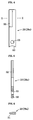
- the hammer member 29 (a first hammer member 29a) is a rod-shaped body having a flat, rectangular cross-section, on a base end edge of which a recess 50 is formed.
- a blade section (crushing blade) 25 is formed on one long edge of the hammer member 29 on the front end side.
- a through-hole 53 is formed near the recess 50.
- a through-hole (not shown) is provided in each circular plate 48.
- a bolt member (not shown) is inserted through the through-hole in the circular plates 48, the through-hole 53 in the hammer members 29, and the spacer 49 from an outward direction of a circular plate 49 on an outer side.
- a nut member 55 (see Fig. 1 ) is screwed onto a threaded end section of the bolt member projecting outward from a circular plate 48 on the other outer side.
- the recess 50 formed on the hammer members 29a is fitted onto an outer circumferential surface of the rotation shaft 45.
- a hammer member assembly is configured by four hammer members 29 (29a) being arranged along an axial direction of the rotation shaft 45. As shown in Fig. 1 , four hammer member assemblies are placed along a circumferential direction at a pitch of 90 degrees.
- Support legs 56 and 57 are disposed on both surface sides of the casing 21. End sections of the rotation shaft 45 are supported by the support legs 56 and 57 with bearing members 58 and 59 therebetween, such that the rotation shaft 45 can rotate freely.
- One end section of the rotation shaft 45 is connected to an output shaft of a driving motor (not shown), with an interlocking mechanism 60 including a belt member therebetween. As a result, when the driving motor is driven, driving force from the driving motor rotates the rotation shaft 45, via the interlocking mechanism 60.
- each fixed blade 47 is a U-shaped body including a first blade 61, a second blade 62, and a connecting piece 63 that connects the first blade 61 and the second blade 62.
- a plurality of fixed blades 47 are fixed onto a planar holding plate 64 and a curved holding plate 65 (see Fig. 7 and Fig. 8 ).
- the planar holding plate 64 is fixed onto a bottom surface of the top wall 31a of the casing 21.
- Each fixed blade 47 (47a) fixed onto the planar holding plate 64 is screwed onto the top wall 31a of the casing 21 by a bolt member 66 that is inserted into the connecting piece 63 and the planar holding plate 64.
- the plurality of fixed blades 47 fixed onto the planar holding plate 64 project downward, into the crushing chamber 26.
- a blade tip 67 of the first blades 61 and the second blades 62 on the top wall 31a side face the opening 40 side.
- the curved holding plate 65 is formed into an arc that is a radius of curvature along (facing) the circular trajectory.
- Plate fitting grooves 66 are formed on the casing 21 along the circular trajectory, on an outer diameter side of the circular trajectory.
- the curved holding plate 65 is fitted into the plate fitting grooves 66.
- the plate fitting grooves 66 are curved grooves respectively formed on a front wall 31b and a back wall 31c.
- the curved holding plate 65 includes a base plate 70, short-edge frames 71a and 71b, and long-edge frames 72a and 72b.
- the short-edge frames 71a and 71b are disposed on both short-edge sides of an inner surface (surface on the side on which the fixed blades 47 project) of the base plate 70.
- the long-edge frames 72a and 72b are disposed on both long-side edges of the inner surface of the base plate 70.
- One fixed blade 47b is disposed on one long-edge frame 72a side.
- Two fixed blades 47b are disposed on the other long-edge frame 72b side.
- a pair of curved holding plates 65 is provided.
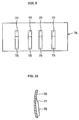
- a discharge plate 73 such as that shown in Fig. 11 and Fig. 12 , is disposed between the curved holding plates 65. Therefore, the discharge plate 73 is an arc-shaped body corresponding to the circular trajectory of the front end edge of the hammer members 29. Numerous discharge holes (punched holes) 74 are provided in the discharge plate 73.
- the discharge plate 73 is fitted into the plate fitting grooves 66 and placed below the rotation shaft 45. In other words, the lower discharge opening 23 is formed between the curved holding plates 65. The discharge plate 73 is placed in the lower discharge opening 23.
- a guide body 75 is disposed on a downstream side (lower side) of the guide path 20, as shown in Fig. 1 .
- the guide body 75 lifts the object to be crushed to the crushing chamber 26 side.
- the guide body 75 is integrally fixed onto a curved holding plate 76.
- the curved holding plate76 is formed into an arc that is a radius of curvature along (facing) the circular trajectory of the front end edge of the hammer members 29.
- the guide body 75 is a block piece that extends in the width direction of the plate.
- An angled surface 77 is formed on an upper end edge of the guide body 75.
- Four guide bodies 75 are arranged on the curved holding plate 76 along the longitudinal direction at a predetermined pitch.
- the guide bodies 75 are arranged on the downstream side (lower side) of the guide path 20 by the curved holding plate 76 being fitted into the plate grooves 66.
- the guide bodies 75, the fixed blades 47b, the discharge plate 73, and the fixed blades 47b are successively disposed from the downstream side of the guide path 20 towards the opening 40.
- the blade section 52 of each hammer member 29 passes between the guide bodies 75 and passes between the first blade 61 and the second blade of the fixed blades 47a on the top wall 31 a side.
- the blade section 52 of three hammer members 29 on the inner side passes between the first blade 61 and the second blade of the fixed blades 47b.
- the blade section 52 of the two hammer members 29 on the outer sides passes through the outer side of the fixed blades 47b on the outer sides.
- the blade tip 67 of each fixed blade 47b faces the guide body 75 side.
- the opening 40 forms a rough 120 degree angle.
- Flange sections 80 and 81 are respectively provided on a vertical direction opening end and an orthogonal direction opening end of the front wall 31b.
- Flange sections 82 and 83 are respectively provided on a vertical direction opening end and an orthogonal direction opening end of the back wall 31c.
- Ribs 84 and 85 are respectively formed on an intermediate section in a vertical direction and a counter-opening end section of the front wall 31 b.
- the lid member 32 includes a front wall 87, a back wall 88, and a peripheral wall 89.
- a lower end section of the lid member 32 is pivotally connected to the main body 31 of the casing 21 by a hinge section 90, such that the lid member 32 can swing as indicated by arrows C and D.
- the peripheral wall 89 includes a first wall 89a that rises from the hinge section 90, a second wall 89b that is connected to the first wall 89a, a third wall 89c that is connected to the second wall 89b, and a fourth wall 89d that is connected to the third wall 89c.
- the front wall 87 is fan-shaped.
- Flange sections 91 and 92 are respectively provided on a first end surface corresponding to a vertical direction opening end surface of the front wall 31 b of the casing 21 and a second end wall corresponding to the orthogonal direction opening end of the first wall 31b of the casing 21.
- the back wall 88 is also fan-shaped.
- Flange sections (not shown) are respectively formed on a first end wall corresponding to a vertical direction opening end surface of the back wall 31c of the casing 21 and a second end surface corresponding to the orthogonal direction opening end of the back wall 31c of the casing 21.
- the flange sections 91 and 92 of the front wall 87 of the lid member 32 can come into contact with the flange sections 80 and 81 of the front wall 31b of the casing 21.
- the flange sections of the back wall 88 can come into contact with the flange sections 82 and 83 of the back wall 31 c of the casing 21.
- the lid member 32 is in a closed state when the flange sections are in a contacting state.
- the opening end on the opening 40 side of the plate fitting grooves 66 is sealed.
- Each plate 65, 73, and 76 fitted into the plate grooves 66 can be prevented from becoming detached towards the opening side. Detachment of each plate 65, 73, and 76 towards the side counter to the opening is restricted by a counter-opening side end of the plate fitting grooves 66. Therefore, when the lid member 32 is in the closed state, each plate 65, 73, and 76 can be fixed at a fixed position.
- a plurality of crushing assisting projections 95 are provided on the inner surface of the peripheral wall 89 of the lid member 32.
- the crushing assisting projections 95 are bars having a square to rectangular cross-section that extend in a horizontal direction.
- the crushing assisting projections 95 are arranged on the inner surface of the peripheral wall 89, along the peripheral wall 89 at a predetermined pitch.
- a handle 99 is provided on the lid member 32 to allow opening and closing operations.
- a crushing method using the crusher configured as described above will be described.
- the shifting means 35 is switched to the state indicated by the phantom lines in Fig. 1 or, in other words, a state in which the loading opening 22 is completely open, as shown in Fig. 3b .
- the sheet-shaped object to be crushed is loaded from the loading opening 22.
- the sheet-shaped object enters the crushing chamber 26 along the angled surface 20a of the guide path 20.
- the rotation shaft 45 is rotated, and the hammer members 29 are rotated in a direction indicated by arrow A in Fig. 1 .
- the object to be crushed is lifted towards the crushing chamber 26 side by the guide bodies 75 provided on the downstream side of the loading opening 22.
- the sheet-shaped object that descends along the angled surface 20a is guided by the angled surface 77 of the guide bodies 75 and lifted from the angled surface 20a. Therefore, the rotating hammer members 29 strike the sheet-shaped object and cut the sheet-shaped object with the blade tips.
- the hammer members 29 catch the cut pieces.
- the fixed blades 47b on the lower discharge opening side and the fixed blades 47a on the top wall 31 a side perform operations such as further cutting the cut pieces into smaller pieces, and releasing the cut pieces.
- the front end edges of the hammer members 29 pass near the crushing assisting projections 95 on the lid member 32.
- the cut pieces are mashed by the front end edges of the hammer members 29 and the crushing assisting projections 95, and become a crushed object.
- the crushed object is discharged from the discharge holes 74 in the discharge plate 73 provided in the lower discharge opening 23 into a product chamber (not shown) disposed in a lower section of the casing 21.
- the product chamber is in a vacuum state by a suction device (not shown). In other words, because the product chamber is in the vacuum state, the object to be crushed that is loaded into the upper loading opening 22 is suctioned into the crushing chamber 26, crushed in the crushing chamber 26, and the crushed object is discharged into the product chamber.
- the crushed object is also compressed in the product chamber.
- the position of the shifting plate 36 of the shifting means 35 is switched to the state indicated by the broken lines in Fig. 1 .
- the shifting plate 36 is visible from the loading opening 22, as shown in Fig. 3A .
- the plastic block object is loaded into the loading opening 22 in this state.
- the plastic block object is guided by the angled surface 41 and enters the crushing chamber 26.
- the plastic block object drops in a roughly vertical direction and enters the crushing chamber 26.
- the object to be crushed enters the crushing chamber 26 along a direction of a tangent of the circular trajectory formed by the rotation of the hammer members 29. Therefore, when the object to be crushed enters the crushing chamber 26, the object to be crushed becomes meshed between the hammer members 29. As a result, the object to be crushed does not thrown by the hammer members 29.
- the baffle plate 98 made of an elastic material, such as rubber or resin, hangs from the top wall 31a of the casing main body 31. Therefore, even should the object to be crushed be thrown, the object to be crushed is returned to the crushing chamber by the baffle plate 98.
- the rotating hammer members 29 strike the object to be crushed and cut the object to be crushed with the blade tips.
- the hammer members 29 catch the cut pieces.
- the fixed blades 47b on the lower discharge opening side and the fixed blades 47a on the top wall 31 a side perform operations such as further cutting the cut pieces into smaller pieces, and releasing the cut pieces. Furthermore, the cut pieces are mashed by the front end edges of the hammer members 29 and the crushing assisting projections 95, and become the crushed object. Because the product chamber is in the vacuum state, the object to be crushed that is loaded into the upper loading opening 22 is suctioned into the crushing chamber 26, crushed in the crushing chamber 26, and the crushed object is discharged into the product chamber.
- the object to be crushed can be lifted towards the crushing chamber 26 side by the guide bodies 75 provided on the downstream side of the guide path 20, allowing the object to be crushed to come into contact with the hammer members 29. In other words, the object to be crushed no longer attaches itself to the inner surface of the crushing chamber 26. Therefore, the object to be crushed can be stably crushed.
- crushed objects larger than the diameter of the discharge holes 74 are not discharged.
- the crushed object remains in the crushing chamber 26 and are further crushed by the hammer members 29 and the fixed blades 47. Therefore, only crushed objects crushed to become smaller than the hole diameter of the discharge holes 74 are allowed to be discharged outside.
- the fixed blades 47 and the guide bodies 75 are respectively attached to the curbed holding plates 65 and 76, handleability of the fixed blades 47 and the guide bodies 75 is excellent.
- the discharge plate 73, and the plates 65 and 76 including the fixed blades 47 and the guide bodies 75 can be mounted on the casing 21.
- the fixed blades 47, the guide bodies 75 and the like can be easily set.
- mounting operations of the plates 65 and 76 can be performed through the opening 40 provided in the casing 21.
- Each plate 65 and 76 attached to the plate fitting grooves 66 can be fixed by the opening 40 being in the closed state by the lid member 32.
- the fixed blades 47, the guide bodies 75, and the like can be set at fixed positions as follows.
- the curved holding plates 65 and 76, on which the fixed blades 47 and the guide bodies 75 are respectively mounted, is fitted into the plate fitting grooves 66 on the casing 21 while the opening 40 is in an open state.
- the lid member 32 is placed in the closed state.
- the each plate 65 and 76 is released from the fixed state.
- the discharge plate 73, and the plates 65 and 76 including the fixed blades 47 and the guiding bodies 75 can be removed.
- the crusher can be used stably over a long period of time, contributing to reduction in running costs.
- the shifting means 35 can shift the loading direction into the crushing chamber 26 based on the type of object to the crushed that is loaded into the loading opening 22. Therefore, various types of objects to be crushed can be handled by a single crusher. Significant cost reduction can be achieved.
- crushing can be performed regardless of whether the object to be crushed is soft paper, such as an account book, or a hard substrate. Recording media storing various pieces of information (such as personal information) can be crushed to a non-reproducible state.
- paper is shredded by an existing shredder, fibers in the paper are finely cut, resulting in poor recyclability.
- the fibers in the paper remain relatively intact. Therefore, recyclability is excellent.
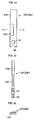
- the hammer member 29 can be that shown in Fig. 14 to Fig. 16 .
- a hammer member (second hammer member) 29b has a planar hammer section 100 on a front end side and a crushing blade 101 in the center.
- the recess 50 that fits onto the outer circumferential surface of the rotating shaft 45 is also formed on the base end edge of the hammer member 29b, in addition to the through-hole 53 for attaching the hammer member 29b provided near the recess 50.
- the hammer members 29b can also be easily attached to the rotation shaft 45 in a short amount of time.
- the hammer members 29b can rotate integrally with the rotation shaft 45.
- the planar hammer section 100 on the front end side can strike the object to be crushed, shredding the object. Tape and the like that becomes tangled with the hammer members 29b in the center of the crushing chamber 26 can be cut (shorn).
- the hammer member 29b shown in Fig. 14 to Fig. 16 is optimal for crushing cassette tapes.
- the hammer member 29a shown in Fig. 4 to Fig. 6 can also crush cassette tapes.
- the hammer member 29b shown in Fig. 14 to Fig. 16 can also crush paper.
- Each hammer member 29a and 29b can be easily attached and detached in a short amount of time. Therefore, the hammer member 29b shown in Fig. 14 and the like and the hammer member 29a shown in Fig. 4 and the like can be provided. The hammer members 29 can be interchanged based on the object to be crushed.
- hammer members 29 can be interchanged based on the type of object to the crushed.
- the optimal hammer member 29 can be used to crush the object to be crushed. Crushing precision of the crusher is enhanced.
- the object to be crushed can be various objects, such as substrates (substrates mounted on an electrical component and the like), magnetic tape recording media including cassette tapes, optical recording media, and paper.
- a single crusher can crush objects ranging from hard objects (such as substrates) to soft objects (such as paper). Therefore, although the crusher to be used is conventionally selected based on the material, shape, hardness and the like of the loaded object to be crushed that is loaded, a single crusher can perform crushing for a wide range of purposes, from hard objects to soft objects, when the crusher of the present invention is used. Therefore, equipment cost can be reduced and running costs can be reduced, thereby reducing overall processing costs. Moreover, excellent protection of personal information and recyclability can be achieved.
- the present invention is not limited to the above-described embodiment.
- the present invention is not limited to the above-described embodiment.
- Various modifications can be made.
- the number of hammer member assemblies and the number of hammer members 29 in each hammer member assembly can be arbitrarily increased and decreased.
- the number of fixed blades 47 arranged on a single plate 64 and plate 65 can also be arbitrarily increased and decreased.
- the number of plates 65 fitted into the plate fitting grooves 66 and the circumferential direction length of the plate 65 can be arbitrarily set.
- Discharge holes can also be provided on the plate 65 on which the fixed blades 47 are fixed.
- the crushed object can be discharged from the discharge holes into the product chamber (crushed object storage chamber).
- the discharge holes in this instance and the discharge holes 74 in the discharge plate are not limited to circular holes. Elliptical holes, triangular holes, rectangular holes, and the like can be used. Slit-shaped holes and the like can also be used.
- the crushing assisting projections 95 are arranged on the lid member 32.
- the crushing assisting projections 95 can be omitted.
- the fixed blades 47 can be placed instead of the crushing assisting projections 95.
- rotation frequency of the hammer members 29 can be changed based on the type of object to be crushed and the like.
- the rotation frequency can be changed between the initial stage of crushing and the final stage of crushing. In this instance, the rotation frequency can be slow at the initial stage of crushing, subsequently becoming gradually faster.
- the hammer members 29 can operate for a predetermined amount of time at a low speed at the initial stage of crushing, subsequently switching to a medium speed. The hammer members 29 can then operate for a predetermined amount of time at the medium speed, subsequently switching to a high speed. The hammer members 29 can then operate for a predetermined amount of time at the high speed.
- the object to be crushed As a result of the object to be crushed being loaded into the loading opening, the object to be crushed, such as paper, magnetic tape recording media including cassette tapes, optical recording media, and substrates, is lifted by the guiding bodies without attaching itself to the inner surface of the crushing chamber. The object to be crushed is then crushed by the hammer members.
Landscapes
- Engineering & Computer Science (AREA)
- Food Science & Technology (AREA)
- Crushing And Pulverization Processes (AREA)
Claims (8)
- Zerkleinerungsmaschine in der Hammerelemente (29), die sich von einer Rotationswelle (45) in eine radiale Richtung erstrecken und mit der Rotation der Rotationswelle (45) rotieren, in einem Gehäuse (21) beherbergt sind, das enthält eine obere Zuführöffnung (22) zum Zuführen eines Objekts, das zerkleinert werden soll, und eine untere Entladeöffnung (23) zum Entladen eines zerkleinerten Objekts, wobei in dem Gehäuse (21) feste Klingen (47) an einer äußeren Durchmesserseite der Hammerelemente (29) angeordnet sind, und wobei die Hammerelemente (29) und die festen Klingen (47) das Objekt, das zerkleinert werden soll, zerkleinern, wenn die Hammerelemente (29) rotiert werden, wobei die Zerkleinerungsmaschine dadurch gekennzeichnet ist, dass sie umfasst:eine Öffnung (40) in dem Gehäuse (21), wobei die Öffnung (40) durch Öffnungs- oder Schließabläufe eines Abdeckelements (32) und Plattenpassnuten, die entlang einer kreisförmigen Bogenfläche des Gehäuses (21) entsprechend einer kreisförmigen Trajektorie, der die vorderen Endkanten der Hammerelemente während der Rotation folgen, geöffnet und geschlossen werden kann, undwobei die festen Klingen (47) an einer gekrümmten Halteplatte (65) angebracht sind und die gekrümmte Halteplatte (65) in die Plattenpassnuten (66) des Gehäuses (21) von der Öffnung (40) aus eingepasst ist.
- Zerkleinerungsmaschine gemäß Anspruch 1, wobei:eine Führungsbahn (20), die in dem Gehäuse (21) bereitgestellt ist, die das Objekt, das zerkleinert werden soll und das von der oberen Zuführöffnung (22) zugeführt wird, in eine Zerkleinerungskammer (26) führt, in der das Objekt, das zerkleinert werden soll, durch die Hammerelemente (29) und die festen Klingen (47) zerkleinert wird, undFührungskörper (75), die das Objekt, das zerkleinert werden soll, in Richtung der Zerkleinerungskammerseite anheben, an einer nachgelagerten Seite der Führungsbahn (20) bereitgestellt sind.
- Zerkleinerungsmaschine gemäß Anspruch 2, wobei:eine Öffnung (40), die durch Öffnungs- oder Schließabläufe eines Abdeckelements (32) und Plattenpassnuten (66), die entlang einer kreisförmigen Bogenfläche entsprechend einer kreisförmigen Trajektorie, der die vorderen Endkanten der Hammerelemente (29) während der Rotation folgen, geöffnet und geschlossen werden kann, an dem Gehäuse (21) gebildet sind, undwobei die Führungskörper (75) an einer gekrümmten Halteplatte (76) angebracht sind und die gekrümmte Halteplatte (76) in die Plattenpassnuten (66) von der Öffnung (40) aus eingepasst ist.
- Zerkleinerungsmaschine gemäß Anspruch 1 oder 3, wobei eine gekrümmte Entladeplatte (73) einschließlich zahlreicher Löcher (74) zum Entladen des zerkleinerten Objekts in die Plattenpassnuten (66) eingepasst ist und wobei die gekrümmte Entladeplatte (73) in der unteren Entladeöffnung (23) platziert ist.
- Zerkleinerungsmaschine gemäß irgendeinem der Ansprüche 1, 3 und 4, wobei jede Platte (65, 73, 76), die in die Plattenpassnuten (66) eingepasst ist, in einer festen Position befestigt ist, wenn die Öffnung (40) in dem Gehäuse (21) durch das Abdeckelement (32) in einem geschlossenen Zustand ist.
- Zerkleinerungsmaschine gemäß irgendeinem der Ansprüche 1, 3, 4 und 5, wobei eine Vielzahl von Zerkleinerungshilfsvorsprüngen (95) an einer Innenfläche des Abdeckelement (32) bereitgestellt ist.
- Zerkleinerungsmaschine gemäß irgendeinem der Ansprüche 1 bis 6, wobei ein Verschiebemittel (35), das eine Zuführrichttung in die Zerkleinerungskammer (26) verschiebt, basierend auf einem Typ des Objekts, das zerkleinert werden soll und das in die obere Zuführöffnung (22) geladen wird, bereitgestellt ist.
- Zerkleinerungsmaschine gemäß irgendeinem der Ansprüche 1 bis 7, wobei ein Hammerelement (29) wenigstens ein erstes Hammerelement (29a) mit einer Zerkleinerungsklinge (52) an einer Vorderendseite, und ein zweites Hammerelement (29b) enthält, das einen flachen Hammerabschnitt (100) an einer Vorderendseite und eine Zerkleinerungsklinge (101) in der Mitte aufweist, wobei das erste Hammerelement (29a) und das zweite Hammerelement (29b) wahlweise basierend auf einem Typ des Objekts, das zerkleinert werden soll, angebracht werden können.
Applications Claiming Priority (2)
| Application Number | Priority Date | Filing Date | Title |
|---|---|---|---|
| JP2006202050A JP4412558B2 (ja) | 2006-07-25 | 2006-07-25 | 粉砕機 |
| PCT/JP2007/064231 WO2008013091A1 (fr) | 2006-07-25 | 2007-07-19 | Broyeur |
Publications (3)
| Publication Number | Publication Date |
|---|---|
| EP2045016A1 EP2045016A1 (de) | 2009-04-08 |
| EP2045016A4 EP2045016A4 (de) | 2014-08-27 |
| EP2045016B1 true EP2045016B1 (de) | 2016-09-07 |
Family
ID=38981403
Family Applications (1)
| Application Number | Title | Priority Date | Filing Date |
|---|---|---|---|
| EP07790985.1A Active EP2045016B1 (de) | 2006-07-25 | 2007-07-19 | Zerkleinerungsvorrichtung |
Country Status (7)
| Country | Link |
|---|---|
| US (1) | US8152085B2 (de) |
| EP (1) | EP2045016B1 (de) |
| JP (1) | JP4412558B2 (de) |
| KR (1) | KR101280557B1 (de) |
| CN (1) | CN101495238A (de) |
| CA (1) | CA2658957A1 (de) |
| WO (1) | WO2008013091A1 (de) |
Families Citing this family (37)
| Publication number | Priority date | Publication date | Assignee | Title |
|---|---|---|---|---|
| JP5225719B2 (ja) * | 2008-03-21 | 2013-07-03 | 晃立工業株式会社 | 粉砕機 |
| JP5225718B2 (ja) * | 2008-03-21 | 2013-07-03 | 晃立工業株式会社 | 粉砕機 |
| AU2010254320B2 (en) * | 2009-05-23 | 2014-08-14 | Scott Anthony Wozny | Hard drive destruction system |
| US8152081B2 (en) * | 2009-08-12 | 2012-04-10 | Harris Waste Management Group, Inc. | Comminuting machine containment system |
| DE202009016107U1 (de) * | 2009-11-25 | 2010-03-25 | Sib Strautmann Ingenieurbüro Gmbh | Vorrichtung zum mechanischen Behandeln von Verpackungsgebinden |
| JP5710463B2 (ja) * | 2011-12-27 | 2015-04-30 | 株式会社キンキ | 実装部品の剥離装置 |
| US20130200188A1 (en) * | 2012-02-01 | 2013-08-08 | Vermeer Manufacturing Company | Sizing screens for comminuting machines |
| US9186684B2 (en) | 2012-04-16 | 2015-11-17 | Harris Waste Management Group, Inc. | Comminuting machine drive system |
| JP2014073463A (ja) * | 2012-10-04 | 2014-04-24 | Miken:Kk | ハンマークラッシャー |
| NL2009580C2 (nl) | 2012-10-05 | 2014-04-08 | Galiën Hannie | Verkleiner voor het verkleinen van grof materiaal en werkwijze daarvoor. |
| CN102921509A (zh) * | 2012-11-14 | 2013-02-13 | 铜陵市久泰重型工矿设备有限公司 | 锤式破碎机入料口挡粉尘装置 |
| HRP20240533T1 (hr) * | 2013-04-23 | 2024-07-05 | Eggersmann Ingenieurgesellschaft Mbh | Uređaj za usitnjavanje rasutog materijala i postupak za njega |
| JP6329735B2 (ja) * | 2013-07-08 | 2018-05-23 | 新日鉄住金エンジニアリング株式会社 | スラッジ塊破砕機 |
| US10380764B2 (en) * | 2013-12-18 | 2019-08-13 | Cognex Corporation | System and method for performing vision system planar hand-eye calibration from straight line features |
| EP3002061B1 (de) * | 2014-05-30 | 2019-07-10 | Koritsu Industries Co. Ltd. | Pulverisierer |
| CN104759336B (zh) * | 2015-04-02 | 2017-11-10 | 章丘市宇龙机械有限公司 | 一种双层破碎机 |
| CN104772190B (zh) * | 2015-05-09 | 2017-10-10 | 蚌埠玻璃工业设计研究院 | 一种平板玻璃碎玻璃破碎装置 |
| JP6656863B2 (ja) * | 2015-09-26 | 2020-03-04 | 株式会社奈良機械製作所 | 回転刃体及び粉砕機 |
| KR20170047477A (ko) * | 2015-10-22 | 2017-05-08 | 코닝정밀소재 주식회사 | 글라스 파쇄장치 |
| JP6619217B2 (ja) * | 2015-11-26 | 2019-12-11 | オリンパス株式会社 | 顕微鏡システムとその制御方法 |
| CN106423400B (zh) * | 2016-11-24 | 2019-01-08 | 南通天龙畜产品有限公司 | 全封闭高速管式肠皮粉碎机 |
| JP2019173200A (ja) * | 2018-03-28 | 2019-10-10 | セイコーエプソン株式会社 | 解繊処理装置、および、繊維原料再生装置 |
| CN112203770B (zh) | 2018-05-23 | 2023-01-03 | 维米尔制造公司 | 用于粉碎散料的切碎机 |
| JP6476532B1 (ja) * | 2018-06-12 | 2019-03-06 | 三菱重工環境・化学エンジニアリング株式会社 | 二軸破砕機 |
| CN108940475A (zh) * | 2018-07-06 | 2018-12-07 | 董玉凤 | 一种食品加工机用研磨装置 |
| CN109760973B (zh) * | 2019-03-07 | 2021-06-18 | 东阳市天齐知识产权运营有限公司 | 废纸回收装置 |
| US11666921B2 (en) * | 2019-06-10 | 2023-06-06 | U.S. Mining, Inc. | Systems and methods for crushing clay, transporting clay, and processing clay |
| US20210002089A1 (en) * | 2019-07-01 | 2021-01-07 | Daniel Charhut | System and mechanism for bottom ash feed regulation to a low capacity conveyor |
| CN110354954B (zh) * | 2019-08-15 | 2024-06-14 | 广西叶茂机电自动化有限责任公司 | 一种硫磺定量粉碎机 |
| CN112958237B (zh) * | 2021-01-29 | 2022-06-07 | 福建省明辉机械制造有限公司 | 一种装配式木浆粉碎机 |
| US20220305498A1 (en) * | 2021-03-26 | 2022-09-29 | Thomas Delahunty | Media declassification device |
| JP7713323B2 (ja) * | 2021-07-01 | 2025-07-25 | 富士車輌株式会社 | 破砕装置 |
| CN113617462B (zh) * | 2021-08-10 | 2022-07-29 | 福州巨业食品有限公司 | 一种丝网状农产品打散装置 |
| CN115007286A (zh) * | 2022-05-20 | 2022-09-06 | 铜陵有色兴铜机电制造有限公司 | 带有可拆卸式辊刀的破碎机 |
| CN115055259B (zh) * | 2022-08-16 | 2022-12-27 | 福建省泉州市海珍食品有限公司 | 一种蚝肉碎料加工装置 |
| CN116550429B (zh) * | 2023-07-11 | 2023-08-29 | 山东和康源集团有限公司 | 一种畜禽饲料加工装置及加工方法 |
| KR102740597B1 (ko) * | 2023-11-29 | 2024-12-10 | 한국건설기술연구원 | 건식 안전형 절단구성을 가지는 음식물 쓰레기 투입장치, 및 이를 구비한 음식물 쓰레기 진공이송 처리시스템 |
Family Cites Families (34)
| Publication number | Priority date | Publication date | Assignee | Title |
|---|---|---|---|---|
| US553163A (en) * | 1896-01-14 | Emile jolicard | ||
| US1648747A (en) * | 1926-01-30 | 1927-11-08 | Wolf Company | Pulverizer |
| US1975406A (en) * | 1931-08-10 | 1934-10-02 | William F Reschke | Feed mill |
| FR1083913A (fr) * | 1953-09-22 | 1955-01-13 | Perfectionnements aux broyeurs à marteaux | |
| US2954176A (en) * | 1956-01-30 | 1960-09-27 | Knox D Cole | Variable feed mill throat for admitting whole bales of hay |
| DE1169262B (de) * | 1960-09-15 | 1964-04-30 | Naturizer Co | Schlagmuehle zur Zerkleinerung, insbesondere von Muell |
| FR1277341A (fr) * | 1960-10-17 | 1961-12-01 | Anciens Etablissements Emile R | Broyeurs à marteaux |
| JPS5134132B2 (de) | 1972-09-08 | 1976-09-24 | ||
| SE399917B (sv) * | 1975-01-31 | 1978-03-06 | Kamas Ind Ab | Forfarande och anordning for astadkommande av fluffat fibermaterial |
| US4061277A (en) * | 1976-09-20 | 1977-12-06 | Sivyer Steel Corporation | Shredder with grate cartridge |
| DE2657196C3 (de) * | 1976-12-17 | 1980-07-31 | Lindemann Maschinenfabrik Gmbh, 4000 Duesseldorf | Vorrichtung zum Zerkleinern von insbesondere Altpapier |
| US4350307A (en) * | 1980-02-01 | 1982-09-21 | Olson Gerald R | Two-sided magnetized diverting plate for hammermill |
| US4533088A (en) * | 1983-08-03 | 1985-08-06 | American Pulverizer Company | Frozen coal cracker |
| DE3536440C1 (de) * | 1985-10-12 | 1987-03-26 | Hoffmann Karl Heinz | Ringspaltmuehle |
| JP2540919B2 (ja) | 1988-10-07 | 1996-10-09 | 味の素株式会社 | 油揚げの製造方法 |
| JPH048998Y2 (de) * | 1990-01-17 | 1992-03-06 | ||
| JPH04938U (de) * | 1990-04-18 | 1992-01-07 | ||
| JPH04938A (ja) | 1990-04-18 | 1992-01-06 | Nec Corp | データ収集装置 |
| DE4128373A1 (de) | 1991-08-27 | 1993-03-04 | Rudi Goldau | Verfahren und vorrichtung zum zerkleinern von gut |
| US5390862A (en) * | 1992-06-12 | 1995-02-21 | 7/7/77 Incorporated | Apparatus for chipping and grinding tree limbs |
| DE4311435B4 (de) * | 1993-04-07 | 2005-10-06 | Werner Doppstadt | Zerkleinerungsmaschine mit Nachzerkleinerungskorb |
| DE4343406C1 (de) * | 1993-12-18 | 1994-12-08 | Noell Serv & Maschtechn Gmbh | Prallmühle mit schwenkbarer Mahlbahn |
| JP3126091B2 (ja) * | 1994-05-10 | 2001-01-22 | チヨダセラ株式会社 | ボードの粉砕処理装置 |
| JP3459122B2 (ja) * | 1994-09-16 | 2003-10-20 | 日本スピンドル製造株式会社 | ガラス瓶粉砕機 |
| JPH08117634A (ja) | 1994-10-27 | 1996-05-14 | Japan Steel Works Ltd:The | ブリッジ防止手段を備えた粉砕機 |
| JP2904400B2 (ja) | 1994-12-15 | 1999-06-14 | 株式会社栗本鐵工所 | 横型ハンマークラッシャーのグレートバー |
| CA2161610A1 (en) * | 1995-02-01 | 1996-08-02 | Usman Firdaus | Chipper shredder |
| US5657933A (en) * | 1995-08-16 | 1997-08-19 | Williams; Robert M. | Adjustable feed plate for paper shredder |
| JPH0957132A (ja) | 1995-08-23 | 1997-03-04 | Techno Power:Kk | 生ゴミ処理用洗浄攪拌破砕装置 |
| US5695134A (en) * | 1996-04-10 | 1997-12-09 | Williams; Robert M. | Material reducing hammer mill with internal air circulating fan |
| JP3362352B2 (ja) * | 1999-07-26 | 2003-01-07 | 秋木機械株式会社 | 破砕装置 |
| JP4041641B2 (ja) | 1999-09-17 | 2008-01-30 | Ntn株式会社 | 固定型等速自在継手 |
| JP3145089B1 (ja) * | 2000-08-31 | 2001-03-12 | 有限会社大東土木 | 磨砕機 |
| JP2004230295A (ja) * | 2003-01-30 | 2004-08-19 | Teppu Engineering Kk | 製砂装置 |
-
2006
- 2006-07-25 JP JP2006202050A patent/JP4412558B2/ja active Active
-
2007
- 2007-07-19 EP EP07790985.1A patent/EP2045016B1/de active Active
- 2007-07-19 US US12/374,784 patent/US8152085B2/en active Active
- 2007-07-19 KR KR1020097003617A patent/KR101280557B1/ko active Active
- 2007-07-19 CN CNA2007800282167A patent/CN101495238A/zh active Pending
- 2007-07-19 CA CA002658957A patent/CA2658957A1/en not_active Abandoned
- 2007-07-19 WO PCT/JP2007/064231 patent/WO2008013091A1/ja not_active Ceased
Also Published As
| Publication number | Publication date |
|---|---|
| WO2008013091A1 (fr) | 2008-01-31 |
| JP2008023500A (ja) | 2008-02-07 |
| EP2045016A4 (de) | 2014-08-27 |
| EP2045016A1 (de) | 2009-04-08 |
| US8152085B2 (en) | 2012-04-10 |
| US20100006683A1 (en) | 2010-01-14 |
| JP4412558B2 (ja) | 2010-02-10 |
| CA2658957A1 (en) | 2008-01-31 |
| KR101280557B1 (ko) | 2013-07-02 |
| KR20090033489A (ko) | 2009-04-03 |
| CN101495238A (zh) | 2009-07-29 |
Similar Documents
| Publication | Publication Date | Title |
|---|---|---|
| EP2045016B1 (de) | Zerkleinerungsvorrichtung | |
| US7757979B2 (en) | Hammermill hammer with pin-hole insert | |
| US7677483B2 (en) | Substrate destruction apparatus with shared rotating shaft | |
| JP3893353B2 (ja) | 破砕装置 | |
| JP5225719B2 (ja) | 粉砕機 | |
| US6944926B2 (en) | Method for disassembling refrigerator, compressing device, and device for disassembling the same | |
| JP5442309B2 (ja) | 砕氷機 | |
| JP5225718B2 (ja) | 粉砕機 | |
| JP4319086B2 (ja) | 木質系粉砕装置 | |
| KR102529172B1 (ko) | 문서 세단기 | |
| CN101534951B (zh) | 粉碎机、驱动部的安装方法 | |
| JP3459122B2 (ja) | ガラス瓶粉砕機 | |
| JP2002153764A (ja) | ハンマシュレッダの細破砕ハンマ | |
| JP2008168196A (ja) | 廃タイヤ切断装置 | |
| JP2003159544A (ja) | 破袋装置 | |
| JP2006263655A (ja) | 破砕装置 | |
| KR100896348B1 (ko) | 문서세단기 회전축의 휨 방지장치 | |
| KR101732949B1 (ko) | 수목가지 파쇄 장치 | |
| JP4499010B2 (ja) | 衝撃式破砕機の打撃板固定装置。 | |
| JP4084813B2 (ja) | 粉砕機 | |
| JP2007167822A (ja) | 粉砕装置 | |
| CN214864166U (zh) | 一种防卡纸的碎纸机 | |
| JP3293329B2 (ja) | シュレッダ | |
| JPH11169737A (ja) | シュレッダー | |
| JP2008142652A (ja) | 破砕処理装置および搬送装置 |
Legal Events
| Date | Code | Title | Description |
|---|---|---|---|
| PUAI | Public reference made under article 153(3) epc to a published international application that has entered the european phase |
Free format text: ORIGINAL CODE: 0009012 |
|
| 17P | Request for examination filed |
Effective date: 20090122 |
|
| AK | Designated contracting states |
Kind code of ref document: A1 Designated state(s): AT BE BG CH CY CZ DE DK EE ES FI FR GB GR HU IE IS IT LI LT LU LV MC MT NL PL PT RO SE SI SK TR |
|
| AX | Request for extension of the european patent |
Extension state: AL BA HR MK RS |
|
| DAX | Request for extension of the european patent (deleted) | ||
| A4 | Supplementary search report drawn up and despatched |
Effective date: 20140728 |
|
| RIC1 | Information provided on ipc code assigned before grant |
Ipc: B02C 18/14 20060101ALI20140722BHEP Ipc: B02C 13/284 20060101ALI20140722BHEP Ipc: B02C 18/18 20060101ALI20140722BHEP Ipc: B02C 13/282 20060101ALI20140722BHEP Ipc: B02C 18/22 20060101ALI20140722BHEP Ipc: B02C 13/286 20060101ALI20140722BHEP Ipc: B02C 13/06 20060101AFI20140722BHEP Ipc: B02C 13/28 20060101ALI20140722BHEP |
|
| 17Q | First examination report despatched |
Effective date: 20150826 |
|
| GRAP | Despatch of communication of intention to grant a patent |
Free format text: ORIGINAL CODE: EPIDOSNIGR1 |
|
| INTG | Intention to grant announced |
Effective date: 20160404 |
|
| GRAS | Grant fee paid |
Free format text: ORIGINAL CODE: EPIDOSNIGR3 |
|
| GRAA | (expected) grant |
Free format text: ORIGINAL CODE: 0009210 |
|
| AK | Designated contracting states |
Kind code of ref document: B1 Designated state(s): AT BE BG CH CY CZ DE DK EE ES FI FR GB GR HU IE IS IT LI LT LU LV MC MT NL PL PT RO SE SI SK TR |
|
| REG | Reference to a national code |
Ref country code: GB Ref legal event code: FG4D |
|
| REG | Reference to a national code |
Ref country code: CH Ref legal event code: EP |
|
| REG | Reference to a national code |
Ref country code: IE Ref legal event code: FG4D |
|
| REG | Reference to a national code |
Ref country code: AT Ref legal event code: REF Ref document number: 826346 Country of ref document: AT Kind code of ref document: T Effective date: 20161015 |
|
| REG | Reference to a national code |
Ref country code: DE Ref legal event code: R096 Ref document number: 602007047846 Country of ref document: DE |
|
| REG | Reference to a national code |
Ref country code: LT Ref legal event code: MG4D |
|
| REG | Reference to a national code |
Ref country code: NL Ref legal event code: MP Effective date: 20160907 |
|
| PG25 | Lapsed in a contracting state [announced via postgrant information from national office to epo] |
Ref country code: FI Free format text: LAPSE BECAUSE OF FAILURE TO SUBMIT A TRANSLATION OF THE DESCRIPTION OR TO PAY THE FEE WITHIN THE PRESCRIBED TIME-LIMIT Effective date: 20160907 Ref country code: LT Free format text: LAPSE BECAUSE OF FAILURE TO SUBMIT A TRANSLATION OF THE DESCRIPTION OR TO PAY THE FEE WITHIN THE PRESCRIBED TIME-LIMIT Effective date: 20160907 |
|
| REG | Reference to a national code |
Ref country code: AT Ref legal event code: MK05 Ref document number: 826346 Country of ref document: AT Kind code of ref document: T Effective date: 20160907 |
|
| PG25 | Lapsed in a contracting state [announced via postgrant information from national office to epo] |
Ref country code: NL Free format text: LAPSE BECAUSE OF FAILURE TO SUBMIT A TRANSLATION OF THE DESCRIPTION OR TO PAY THE FEE WITHIN THE PRESCRIBED TIME-LIMIT Effective date: 20160907 Ref country code: LV Free format text: LAPSE BECAUSE OF FAILURE TO SUBMIT A TRANSLATION OF THE DESCRIPTION OR TO PAY THE FEE WITHIN THE PRESCRIBED TIME-LIMIT Effective date: 20160907 Ref country code: ES Free format text: LAPSE BECAUSE OF FAILURE TO SUBMIT A TRANSLATION OF THE DESCRIPTION OR TO PAY THE FEE WITHIN THE PRESCRIBED TIME-LIMIT Effective date: 20160907 Ref country code: GR Free format text: LAPSE BECAUSE OF FAILURE TO SUBMIT A TRANSLATION OF THE DESCRIPTION OR TO PAY THE FEE WITHIN THE PRESCRIBED TIME-LIMIT Effective date: 20161208 Ref country code: SE Free format text: LAPSE BECAUSE OF FAILURE TO SUBMIT A TRANSLATION OF THE DESCRIPTION OR TO PAY THE FEE WITHIN THE PRESCRIBED TIME-LIMIT Effective date: 20160907 |
|
| PG25 | Lapsed in a contracting state [announced via postgrant information from national office to epo] |
Ref country code: EE Free format text: LAPSE BECAUSE OF FAILURE TO SUBMIT A TRANSLATION OF THE DESCRIPTION OR TO PAY THE FEE WITHIN THE PRESCRIBED TIME-LIMIT Effective date: 20160907 Ref country code: RO Free format text: LAPSE BECAUSE OF FAILURE TO SUBMIT A TRANSLATION OF THE DESCRIPTION OR TO PAY THE FEE WITHIN THE PRESCRIBED TIME-LIMIT Effective date: 20160907 |
|
| PG25 | Lapsed in a contracting state [announced via postgrant information from national office to epo] |
Ref country code: AT Free format text: LAPSE BECAUSE OF FAILURE TO SUBMIT A TRANSLATION OF THE DESCRIPTION OR TO PAY THE FEE WITHIN THE PRESCRIBED TIME-LIMIT Effective date: 20160907 Ref country code: CZ Free format text: LAPSE BECAUSE OF FAILURE TO SUBMIT A TRANSLATION OF THE DESCRIPTION OR TO PAY THE FEE WITHIN THE PRESCRIBED TIME-LIMIT Effective date: 20160907 Ref country code: SK Free format text: LAPSE BECAUSE OF FAILURE TO SUBMIT A TRANSLATION OF THE DESCRIPTION OR TO PAY THE FEE WITHIN THE PRESCRIBED TIME-LIMIT Effective date: 20160907 Ref country code: IS Free format text: LAPSE BECAUSE OF FAILURE TO SUBMIT A TRANSLATION OF THE DESCRIPTION OR TO PAY THE FEE WITHIN THE PRESCRIBED TIME-LIMIT Effective date: 20170107 Ref country code: BG Free format text: LAPSE BECAUSE OF FAILURE TO SUBMIT A TRANSLATION OF THE DESCRIPTION OR TO PAY THE FEE WITHIN THE PRESCRIBED TIME-LIMIT Effective date: 20161207 Ref country code: PL Free format text: LAPSE BECAUSE OF FAILURE TO SUBMIT A TRANSLATION OF THE DESCRIPTION OR TO PAY THE FEE WITHIN THE PRESCRIBED TIME-LIMIT Effective date: 20160907 Ref country code: PT Free format text: LAPSE BECAUSE OF FAILURE TO SUBMIT A TRANSLATION OF THE DESCRIPTION OR TO PAY THE FEE WITHIN THE PRESCRIBED TIME-LIMIT Effective date: 20170109 Ref country code: BE Free format text: LAPSE BECAUSE OF FAILURE TO SUBMIT A TRANSLATION OF THE DESCRIPTION OR TO PAY THE FEE WITHIN THE PRESCRIBED TIME-LIMIT Effective date: 20160907 |
|
| REG | Reference to a national code |
Ref country code: DE Ref legal event code: R097 Ref document number: 602007047846 Country of ref document: DE |
|
| PG25 | Lapsed in a contracting state [announced via postgrant information from national office to epo] |
Ref country code: IT Free format text: LAPSE BECAUSE OF FAILURE TO SUBMIT A TRANSLATION OF THE DESCRIPTION OR TO PAY THE FEE WITHIN THE PRESCRIBED TIME-LIMIT Effective date: 20160907 |
|
| PLBE | No opposition filed within time limit |
Free format text: ORIGINAL CODE: 0009261 |
|
| STAA | Information on the status of an ep patent application or granted ep patent |
Free format text: STATUS: NO OPPOSITION FILED WITHIN TIME LIMIT |
|
| PG25 | Lapsed in a contracting state [announced via postgrant information from national office to epo] |
Ref country code: DK Free format text: LAPSE BECAUSE OF FAILURE TO SUBMIT A TRANSLATION OF THE DESCRIPTION OR TO PAY THE FEE WITHIN THE PRESCRIBED TIME-LIMIT Effective date: 20160907 |
|
| 26N | No opposition filed |
Effective date: 20170608 |
|
| PG25 | Lapsed in a contracting state [announced via postgrant information from national office to epo] |
Ref country code: SI Free format text: LAPSE BECAUSE OF FAILURE TO SUBMIT A TRANSLATION OF THE DESCRIPTION OR TO PAY THE FEE WITHIN THE PRESCRIBED TIME-LIMIT Effective date: 20160907 |
|
| REG | Reference to a national code |
Ref country code: CH Ref legal event code: PL |
|
| GBPC | Gb: european patent ceased through non-payment of renewal fee |
Effective date: 20170719 |
|
| REG | Reference to a national code |
Ref country code: IE Ref legal event code: MM4A |
|
| REG | Reference to a national code |
Ref country code: FR Ref legal event code: ST Effective date: 20180330 |
|
| PG25 | Lapsed in a contracting state [announced via postgrant information from national office to epo] |
Ref country code: CH Free format text: LAPSE BECAUSE OF NON-PAYMENT OF DUE FEES Effective date: 20170731 Ref country code: IE Free format text: LAPSE BECAUSE OF NON-PAYMENT OF DUE FEES Effective date: 20170719 Ref country code: GB Free format text: LAPSE BECAUSE OF NON-PAYMENT OF DUE FEES Effective date: 20170719 Ref country code: LI Free format text: LAPSE BECAUSE OF NON-PAYMENT OF DUE FEES Effective date: 20170731 |
|
| PG25 | Lapsed in a contracting state [announced via postgrant information from national office to epo] |
Ref country code: FR Free format text: LAPSE BECAUSE OF NON-PAYMENT OF DUE FEES Effective date: 20170731 |
|
| PG25 | Lapsed in a contracting state [announced via postgrant information from national office to epo] |
Ref country code: LU Free format text: LAPSE BECAUSE OF NON-PAYMENT OF DUE FEES Effective date: 20170719 |
|
| PG25 | Lapsed in a contracting state [announced via postgrant information from national office to epo] |
Ref country code: MT Free format text: LAPSE BECAUSE OF NON-PAYMENT OF DUE FEES Effective date: 20170719 |
|
| PG25 | Lapsed in a contracting state [announced via postgrant information from national office to epo] |
Ref country code: MC Free format text: LAPSE BECAUSE OF FAILURE TO SUBMIT A TRANSLATION OF THE DESCRIPTION OR TO PAY THE FEE WITHIN THE PRESCRIBED TIME-LIMIT Effective date: 20160907 Ref country code: HU Free format text: LAPSE BECAUSE OF FAILURE TO SUBMIT A TRANSLATION OF THE DESCRIPTION OR TO PAY THE FEE WITHIN THE PRESCRIBED TIME-LIMIT; INVALID AB INITIO Effective date: 20070719 |
|
| PG25 | Lapsed in a contracting state [announced via postgrant information from national office to epo] |
Ref country code: CY Free format text: LAPSE BECAUSE OF NON-PAYMENT OF DUE FEES Effective date: 20160907 |
|
| PG25 | Lapsed in a contracting state [announced via postgrant information from national office to epo] |
Ref country code: TR Free format text: LAPSE BECAUSE OF FAILURE TO SUBMIT A TRANSLATION OF THE DESCRIPTION OR TO PAY THE FEE WITHIN THE PRESCRIBED TIME-LIMIT Effective date: 20160907 |
|
| PGFP | Annual fee paid to national office [announced via postgrant information from national office to epo] |
Ref country code: DE Payment date: 20250729 Year of fee payment: 19 |