EP2045132A2 - Dispositif de support de commande, procédé de support de commande, et programme informatique - Google Patents
Dispositif de support de commande, procédé de support de commande, et programme informatique Download PDFInfo
- Publication number
- EP2045132A2 EP2045132A2 EP08016123A EP08016123A EP2045132A2 EP 2045132 A2 EP2045132 A2 EP 2045132A2 EP 08016123 A EP08016123 A EP 08016123A EP 08016123 A EP08016123 A EP 08016123A EP 2045132 A2 EP2045132 A2 EP 2045132A2
- Authority
- EP
- European Patent Office
- Prior art keywords
- image
- vehicle
- blind spot
- driving support
- captured
- Prior art date
- Legal status (The legal status is an assumption and is not a legal conclusion. Google has not performed a legal analysis and makes no representation as to the accuracy of the status listed.)
- Granted
Links
- 238000000034 method Methods 0.000 title claims abstract description 20
- 238000004590 computer program Methods 0.000 title claims abstract description 7
- 230000002093 peripheral effect Effects 0.000 claims abstract description 27
- 238000003384 imaging method Methods 0.000 claims description 8
- 239000000284 extract Substances 0.000 claims description 7
- 238000004364 calculation method Methods 0.000 claims description 3
- 230000000875 corresponding effect Effects 0.000 description 18
- 210000003128 head Anatomy 0.000 description 13
- 238000012545 processing Methods 0.000 description 10
- 230000008569 process Effects 0.000 description 6
- 238000006243 chemical reaction Methods 0.000 description 5
- 230000003287 optical effect Effects 0.000 description 4
- 230000008859 change Effects 0.000 description 3
- 238000001514 detection method Methods 0.000 description 3
- 239000004973 liquid crystal related substance Substances 0.000 description 3
- 238000013459 approach Methods 0.000 description 2
- 230000015572 biosynthetic process Effects 0.000 description 2
- 230000001276 controlling effect Effects 0.000 description 2
- 238000010586 diagram Methods 0.000 description 2
- 230000009466 transformation Effects 0.000 description 2
- 241000937378 Everettia interior Species 0.000 description 1
- 210000005252 bulbus oculi Anatomy 0.000 description 1
- 238000012937 correction Methods 0.000 description 1
- 230000002596 correlated effect Effects 0.000 description 1
- 238000013461 design Methods 0.000 description 1
- 238000000605 extraction Methods 0.000 description 1
- 239000000463 material Substances 0.000 description 1
- 239000000203 mixture Substances 0.000 description 1
- 238000012986 modification Methods 0.000 description 1
- 230000004048 modification Effects 0.000 description 1
- 230000000007 visual effect Effects 0.000 description 1
Images


Classifications
-
- B—PERFORMING OPERATIONS; TRANSPORTING
- B60—VEHICLES IN GENERAL
- B60R—VEHICLES, VEHICLE FITTINGS, OR VEHICLE PARTS, NOT OTHERWISE PROVIDED FOR
- B60R1/00—Optical viewing arrangements; Real-time viewing arrangements for drivers or passengers using optical image capturing systems, e.g. cameras or video systems specially adapted for use in or on vehicles
- B60R1/20—Real-time viewing arrangements for drivers or passengers using optical image capturing systems, e.g. cameras or video systems specially adapted for use in or on vehicles
- B60R1/22—Real-time viewing arrangements for drivers or passengers using optical image capturing systems, e.g. cameras or video systems specially adapted for use in or on vehicles for viewing an area outside the vehicle, e.g. the exterior of the vehicle
- B60R1/23—Real-time viewing arrangements for drivers or passengers using optical image capturing systems, e.g. cameras or video systems specially adapted for use in or on vehicles for viewing an area outside the vehicle, e.g. the exterior of the vehicle with a predetermined field of view
- B60R1/25—Real-time viewing arrangements for drivers or passengers using optical image capturing systems, e.g. cameras or video systems specially adapted for use in or on vehicles for viewing an area outside the vehicle, e.g. the exterior of the vehicle with a predetermined field of view to the sides of the vehicle
-
- B—PERFORMING OPERATIONS; TRANSPORTING
- B60—VEHICLES IN GENERAL
- B60R—VEHICLES, VEHICLE FITTINGS, OR VEHICLE PARTS, NOT OTHERWISE PROVIDED FOR
- B60R2300/00—Details of viewing arrangements using cameras and displays, specially adapted for use in a vehicle
- B60R2300/20—Details of viewing arrangements using cameras and displays, specially adapted for use in a vehicle characterised by the type of display used
- B60R2300/202—Details of viewing arrangements using cameras and displays, specially adapted for use in a vehicle characterised by the type of display used displaying a blind spot scene on the vehicle part responsible for the blind spot
-
- B—PERFORMING OPERATIONS; TRANSPORTING
- B60—VEHICLES IN GENERAL
- B60R—VEHICLES, VEHICLE FITTINGS, OR VEHICLE PARTS, NOT OTHERWISE PROVIDED FOR
- B60R2300/00—Details of viewing arrangements using cameras and displays, specially adapted for use in a vehicle
- B60R2300/30—Details of viewing arrangements using cameras and displays, specially adapted for use in a vehicle characterised by the type of image processing
-
- B—PERFORMING OPERATIONS; TRANSPORTING
- B60—VEHICLES IN GENERAL
- B60R—VEHICLES, VEHICLE FITTINGS, OR VEHICLE PARTS, NOT OTHERWISE PROVIDED FOR
- B60R2300/00—Details of viewing arrangements using cameras and displays, specially adapted for use in a vehicle
- B60R2300/80—Details of viewing arrangements using cameras and displays, specially adapted for use in a vehicle characterised by the intended use of the viewing arrangement
- B60R2300/802—Details of viewing arrangements using cameras and displays, specially adapted for use in a vehicle characterised by the intended use of the viewing arrangement for monitoring and displaying vehicle exterior blind spot views
Definitions
- the present invention relates to a driving support device, a driving support method and a computer program for compensating a visibility in a direction of blind spot seen from a vehicle.
- peripheral circumstances of a vehicle for example, positions of other vehicles, states of obstacles, road markings such as a center line and a stop line, and the like can be cited.
- a region for a vehicle where a driver cannot visually recognize peripheral circumstances which is, a so-called blind spot region.
- regions at a rear of a vehicle, in a direction of a front pillar, under a front bumper, and the like exist as the blind spot regions for the vehicle.
- the peripheral circumstances in these blind spot regions are captured by an imaging device such as a camera set on the vehicle, and displayed on a display device set in the vehicle interior while the vehicle is traveling or stopped.
- a technique for shooting a scenery including blind spots generated by pillars which support a ceiling of a vehicle using cameras set on door mirrors, performing a correction of an image based on the shot data, coordinates of an eyeball of a driver, coordinates of the pillars, coordinates of the cameras and a shooting direction, and displaying the corrected image on each of the pillars using a projector is disclosed in, for example, Japanese Patent Application Publication No. JP-A-2005-184225 (pages 8 to 11, FIG. 6 ).
- the present invention has been made to solve the aforementioned problems of the related art, and an object thereof is to provide a driving support device, a driving support method and a computer program capable of accurately displaying an actual blind spot region of a vehicle even when a time lag is generated between a point in time when capturing an image and a point in time when displaying the captured image on a display or the like, by extracting an image corresponding to the blind spot region of the vehicle after a predetermined period of time from the captured image that was captured and outputting it.
- a driving support device of a first aspect structured as above it becomes possible to accurately display an actual blind spot region of a vehicle even when a time lag is generated between, for example, a point in time when capturing an image and a point in time when displaying the captured image on a display or the like, by extracting an image corresponding to the blind spot region of the vehicle after a predetermined period of time from the captured image that was captured and outputting it. Accordingly, actual peripheral circumstances of the vehicle and peripheral circumstances of the vehicle displayed on the display or the like are not different to each other, which enables a driver to make appropriate judgments.
- a driving support device since a position of a vehicle after a predetermined period of time is predicted, and a blind spot region from the position is calculated, it becomes possible to appropriately extract an image in which peripheral circumstances of the vehicle after the predetermined period of time is captured, from a captured image.
- a driving support device With the use of a driving support device according to a third aspect, by considering a time lag generated between a point in time when capturing an image and a point in time when outputting the captured image, it becomes possible to appropriately display peripheral circumstances of a vehicle at a current time point at which the image is displayed, without making actual peripheral circumstances of the vehicle and peripheral circumstances of the vehicle displayed on a display or the like different to each other.
- a driving support device With the use of a driving support device according to a fourth aspect, since an image corresponding particularly to a blind spot region generated by a pillar of a vehicle is displayed on the inside of the pillar i.e., an interior surface of the pillar, a driving environment is improved without reducing a visibility of a driver. Further, by visually recognizing the projected image, the driver can more accurately grasp a state of an object located in the blind spot.
- a driving support method With the use of a driving support method according to a fifth aspect, it becomes possible to accurately display an actual blind spot region of a vehicle even when a time lag is generated between, for example, a point in time when capturing an image and a point in time when displaying the captured image on a display or the like, by extracting an image corresponding to the blind spot region of the vehicle after a predetermined period of time from the captured image that was captured and outputting it. Accordingly, actual peripheral circumstances of the vehicle and peripheral circumstances of the vehicle displayed on the display or the like are not different to each other, which enables a driver to make appropriate judgments.
- a computer program With the use of a computer program according to a sixth aspect, it becomes possible to accurately display an actual blind spot region of a vehicle even when a time lag is generated between, for example, a point in time when capturing an image and a point in time when displaying the captured image on a display or the like, by extracting an image corresponding to the blind spot region of the vehicle after a predetermined period of time from the captured image that was captured and outputting it. Accordingly, actual peripheral circumstances of the vehicle and peripheral circumstances of the vehicle displayed on the display or the like are not different to each other, which enables a driver to make appropriate judgments.
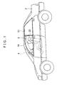
- a driving support device 1 is a device in which an image corresponding to a blind spot region of a vehicle is captured by a camera set on a vehicle outer wall and displayed to a driver in the vehicle, and in the present embodiment, a blind spot region generated by a front pillar of the vehicle is particularly targeted as the blind spot region of the vehicle. Further, as a method of displaying the image corresponding to the blind spot region, the one of projecting the image on the inside (i.e. interior side of the vehicle) of the front pillar by a projector is particularly applied in the present embodiment.
- FIG. 1 is an exterior view of a vehicle 2 mounting thereon the driving support device 1 according to the present embodiment
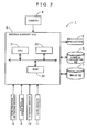
- FIG. 2 is a block diagram schematically showing a control system of the driving support device 1 according to the present embodiment.
- the driving support device 1 has a driving support ECU (a traveling state obtaining unit, an image extracting unit, an image outputting unit, a position predicting unit, and a blind spot region calculating unit) 3, a camera (imaging unit) 4, a projector 5, a camera parameter DB 6, an image DB 7, a head position detecting sensor 8, a vehicle speed sensor 9, a steering sensor 10, and a gyro sensor 11 set to the vehicle 2.
- a driving support ECU a traveling state obtaining unit, an image extracting unit, an image outputting unit, a position predicting unit, and a blind spot region calculating unit
- a camera (imaging unit) 4 a projector 5
- a camera parameter DB 6 an image DB 7
- a head position detecting sensor 8 a vehicle speed sensor 9, a steering sensor 10
- a gyro sensor 11 set to the vehicle 2.
- the driving support ECU (electronic control unit) 3 is an electronic control unit which extracts an image corresponding especially to a blind spot region generated by a right front pillar 12 from a captured image captured by the camera 4, and projects the extracted image on the inside of the right front pillar 12 using the projector 5, to thereby perform an image projection processing (refer to FIG. 6 ) and the like.
- the driving support ECU 3 may also serve as an ECU used for controlling a navigation device. A specific structure of the driving support ECU 3 will be described later.
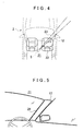
- the camera 4 is one in which a fixed imaging element such as a CCD, for instance, is used, and is attached to the outside of the right front pillar 12 of the vehicle 2 with its optical axis direction L set to be directed downward by a predetermined angle with respect to a horizontal direction. Further, as shown in FIG. 3 , the optical axis direction L of the camera 4 is directed in a right forward direction of the vehicle 2, and within a predetermined range around the optical axis direction L as a center is set as a captured region 15 in which an image of peripheral environments can be captured by the camera 4. The camera 4 captures an image in the right forward direction of the vehicle 2 when the vehicle 2 travels or stops, and the captured image that was captured (refer to FIG.
- a fixed imaging element such as a CCD, for instance
- the optical axis direction L is set to be the same direction as a visual recognition direction of the right front pillar 12 seen from a driver 16 (namely, a direction of the blind spot region generated by the right front pillar 12 seen from the driver 16).
- the projector 5 is a so-called liquid crystal projector formed of a liquid crystal panel and a light source used for projection.
- the projector 5 projects the image in which the blind spot region generated by the right front pillar 12 is captured on the inside of the right front pillar 12.
- FIG. 4 is a schematic view showing a projecting structure of the projector 5
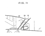
- FIG. 5 is a front view showing the inside of the right front pillar 12.
- the projector 5 is set inside of a roof 21 and in the vicinity of above in the vertical direction of a front seat 22 to be seated by the driver 16. Further, as shown in FIG. 5 , a screen 24 cut in accordance with the shape of the pillar adheres to the inside surface of the right front pillar 12. Furthermore, a focal point of the projector 5 is adjusted to the screen 24 such that a projection range of the projector 5 is set to match with a projection plane to be projected of the screen 24. As will be described later, by projecting the image using the projector 5, an image which is seen through the right front pillar 12 is displayed on the right front pillar 12 generating the blind spot region of the vehicle 2 (refer to FIG. 11 ).
- a DLP projector and an LCOS projector may be applied as the projector 5.
- the screen 24 may be omitted.
- the camera parameter DB 6 is a storage unit storing various parameters regarding the camera 4.
- the camera parameter DB 6 stores information regarding a setting position, a setting angle, an imaging range, a shooting plane of camera (refer to FIG. 7 ) and the like of the camera 4 with respect to the vehicle 2.
- the driving support ECU 3 extracts the image corresponding to the blind spot region generated by the right front pillar 12 from the captured image captured by the camera 4 using the various parameters stored in the camera parameter DB 6.
- the image DB 7 is a storage unit storing the captured image captured by the camera 4.
- the driving support ECU 3 performs a predetermined image processing on the captured image stored in the image DB 7, to thereby produce projection data to be projected by the projector 5.
- the head position detecting sensor 8 is formed of a plurality of ultrasonic sensors, and attached in the periphery of the driver 16 seated in the front seat 22 in the interior of the vehicle 2 at a position substantially the same height as the head part of the driver 16 or at a slightly higher position thereof.
- the driving support ECU 3 measures a period of time from when the ultrasonic wave is transmitted to when a reflected wave is received, to thereby detect the position of the head part. Subsequently, in the present embodiment, the driving support ECU 3 calculates the blind spot region of the vehicle based on a detection result from the head position detecting sensor 8.
- the vehicle speed sensor 9 being a sensor for detecting a moving distance and a vehicle speed of the vehicle generates pulses in accordance with a rotation of wheels of the vehicle 2, and outputs pulse signals to the driving support ECU 3. Subsequently, by counting the number of generated pulses, the driving support ECU 3 calculates a rotation speed of the wheels and the moving distance.
- the steering sensor 10 is a sensor attached to the inside of a steering device and capable of detecting a pivot angle of the steering.
- the gyro sensor 11 is a sensor capable detecting a turn angle of the vehicle 2. Further, by integrating the turn angle detected by the gyro sensor 11, it is possible to detect a vehicle direction.
- the driving support ECU 3 is formed of a CPU 31 as a core, in which a ROM 32 and a RAM 33 being storage units are connected to the CPU 31.
- the ROM 32 stores a later-described image projection processing program (refer to FIG. 6 ), and other than that, various programs and the like needed for controlling the camera 4, the projector 5 and the like.
- the RAM 33 is a memory temporarily storing various data operated in the CPU 31.
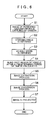
- FIG. 6 is a flow chart of the image projection processing program according to the present embodiment.
- the image projection processing program is repeatedly executed at every predetermined period of time (every 200 ms, for instance) after an ignition of the vehicle 2 is turned on or after a predetermined operation is performed by a user with an operation panel (not shown), and performs processing to extract the image corresponding especially to the blind spot region generated by the right front pillar 12 from the captured image captured by the camera 4 when the vehicle 2 travels or stops, and to project the extracted image on the inside of the right front pillar 12 using the projector 5.
- programs to be described below shown by the flow chart in FIG. 6 are stored in the ROM 32 and the RAM 33 included in the driving support ECU 3, and are executed by the CPU 31.
- step (hereinafter, abbreviated as S) 1 the CPU 31 first captures an image of peripheral environments in a right forward direction in a traveling direction of a vehicle using the camera 4, to thereby obtain a captured image. Subsequently, the obtained captured image is temporality stored in the image DB 7.
- the CPU 31 obtains a steering angle of the vehicle based on the detection result from the steering sensor 10. Further, in S3, the CPU 31 obtains a vehicle speed of the vehicle based on the detection result from the vehicle speed sensor 9. Note that the aforementioned S2 and S3 correspond to processes conducted by the traveling state obtaining unit.
- the CPU 31 predicts a vehicle position after a predetermined period of time using the traveling state of the vehicle obtained in the aforementioned S2 and S3, and further calculates a blind spot region of the vehicle located at the predicted position.
- the predetermined period of time is a required period of time from the capturing of the image of the peripheral environments using the camera 4 to the output of the captured image using the projector 5 (namely, the display of the captured image on the screen 24), and a value thereof is determined depending on the performance of the camera 4 and the CPU 31. For instance, the value is set at 100 ms in the present embodiment.
- FIG. 7 shows a case where the vehicle 2 goes straight
- FIG. 8 shows a case where the vehicle 2 turns right
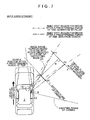
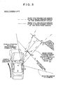
- FIG. 9 shows a case where the vehicle 2 turns left.
- the CPU 31 detects the head position of the driver 16 using the head position detecting sensor 8.
- the CPU 31 predicts the vehicle position after the predetermined period of time based on the traveling state of the vehicle obtained in the aforementioned S2 and S3.
- the CPU 31 predicts the head position of the driver 16 after the predetermined period of time. Subsequently, based on the prediction result of the head position of the driver 16 after the predetermined period of time and the position and the shape of the right front pillar 12 with respect to the head position of the driver 16, the CPU 31 calculates the blind spot region for the driver 16 after the predetermined period of time generated by the right front pillar 12. Note that as shown in FIG. 7 to FIG.
- the blind spot region for the driver 16 generated by the right front pillar 12 at the position after the predetermined period of time (namely, at a point where the captured image is displayed) from when the vehicle exists at the current position (namely, at a spot where the captured image was captured) becomes respectively different regions depending on a traveling trace of the vehicle.
- the aforementioned S4 corresponds to processes conducted by the position predicting unit and the blind spot region calculating unit.
- FIG. 10 is a view showing a captured image 50 captured by the camera 4.
- the CPU 31 sets a virtual plane X after the predetermined period of time based on the blind spot region for the driver 16 after the predetermined period of time generated by the right front pillar 12 calculated in the aforementioned S4, as shown in FIG. 7 to FIG. 9 .
- the virtual plane X is a plane for correcting a mismatch between the visibility of the camera 4 and the visibility of the driver 16, and is a virtual surface set in accordance with the visibility of the driver in which the visibility of the driver 16 is determined as the origin.
- the virtual plane X is orthogonal to a line H joining a predicted head position of the driver 16 and a center of the right front pillar 12, and is set at a position with a predetermined distance (10 m, for instance) apart from the vehicle 2.
- the CPU 31 obtains a shooting plane of camera Y.
- the shooting plane of camera Y is previously determined based on a design value (a resolution, a setting angle with respect to a vehicle body, and so on) and the like of the camera 4, and is stored in the camera parameter DB 6. Further, the camera 4 focuses on the shooting plane of camera Y to capture the image in the aforementioned S1.
- the CPU 31 calculates overlap regions P1 to P2 between the blind spot region for the driver 16 after the predetermined period of time calculated in the aforementioned S4 and the virtual plane X. Further, the CPU 31 calculates a visibility region in which the calculated overlap regions P1 to P2 match with the visibility of the camera 4 (namely, the blind spot region for the driver after the predetermined period of time seen through the camera), and specifies regions Q1 to Q2 in which the calculated visibility region and the shooting plane of camera Y overlap as an image range 51 corresponding to the blind spot region of the vehicle 2 after the predetermined period of time (point in time when displaying the captured image). Subsequently, an image in the specified image range 51 is extracted from the captured image 50, as shown in FIG. 10 .
- an image range 52 corresponding to a blind spot region of the vehicle 2 at the current (namely, at a point in time when capturing the image with the camera) position is also shown in FIG. 10 .
- the image range to be extracted is a region different from the blind spot region of the vehicle 2 at the current position, so that it is possible to accurately extract the actual blind spot region of the vehicle at the point in time when outputting the image.
- the aforementioned S4 and S5 correspond to processes conducted by the image extracting unit.
- the CPU 31 performs a projection conversion of the image extracted in the aforementioned S5 to project it on the virtual plane, thereby generating projection data.
- the CPU 31 performs the projection conversion of the image extracted in the aforementioned S5 to project it on the virtual plane X.
- the projection conversion is a process for performing a coordinate transformation in which coordinates of each pixel of the image existing in the image range 51 among the shooting plane of camera Y are transformed to those of each pixel of the virtual plane X, and is conducted by using a publicly known coordinate transformation.
- the image being projection-converted on the virtual plane X is converted in accordance with the shape of the right front pillar 12 stored in the ROM 32, and the converted image is further coordinate-transformed in accordance with the position of the projector 5 so as to be projected by the projector 5.
- the image to be displayed on the inside surface of the right front pillar 12 is distorted, enlarged or reduced depending on an angle by which the light output from the projector 5 is incident to the inside surface of the pillar.
- a map or the like in which the coordinates of the respective pixels of the projection-converted image and the coordinates of the respective pixels of the image to be output to the projector 5 are previously correlated with each other is previously stored in a memory or the like, and based on the map, the projection-converted image is further coordinate-transformed to be an output image to the projector 5. Subsequently, the coordinate-transformed image is set as projection data to be output to the projector 5.
- the CPU 31 outputs the generated projection data using the projector 5, thereby projecting the image of the region being blocked by the pillar on the screen 24 set on the inside surface of the right front pillar 12.
- the projected image displayed on the screen 24 is projection-converted on the virtual plane X, so that the projected image is displayed without being deviated or inclined from a background visually recognized through a front window or a door window, as shown in FIG. 11 . Therefore, even when an object such as a person and an approaching vehicle exists in a position hidden by the right front pillar 12, the driver 16 of the vehicle 2 can easily grasp the existence.
- the image seen through the right front pillar 12 generating the blind spot is formed with more realistic formation, which enables the driver to more accurately grasp the state of the object located in the blind spot.
- the aforementioned S7 corresponds to processes conducted by the image outputting unit.
- the driving support device 1 the driving support method conducted by the driving support device 1, and the computer program executed in the driving support device 1 according to the present embodiment
- the image of the peripheral environments of the vehicle 2 is captured by the camera 4 (S1)
- the traveling state of the vehicle 2 is obtained (S2 and S3)
- the blind spot region seen from the driver generated by the right front pillar 12 after the predetermined period of time is calculated by considering the time lag until the captured image captured by the camera 4 is projected by the projector 5 (S4)
- the image corresponding to the calculated blind spot region is extracted from the captured image captured by the camera 4 (S5)
- the extracted image is projected on the inside surface of the right front pillar 12 using the projector 5 (S7), so that even when the time lag is generated between the point in time when capturing the image and the point in time when displaying the captured image, it becomes possible to accurately display the actual blind spot region of the vehicle.
- the actual peripheral circumstances of the vehicle 2 and the peripheral circumstances of the vehicle displayed on the inside surface of the right front pillar 12 are not different to each other, which enables the driver to make appropriate judgments. Further, since the position of the vehicle 2 after the predetermined period of time is predicted, and the blind spot region from the position is calculated, it becomes possible to appropriately extract the image in which the peripheral circumstances of the vehicle 2 after the predetermined period of time is captured, from the captured image. Furthermore, since the image corresponding to the blind spot region generated by the right front pillar 12 of the vehicle 2 is displayed on the inside of the right front pillar 12, a driving environment is improved without reducing the visibility of the driver.
- the present embodiment is structured such that the image corresponding to the blind spot region generated by the right front pillar 12 is projected on the inside surface of the right front pillar 12 using the projector 5 to thereby compensate the visibility in the blind spot seen from the vehicle, but, it may be structured such that the image corresponding to the blind spot region is displayed on a display set on the inside surface of the pillar in the vehicle to thereby compensate the visibility in the blind spot seen from the vehicle.
- the image projection processing program ( FIG. 6 ) may be executed only when the vehicle 2 approaches within a predetermined distance of an intersection or a curve. At this time, it is preferable to determine whether the vehicle 2 approaches within the predetermined distance of the intersection or the curve by performing a map matching process with the navigation device. Further, the image projection processing program may be executed under the situation where the recognition of the peripheral environments becomes important such as an entrance/exit of a parking lot and a merging road in an expressway, in addition to the intersection and the curve.
- the blind spot region generated by the right front pillar 12 at a side of the driver is displayed on the inside surface of the right front pillar 12, but, it is possible to display a blind spot region generated by a left front pillar at a side of a front passenger's seat.
- it is structured such that the camera is set on the left front pillar, and an image extracted from a captured image range is displayed on the inside surface of the left front pillar.
Landscapes
- Engineering & Computer Science (AREA)
- Multimedia (AREA)
- Mechanical Engineering (AREA)
- Closed-Circuit Television Systems (AREA)
- Fittings On The Vehicle Exterior For Carrying Loads, And Devices For Holding Or Mounting Articles (AREA)
- Traffic Control Systems (AREA)
Applications Claiming Priority (1)
| Application Number | Priority Date | Filing Date | Title |
|---|---|---|---|
| JP2007258641A JP4412380B2 (ja) | 2007-10-02 | 2007-10-02 | 運転支援装置、運転支援方法及びコンピュータプログラム |
Publications (3)
| Publication Number | Publication Date |
|---|---|
| EP2045132A2 true EP2045132A2 (fr) | 2009-04-08 |
| EP2045132A3 EP2045132A3 (fr) | 2010-06-02 |
| EP2045132B1 EP2045132B1 (fr) | 2012-06-20 |
Family
ID=40091861
Family Applications (1)
| Application Number | Title | Priority Date | Filing Date |
|---|---|---|---|
| EP08016123A Not-in-force EP2045132B1 (fr) | 2007-10-02 | 2008-09-12 | Dispositif de support de commande, procédé de support de commande, et programme informatique |
Country Status (4)
| Country | Link |
|---|---|
| US (1) | US8089512B2 (fr) |
| EP (1) | EP2045132B1 (fr) |
| JP (1) | JP4412380B2 (fr) |
| CN (1) | CN101404122B (fr) |
Cited By (4)
| Publication number | Priority date | Publication date | Assignee | Title |
|---|---|---|---|---|
| WO2015013311A1 (fr) * | 2013-07-22 | 2015-01-29 | Johnson Controls Technology Company | Système d'imagerie de véhicule |
| WO2015015928A1 (fr) * | 2013-07-30 | 2015-02-05 | Toyota Jidosha Kabushiki Kaisha | Dispositif d'assistance à la conduite |
| WO2016018320A1 (fr) * | 2014-07-30 | 2016-02-04 | Johnson Controls Technology Company | Système de projection d'une image à l'intérieur d'un habitacle de véhicule |
| EP3683095A1 (fr) * | 2014-04-09 | 2020-07-22 | Jaguar Land Rover Limited | Appareil et procédé d'affichage d'informations |
Families Citing this family (59)
| Publication number | Priority date | Publication date | Assignee | Title |
|---|---|---|---|---|
| US8547298B2 (en) * | 2009-04-02 | 2013-10-01 | GM Global Technology Operations LLC | Continuation of exterior view on interior pillars and surfaces |
| US8502860B2 (en) * | 2009-09-29 | 2013-08-06 | Toyota Motor Engineering & Manufacturing North America (Tema) | Electronic control system, electronic control unit and associated methodology of adapting 3D panoramic views of vehicle surroundings by predicting driver intent |
| DE102010015079A1 (de) * | 2010-04-15 | 2011-10-20 | Valeo Schalter Und Sensoren Gmbh | Verfahren zum Anzeigen eines Bildes auf einer Anzeigeeinrichtung in einem Fahrzeug. Fahrerassistenzsystem und Fahrzeug |
| DE102010034853A1 (de) * | 2010-08-18 | 2012-02-23 | Gm Global Technology Operations Llc (N.D.Ges.D. Staates Delaware) | Kraftfahrzeug mit Digitalprojektoren |
| US8733938B2 (en) | 2012-03-07 | 2014-05-27 | GM Global Technology Operations LLC | Virtual convertible tops, sunroofs, and back windows, and systems and methods for providing same |
| BR112016006666B1 (pt) * | 2013-09-27 | 2023-04-04 | Nissan Motor Co., Ltd | Sistema de apresentação de informações |
| JP6176039B2 (ja) * | 2013-10-02 | 2017-08-09 | トヨタ自動車株式会社 | 運転支援装置 |
| JP6032219B2 (ja) * | 2014-01-24 | 2016-11-24 | トヨタ自動車株式会社 | 運転支援装置 |
| JP2015154337A (ja) * | 2014-02-17 | 2015-08-24 | 株式会社デンソー | 対象範囲設定装置、および対象範囲設定プログラム |
| JP5920380B2 (ja) * | 2014-02-26 | 2016-05-18 | トヨタ自動車株式会社 | 画像投影装置及び運転支援装置 |
| CN103818320B (zh) * | 2014-03-14 | 2016-03-02 | 盛凯 | 驾驶舱用智能控制系统及控制方法 |
| GB2525653A (en) * | 2014-05-01 | 2015-11-04 | Jaguar Land Rover Ltd | Apparatus and method for providing information within a vehicle |
| KR101596751B1 (ko) * | 2014-09-26 | 2016-02-23 | 현대자동차주식회사 | 운전자 맞춤형 사각 영역 표시 방법 및 장치 |
| CN107615757B (zh) * | 2015-05-29 | 2018-10-09 | 日产自动车株式会社 | 信息呈现系统 |
| WO2017024458A1 (fr) * | 2015-08-10 | 2017-02-16 | Bayerische Motoren Werke Aktiengesellschaft | Système, procédé et appareil pour véhicule et support lisible par ordinateur |
| CA2901477C (fr) | 2015-08-25 | 2023-07-18 | Evolution Optiks Limited | Systeme de correction de la vision, methode et interface utilisateur graphique destinee a la mise en place de dispositifs electroniques ayant un afficheur graphique |
| US9902322B2 (en) | 2015-10-30 | 2018-02-27 | Bendix Commercial Vehicle Systems Llc | Filling in surround view areas blocked by mirrors or other vehicle parts |
| WO2017077652A1 (fr) * | 2015-11-06 | 2017-05-11 | 株式会社島津製作所 | Appareil à rayons x mobile |
| US9727793B2 (en) * | 2015-12-15 | 2017-08-08 | Honda Motor Co., Ltd. | System and method for image based vehicle localization |
| JP6428665B2 (ja) * | 2016-02-10 | 2018-11-28 | 三菱電機株式会社 | 空中映像表示装置 |
| JP6728868B2 (ja) * | 2016-03-28 | 2020-07-22 | 大日本印刷株式会社 | 表示装置、表示方法及び表示装置用プログラム |
| DE102016214046A1 (de) * | 2016-07-29 | 2018-02-01 | Bayerische Motoren Werke Aktiengesellschaft | Verfahren zum Betreiben eines Fahrerassistenzsystems mit einer Datenbrille sowie ein Anzeigesystem mit einer Datenbrille |
| DE102016214316A1 (de) * | 2016-08-03 | 2018-02-08 | Bayerische Motoren Werke Aktiengesellschaft | Verfahren und Vorrichtung zum Erkennen eines durch ein Fahrzeugteil zumindest teilverdeckten Objekts in einer Fahrzeugumgebung eines Kraftfahrzeugs |
| DE102016224510A1 (de) * | 2016-12-08 | 2018-06-14 | Audi Ag | Verfahren zur Bereitstellung von Ergebnisdaten, die von einem Kraftfahrzeugumfeld abhängen |
| WO2018129310A1 (fr) * | 2017-01-08 | 2018-07-12 | Shanghai Yanfeng Jinqiao Automotive Trim Systems Co. Ltd | Système et procédé d'affichage d'image sur un élément intérieur de véhicule |
| DE102017205630A1 (de) * | 2017-04-03 | 2018-10-04 | Conti Temic Microelectronic Gmbh | Kameravorrichtung und Verfahren zur Erfassung eines Umgebungsbereichs eines Fahrzeugs |
| KR102347689B1 (ko) * | 2017-04-10 | 2022-01-05 | 현대자동차주식회사 | 차량의 사각존용 필러 디스플레이 장치 |
| US10033978B1 (en) | 2017-05-08 | 2018-07-24 | International Business Machines Corporation | Projecting obstructed content over touch screen obstructions |
| CN107264405A (zh) * | 2017-06-26 | 2017-10-20 | 上汽依维柯红岩商用车有限公司 | 用于消除盲区的车载系统及其控制方法 |
| JP2019014450A (ja) * | 2017-07-10 | 2019-01-31 | トヨタ自動車株式会社 | 車両用表示装置 |
| JP2019073091A (ja) * | 2017-10-13 | 2019-05-16 | トヨタ自動車株式会社 | 車両用表示装置 |
| KR102022980B1 (ko) * | 2017-12-01 | 2019-09-19 | 클릭트 주식회사 | 깊이데이터를 이용한 증강현실영상 제공방법 및 프로그램 |
| DE112018006931T5 (de) * | 2018-02-27 | 2020-10-08 | Mitsubishi Electric Corporation | Fahrzeugbildschirmsteuerungssystem und bildschirmsteuerungsverfahren |
| US11693239B2 (en) | 2018-03-09 | 2023-07-04 | Evolution Optiks Limited | Vision correction system and method, light field display and light field shaping layer and alignment therefor |
| US11353699B2 (en) | 2018-03-09 | 2022-06-07 | Evolution Optiks Limited | Vision correction system and method, light field display and light field shaping layer and alignment therefor |
| CA3021636A1 (fr) | 2018-10-22 | 2020-04-22 | Evolution Optiks Limited | Afficheur de champ lumineux, procede de rendu de pixels adapte connexe, et systeme et procede de correction de la vision |
| US11244080B2 (en) | 2018-10-09 | 2022-02-08 | International Business Machines Corporation | Project content from flexible display touch device to eliminate obstruction created by finger |
| US10761604B2 (en) | 2018-10-22 | 2020-09-01 | Evolution Optiks Limited | Light field vision testing device, adjusted pixel rendering method therefor, and vision testing system and method using same |
| US11500460B2 (en) | 2018-10-22 | 2022-11-15 | Evolution Optiks Limited | Light field device, optical aberration compensation or simulation rendering |
| US10636116B1 (en) | 2018-10-22 | 2020-04-28 | Evolution Optiks Limited | Light field display, adjusted pixel rendering method therefor, and vision correction system and method using same |
| US10860099B2 (en) | 2018-10-22 | 2020-12-08 | Evolution Optiks Limited | Light field display, adjusted pixel rendering method therefor, and adjusted vision perception system and method using same addressing astigmatism or similar conditions |
| US11327563B2 (en) | 2018-10-22 | 2022-05-10 | Evolution Optiks Limited | Light field vision-based testing device, adjusted pixel rendering method therefor, and online vision-based testing management system and method using same |
| US11966507B2 (en) | 2018-10-22 | 2024-04-23 | Evolution Optiks Limited | Light field vision testing device, adjusted pixel rendering method therefor, and vision testing system and method using same |
| US10936064B2 (en) | 2018-10-22 | 2021-03-02 | Evolution Optiks Limited | Light field display, adjusted pixel rendering method therefor, and adjusted vision perception system and method using same addressing astigmatism or similar conditions |
| US11500461B2 (en) | 2019-11-01 | 2022-11-15 | Evolution Optiks Limited | Light field vision-based testing device, system and method |
| WO2020219446A1 (fr) | 2019-04-23 | 2020-10-29 | Evolution Optiks Limited | Dispositif d'affichage numérique comprenant une partie d'affichage ou d'affichage de champ lumineux complémentaire, et système de correction de la vision et procédé l'utilisant |
| WO2020219711A1 (fr) | 2019-04-23 | 2020-10-29 | Evolution Optiks Limited | Affichage de champ lumineux et couche de mise en forme de champ lumineux vibrante, et dispositif de test et/ou de correction de la vision |
| WO2021038422A2 (fr) | 2019-08-26 | 2021-03-04 | Evolution Optiks Limited | Dispositif d'affichage de champ lumineux binoculaire, procédé de rendu de pixels ajusté associé, et système de correction de vision et procédé l'utilisant |
| US11823598B2 (en) | 2019-11-01 | 2023-11-21 | Evolution Optiks Limited | Light field device, variable perception pixel rendering method therefor, and variable perception system and method using same |
| US12112665B2 (en) | 2019-11-01 | 2024-10-08 | Evolution Optiks Limited | Light field device, variable perception pixel rendering method therefor, and variable perception system and method using same |
| US11487361B1 (en) | 2019-11-01 | 2022-11-01 | Evolution Optiks Limited | Light field device and vision testing system using same |
| US12360592B2 (en) | 2019-11-01 | 2025-07-15 | Evolution Optiks Limited | Light field device and vision testing system using same |
| CN110901534A (zh) * | 2019-11-14 | 2020-03-24 | 浙江合众新能源汽车有限公司 | 一种a柱透视实现方法及系统 |
| CN111391755B (zh) * | 2020-03-10 | 2021-10-12 | 京东方科技集团股份有限公司 | 盲区图像的显示方法、装置及系统 |
| CN111522443B (zh) * | 2020-04-13 | 2024-04-05 | 京东方科技集团股份有限公司 | 车辆a柱显示组件的显示方法、系统、设备和存储介质 |
| CN112172798B (zh) * | 2020-09-28 | 2022-02-01 | 惠州华阳通用电子有限公司 | 一种基于积水环境的泊车方法及存储介质 |
| CN112356826B (zh) * | 2020-10-28 | 2022-02-01 | 惠州华阳通用电子有限公司 | 一种辅助泊车方法及存储介质 |
| CN114268787B (zh) * | 2021-12-20 | 2024-06-11 | 东软集团股份有限公司 | 基于ar-hud的延时补偿方法、装置、设备及存储介质 |
| CN116533881A (zh) * | 2023-04-27 | 2023-08-04 | 岚图汽车科技有限公司 | 车辆的视野扩展方法及相关设备 |
Citations (6)
| Publication number | Priority date | Publication date | Assignee | Title |
|---|---|---|---|---|
| US20030108222A1 (en) | 2001-12-12 | 2003-06-12 | Kabushikikaisha Equos Research | Image processing system for vehicle |
| US20030151563A1 (en) | 2002-02-08 | 2003-08-14 | Kulas Charles J. | Reduction of blind spots by using display screens |
| JP2005184225A (ja) | 2003-12-17 | 2005-07-07 | Denso Corp | 車両用表示装置 |
| US20050168695A1 (en) | 2004-01-16 | 2005-08-04 | Kabushiki Kaisha Honda Lock | Vehicular visual assistance system |
| WO2006027563A1 (fr) | 2004-09-06 | 2006-03-16 | Mch Technology Limited | Systeme d'amelioration de la visibilite destine a un vehicule |
| JP2006290304A (ja) | 2005-04-14 | 2006-10-26 | Aisin Aw Co Ltd | 車両外部表示方法及び表示装置 |
Family Cites Families (10)
| Publication number | Priority date | Publication date | Assignee | Title |
|---|---|---|---|---|
| EP1179958B1 (fr) * | 1999-04-16 | 2012-08-08 | Panasonic Corporation | Dispositif de traitement d'images et systeme de surveillance |
| EP1167120B1 (fr) * | 2000-06-30 | 2014-08-27 | Panasonic Corporation | Dispositif de rendu pour faciliter le stationnement d'un véhicule |
| JP2004312638A (ja) * | 2003-04-10 | 2004-11-04 | Mitsubishi Electric Corp | 障害物検知装置 |
| JP4583883B2 (ja) | 2004-11-08 | 2010-11-17 | パナソニック株式会社 | 車両用周囲状況表示装置 |
| JP2006303583A (ja) | 2005-04-15 | 2006-11-02 | Aisin Aw Co Ltd | 車体外部表示装置及び車両外部表示装置の初期化方法 |
| JP2006311272A (ja) * | 2005-04-28 | 2006-11-09 | Denso Corp | 車両用映像表示装置 |
| US8179435B2 (en) * | 2005-09-28 | 2012-05-15 | Nissan Motor Co., Ltd. | Vehicle surroundings image providing system and method |
| JP4497133B2 (ja) * | 2006-07-12 | 2010-07-07 | アイシン・エィ・ダブリュ株式会社 | 運転支援方法及び運転支援装置 |
| US9126533B2 (en) * | 2007-02-23 | 2015-09-08 | Aisin Aw Co., Ltd. | Driving support method and driving support device |
| JP4748082B2 (ja) * | 2007-02-23 | 2011-08-17 | トヨタ自動車株式会社 | 車両用周辺監視装置及び車両用周辺監視方法 |
-
2007
- 2007-10-02 JP JP2007258641A patent/JP4412380B2/ja not_active Expired - Fee Related
-
2008
- 2008-08-14 CN CN200810145966.9A patent/CN101404122B/zh not_active Expired - Fee Related
- 2008-09-12 EP EP08016123A patent/EP2045132B1/fr not_active Not-in-force
- 2008-09-17 US US12/232,414 patent/US8089512B2/en not_active Expired - Fee Related
Patent Citations (6)
| Publication number | Priority date | Publication date | Assignee | Title |
|---|---|---|---|---|
| US20030108222A1 (en) | 2001-12-12 | 2003-06-12 | Kabushikikaisha Equos Research | Image processing system for vehicle |
| US20030151563A1 (en) | 2002-02-08 | 2003-08-14 | Kulas Charles J. | Reduction of blind spots by using display screens |
| JP2005184225A (ja) | 2003-12-17 | 2005-07-07 | Denso Corp | 車両用表示装置 |
| US20050168695A1 (en) | 2004-01-16 | 2005-08-04 | Kabushiki Kaisha Honda Lock | Vehicular visual assistance system |
| WO2006027563A1 (fr) | 2004-09-06 | 2006-03-16 | Mch Technology Limited | Systeme d'amelioration de la visibilite destine a un vehicule |
| JP2006290304A (ja) | 2005-04-14 | 2006-10-26 | Aisin Aw Co Ltd | 車両外部表示方法及び表示装置 |
Cited By (7)
| Publication number | Priority date | Publication date | Assignee | Title |
|---|---|---|---|---|
| WO2015013311A1 (fr) * | 2013-07-22 | 2015-01-29 | Johnson Controls Technology Company | Système d'imagerie de véhicule |
| WO2015015928A1 (fr) * | 2013-07-30 | 2015-02-05 | Toyota Jidosha Kabushiki Kaisha | Dispositif d'assistance à la conduite |
| CN105209299A (zh) * | 2013-07-30 | 2015-12-30 | 丰田自动车株式会社 | 驾驶辅助装置 |
| CN105209299B (zh) * | 2013-07-30 | 2017-09-15 | 丰田自动车株式会社 | 驾驶辅助装置 |
| EP3683095A1 (fr) * | 2014-04-09 | 2020-07-22 | Jaguar Land Rover Limited | Appareil et procédé d'affichage d'informations |
| US11597318B2 (en) | 2014-04-09 | 2023-03-07 | Jaguar Land Rover Limited | Apparatus and method for displaying information |
| WO2016018320A1 (fr) * | 2014-07-30 | 2016-02-04 | Johnson Controls Technology Company | Système de projection d'une image à l'intérieur d'un habitacle de véhicule |
Also Published As
| Publication number | Publication date |
|---|---|
| US8089512B2 (en) | 2012-01-03 |
| US20090086019A1 (en) | 2009-04-02 |
| CN101404122B (zh) | 2013-01-02 |
| EP2045132B1 (fr) | 2012-06-20 |
| JP2009083764A (ja) | 2009-04-23 |
| JP4412380B2 (ja) | 2010-02-10 |
| CN101404122A (zh) | 2009-04-08 |
| EP2045132A3 (fr) | 2010-06-02 |
Similar Documents
| Publication | Publication Date | Title |
|---|---|---|
| EP2045132B1 (fr) | Dispositif de support de commande, procédé de support de commande, et programme informatique | |
| EP1974998B1 (fr) | Procédé d'assistance à la conduite et appareil d'assistance à la conduite | |
| JP4530060B2 (ja) | 駐車支援装置及び方法 | |
| JP4862774B2 (ja) | 運転支援方法及び運転支援装置 | |
| US9126533B2 (en) | Driving support method and driving support device | |
| RU2734643C1 (ru) | Способ помощи при парковке для устройства помощи при парковке и устройство помощи при парковке | |
| US8305204B2 (en) | Vehicle surrounding confirmation apparatus | |
| US8044781B2 (en) | System and method for displaying a 3D vehicle surrounding with adjustable point of view including a distance sensor | |
| US9418556B2 (en) | Apparatus and method for displaying a blind spot | |
| US8330816B2 (en) | Image processing device | |
| US20160207526A1 (en) | Vehicle-side method and vehicle-side device for detecting and displaying parking spaces for a vehicle | |
| US20150042799A1 (en) | Object highlighting and sensing in vehicle image display systems | |
| JP5471141B2 (ja) | 駐車支援装置及び駐車支援方法 | |
| CN102632840B (zh) | 车辆周围监测装置 | |
| JP2008265719A (ja) | 運転支援方法及び運転支援装置 | |
| JP2006298115A (ja) | 運転支援方法及び運転支援装置 | |
| JP4784572B2 (ja) | 運転支援方法及び運転支援装置 | |
| JP2008222153A (ja) | 合流支援装置 | |
| JP2009211624A (ja) | 運転支援装置、運転支援方法及びコンピュータプログラム | |
| JP2012176656A (ja) | 駐車支援装置 | |
| JP2016175549A (ja) | 安全確認支援装置、安全確認支援方法 | |
| EP1803602A1 (fr) | Procédé et appareil d'assistance à la conduite | |
| EP2757781B1 (fr) | Dispositif de vérification de l'axe optique d'une caméra embarquée à bord d'un véhicule | |
| KR102164702B1 (ko) | 자동 주차 장치 및 자동 주차 방법 | |
| CN114103812B (zh) | 倒车入库引导系统及方法 |
Legal Events
| Date | Code | Title | Description |
|---|---|---|---|
| PUAI | Public reference made under article 153(3) epc to a published international application that has entered the european phase |
Free format text: ORIGINAL CODE: 0009012 |
|
| AK | Designated contracting states |
Kind code of ref document: A2 Designated state(s): AT BE BG CH CY CZ DE DK EE ES FI FR GB GR HR HU IE IS IT LI LT LU LV MC MT NL NO PL PT RO SE SI SK TR |
|
| AX | Request for extension of the european patent |
Extension state: AL BA MK RS |
|
| PUAL | Search report despatched |
Free format text: ORIGINAL CODE: 0009013 |
|
| AK | Designated contracting states |
Kind code of ref document: A3 Designated state(s): AT BE BG CH CY CZ DE DK EE ES FI FR GB GR HR HU IE IS IT LI LT LU LV MC MT NL NO PL PT RO SE SI SK TR |
|
| AX | Request for extension of the european patent |
Extension state: AL BA MK RS |
|
| 17P | Request for examination filed |
Effective date: 20101123 |
|
| AKX | Designation fees paid |
Designated state(s): AT BE BG CH CY CZ DE DK EE ES FI FR GB GR HR HU IE IS IT LI LT LU LV MC MT NL NO PL PT RO SE SI SK TR |
|
| GRAP | Despatch of communication of intention to grant a patent |
Free format text: ORIGINAL CODE: EPIDOSNIGR1 |
|
| GRAS | Grant fee paid |
Free format text: ORIGINAL CODE: EPIDOSNIGR3 |
|
| GRAA | (expected) grant |
Free format text: ORIGINAL CODE: 0009210 |
|
| AK | Designated contracting states |
Kind code of ref document: B1 Designated state(s): AT BE BG CH CY CZ DE DK EE ES FI FR GB GR HR HU IE IS IT LI LT LU LV MC MT NL NO PL PT RO SE SI SK TR |
|
| REG | Reference to a national code |
Ref country code: GB Ref legal event code: FG4D |
|
| REG | Reference to a national code |
Ref country code: CH Ref legal event code: EP |
|
| REG | Reference to a national code |
Ref country code: AT Ref legal event code: REF Ref document number: 562857 Country of ref document: AT Kind code of ref document: T Effective date: 20120715 |
|
| REG | Reference to a national code |
Ref country code: IE Ref legal event code: FG4D |
|
| REG | Reference to a national code |
Ref country code: DE Ref legal event code: R096 Ref document number: 602008016364 Country of ref document: DE Effective date: 20120823 |
|
| PG25 | Lapsed in a contracting state [announced via postgrant information from national office to epo] |
Ref country code: LT Free format text: LAPSE BECAUSE OF FAILURE TO SUBMIT A TRANSLATION OF THE DESCRIPTION OR TO PAY THE FEE WITHIN THE PRESCRIBED TIME-LIMIT Effective date: 20120620 Ref country code: FI Free format text: LAPSE BECAUSE OF FAILURE TO SUBMIT A TRANSLATION OF THE DESCRIPTION OR TO PAY THE FEE WITHIN THE PRESCRIBED TIME-LIMIT Effective date: 20120620 Ref country code: SE Free format text: LAPSE BECAUSE OF FAILURE TO SUBMIT A TRANSLATION OF THE DESCRIPTION OR TO PAY THE FEE WITHIN THE PRESCRIBED TIME-LIMIT Effective date: 20120620 Ref country code: NO Free format text: LAPSE BECAUSE OF FAILURE TO SUBMIT A TRANSLATION OF THE DESCRIPTION OR TO PAY THE FEE WITHIN THE PRESCRIBED TIME-LIMIT Effective date: 20120920 |
|
| REG | Reference to a national code |
Ref country code: NL Ref legal event code: VDEP Effective date: 20120620 |
|
| REG | Reference to a national code |
Ref country code: AT Ref legal event code: MK05 Ref document number: 562857 Country of ref document: AT Kind code of ref document: T Effective date: 20120620 |
|
| REG | Reference to a national code |
Ref country code: LT Ref legal event code: MG4D Effective date: 20120620 |
|
| PG25 | Lapsed in a contracting state [announced via postgrant information from national office to epo] |
Ref country code: SI Free format text: LAPSE BECAUSE OF FAILURE TO SUBMIT A TRANSLATION OF THE DESCRIPTION OR TO PAY THE FEE WITHIN THE PRESCRIBED TIME-LIMIT Effective date: 20120620 Ref country code: LV Free format text: LAPSE BECAUSE OF FAILURE TO SUBMIT A TRANSLATION OF THE DESCRIPTION OR TO PAY THE FEE WITHIN THE PRESCRIBED TIME-LIMIT Effective date: 20120620 Ref country code: GR Free format text: LAPSE BECAUSE OF FAILURE TO SUBMIT A TRANSLATION OF THE DESCRIPTION OR TO PAY THE FEE WITHIN THE PRESCRIBED TIME-LIMIT Effective date: 20120921 Ref country code: HR Free format text: LAPSE BECAUSE OF FAILURE TO SUBMIT A TRANSLATION OF THE DESCRIPTION OR TO PAY THE FEE WITHIN THE PRESCRIBED TIME-LIMIT Effective date: 20120620 |
|
| PG25 | Lapsed in a contracting state [announced via postgrant information from national office to epo] |
Ref country code: AT Free format text: LAPSE BECAUSE OF FAILURE TO SUBMIT A TRANSLATION OF THE DESCRIPTION OR TO PAY THE FEE WITHIN THE PRESCRIBED TIME-LIMIT Effective date: 20120620 Ref country code: RO Free format text: LAPSE BECAUSE OF FAILURE TO SUBMIT A TRANSLATION OF THE DESCRIPTION OR TO PAY THE FEE WITHIN THE PRESCRIBED TIME-LIMIT Effective date: 20120620 Ref country code: CZ Free format text: LAPSE BECAUSE OF FAILURE TO SUBMIT A TRANSLATION OF THE DESCRIPTION OR TO PAY THE FEE WITHIN THE PRESCRIBED TIME-LIMIT Effective date: 20120620 Ref country code: CY Free format text: LAPSE BECAUSE OF FAILURE TO SUBMIT A TRANSLATION OF THE DESCRIPTION OR TO PAY THE FEE WITHIN THE PRESCRIBED TIME-LIMIT Effective date: 20120620 Ref country code: SK Free format text: LAPSE BECAUSE OF FAILURE TO SUBMIT A TRANSLATION OF THE DESCRIPTION OR TO PAY THE FEE WITHIN THE PRESCRIBED TIME-LIMIT Effective date: 20120620 Ref country code: IS Free format text: LAPSE BECAUSE OF FAILURE TO SUBMIT A TRANSLATION OF THE DESCRIPTION OR TO PAY THE FEE WITHIN THE PRESCRIBED TIME-LIMIT Effective date: 20121020 Ref country code: EE Free format text: LAPSE BECAUSE OF FAILURE TO SUBMIT A TRANSLATION OF THE DESCRIPTION OR TO PAY THE FEE WITHIN THE PRESCRIBED TIME-LIMIT Effective date: 20120620 Ref country code: BE Free format text: LAPSE BECAUSE OF FAILURE TO SUBMIT A TRANSLATION OF THE DESCRIPTION OR TO PAY THE FEE WITHIN THE PRESCRIBED TIME-LIMIT Effective date: 20120620 |
|
| PG25 | Lapsed in a contracting state [announced via postgrant information from national office to epo] |
Ref country code: PT Free format text: LAPSE BECAUSE OF FAILURE TO SUBMIT A TRANSLATION OF THE DESCRIPTION OR TO PAY THE FEE WITHIN THE PRESCRIBED TIME-LIMIT Effective date: 20121022 Ref country code: IT Free format text: LAPSE BECAUSE OF FAILURE TO SUBMIT A TRANSLATION OF THE DESCRIPTION OR TO PAY THE FEE WITHIN THE PRESCRIBED TIME-LIMIT Effective date: 20120620 Ref country code: PL Free format text: LAPSE BECAUSE OF FAILURE TO SUBMIT A TRANSLATION OF THE DESCRIPTION OR TO PAY THE FEE WITHIN THE PRESCRIBED TIME-LIMIT Effective date: 20120620 |
|
| PG25 | Lapsed in a contracting state [announced via postgrant information from national office to epo] |
Ref country code: NL Free format text: LAPSE BECAUSE OF FAILURE TO SUBMIT A TRANSLATION OF THE DESCRIPTION OR TO PAY THE FEE WITHIN THE PRESCRIBED TIME-LIMIT Effective date: 20120620 |
|
| PLBE | No opposition filed within time limit |
Free format text: ORIGINAL CODE: 0009261 |
|
| STAA | Information on the status of an ep patent application or granted ep patent |
Free format text: STATUS: NO OPPOSITION FILED WITHIN TIME LIMIT |
|
| PG25 | Lapsed in a contracting state [announced via postgrant information from national office to epo] |
Ref country code: ES Free format text: LAPSE BECAUSE OF FAILURE TO SUBMIT A TRANSLATION OF THE DESCRIPTION OR TO PAY THE FEE WITHIN THE PRESCRIBED TIME-LIMIT Effective date: 20121001 Ref country code: DK Free format text: LAPSE BECAUSE OF FAILURE TO SUBMIT A TRANSLATION OF THE DESCRIPTION OR TO PAY THE FEE WITHIN THE PRESCRIBED TIME-LIMIT Effective date: 20120620 Ref country code: MC Free format text: LAPSE BECAUSE OF NON-PAYMENT OF DUE FEES Effective date: 20120930 |
|
| REG | Reference to a national code |
Ref country code: CH Ref legal event code: PL |
|
| 26N | No opposition filed |
Effective date: 20130321 |
|
| GBPC | Gb: european patent ceased through non-payment of renewal fee |
Effective date: 20120920 |
|
| REG | Reference to a national code |
Ref country code: IE Ref legal event code: MM4A |
|
| REG | Reference to a national code |
Ref country code: FR Ref legal event code: ST Effective date: 20130531 |
|
| REG | Reference to a national code |
Ref country code: DE Ref legal event code: R097 Ref document number: 602008016364 Country of ref document: DE Effective date: 20130321 |
|
| PG25 | Lapsed in a contracting state [announced via postgrant information from national office to epo] |
Ref country code: IE Free format text: LAPSE BECAUSE OF NON-PAYMENT OF DUE FEES Effective date: 20120912 Ref country code: GB Free format text: LAPSE BECAUSE OF NON-PAYMENT OF DUE FEES Effective date: 20120920 Ref country code: BG Free format text: LAPSE BECAUSE OF FAILURE TO SUBMIT A TRANSLATION OF THE DESCRIPTION OR TO PAY THE FEE WITHIN THE PRESCRIBED TIME-LIMIT Effective date: 20120920 Ref country code: LI Free format text: LAPSE BECAUSE OF NON-PAYMENT OF DUE FEES Effective date: 20120930 Ref country code: CH Free format text: LAPSE BECAUSE OF NON-PAYMENT OF DUE FEES Effective date: 20120930 |
|
| PG25 | Lapsed in a contracting state [announced via postgrant information from national office to epo] |
Ref country code: FR Free format text: LAPSE BECAUSE OF NON-PAYMENT OF DUE FEES Effective date: 20121001 |
|
| PG25 | Lapsed in a contracting state [announced via postgrant information from national office to epo] |
Ref country code: MT Free format text: LAPSE BECAUSE OF FAILURE TO SUBMIT A TRANSLATION OF THE DESCRIPTION OR TO PAY THE FEE WITHIN THE PRESCRIBED TIME-LIMIT Effective date: 20120620 |
|
| PG25 | Lapsed in a contracting state [announced via postgrant information from national office to epo] |
Ref country code: TR Free format text: LAPSE BECAUSE OF FAILURE TO SUBMIT A TRANSLATION OF THE DESCRIPTION OR TO PAY THE FEE WITHIN THE PRESCRIBED TIME-LIMIT Effective date: 20120620 |
|
| PG25 | Lapsed in a contracting state [announced via postgrant information from national office to epo] |
Ref country code: LU Free format text: LAPSE BECAUSE OF NON-PAYMENT OF DUE FEES Effective date: 20120912 |
|
| PG25 | Lapsed in a contracting state [announced via postgrant information from national office to epo] |
Ref country code: HU Free format text: LAPSE BECAUSE OF FAILURE TO SUBMIT A TRANSLATION OF THE DESCRIPTION OR TO PAY THE FEE WITHIN THE PRESCRIBED TIME-LIMIT Effective date: 20080912 |
|
| PGFP | Annual fee paid to national office [announced via postgrant information from national office to epo] |
Ref country code: DE Payment date: 20150908 Year of fee payment: 8 |
|
| REG | Reference to a national code |
Ref country code: DE Ref legal event code: R119 Ref document number: 602008016364 Country of ref document: DE |
|
| PG25 | Lapsed in a contracting state [announced via postgrant information from national office to epo] |
Ref country code: DE Free format text: LAPSE BECAUSE OF NON-PAYMENT OF DUE FEES Effective date: 20170401 |