EP2045141A1 - Verfahren zur herstellung eines stossdämpfers und erhaltener stossdämpfer - Google Patents
Verfahren zur herstellung eines stossdämpfers und erhaltener stossdämpfer Download PDFInfo
- Publication number
- EP2045141A1 EP2045141A1 EP06807880A EP06807880A EP2045141A1 EP 2045141 A1 EP2045141 A1 EP 2045141A1 EP 06807880 A EP06807880 A EP 06807880A EP 06807880 A EP06807880 A EP 06807880A EP 2045141 A1 EP2045141 A1 EP 2045141A1
- Authority
- EP
- European Patent Office
- Prior art keywords
- section
- hollow portion
- plate
- elongated
- provisional
- Prior art date
- Legal status (The legal status is an assumption and is not a legal conclusion. Google has not performed a legal analysis and makes no representation as to the accuracy of the status listed.)
- Granted
Links
Images



Classifications
-
- B—PERFORMING OPERATIONS; TRANSPORTING
- B60—VEHICLES IN GENERAL
- B60R—VEHICLES, VEHICLE FITTINGS, OR VEHICLE PARTS, NOT OTHERWISE PROVIDED FOR
- B60R19/00—Wheel guards; Radiator guards, e.g. grilles; Obstruction removers; Fittings damping bouncing force in collisions
- B60R19/02—Bumpers, i.e. impact receiving or absorbing members for protecting vehicles or fending off blows from other vehicles or objects
- B60R19/24—Arrangements for mounting bumpers on vehicles
- B60R19/26—Arrangements for mounting bumpers on vehicles comprising yieldable mounting means
- B60R19/34—Arrangements for mounting bumpers on vehicles comprising yieldable mounting means destroyed upon impact, e.g. one-shot type
-
- F—MECHANICAL ENGINEERING; LIGHTING; HEATING; WEAPONS; BLASTING
- F16—ENGINEERING ELEMENTS AND UNITS; GENERAL MEASURES FOR PRODUCING AND MAINTAINING EFFECTIVE FUNCTIONING OF MACHINES OR INSTALLATIONS; THERMAL INSULATION IN GENERAL
- F16F—SPRINGS; SHOCK-ABSORBERS; MEANS FOR DAMPING VIBRATION
- F16F7/00—Vibration-dampers; Shock-absorbers
- F16F7/12—Vibration-dampers; Shock-absorbers using plastic deformation of members
-
- Y—GENERAL TAGGING OF NEW TECHNOLOGICAL DEVELOPMENTS; GENERAL TAGGING OF CROSS-SECTIONAL TECHNOLOGIES SPANNING OVER SEVERAL SECTIONS OF THE IPC; TECHNICAL SUBJECTS COVERED BY FORMER USPC CROSS-REFERENCE ART COLLECTIONS [XRACs] AND DIGESTS
- Y10—TECHNICAL SUBJECTS COVERED BY FORMER USPC
- Y10T—TECHNICAL SUBJECTS COVERED BY FORMER US CLASSIFICATION
- Y10T29/00—Metal working
- Y10T29/49—Method of mechanical manufacture
- Y10T29/49616—Structural member making
- Y10T29/49622—Vehicular structural member making
Definitions
- the present invention relates to a method for producing a shock absorber and a shock absorber obtained by said method.
- the shock absorber has an application in the automotive field as a bumper crossbeam support in a vehicle.
- Patent US-A-6554333 discloses a shock absorber comprising an elongated hollow body with a revolution shape with respect to an axis End defining different stepped tube sections of decreasing diameters. Between every two tube sections of different diameters, there is a transition section defining a step with a perimetric wave provided to facilitate the telescopic insertion of one section into the other in case of impact.
- the end of the larger diameter tube section is joined by welding to a connection plate or member adapted to be fixed in a releasable manner to the vehicle structure.
- the end of the smaller diameter tube section is inserted in a hole of the bumper crossbeam and joined thereto by welding.
- the shock absorber is obtained by the plastic deformation of a straight metal tube which is enlarged or reduced in diameter in order to form the different tube sections.
- the patent does not mention the plastic deformation forming technique used to form the shock absorber.
- Patent US-A-68545754 describes a shock absorber comprising an elongated tubular body with two stepped diameter tube sections, obtained by the plastic deformation of a straight tube.
- the larger diameter tube section is provided to be joined to a part of the frame of the vehicle and a smaller diameter tube section to be joined to a bumper crossbeam.
- the tubular body defines a first tube section of a first larger diameter, a second tube section of a second diameter that is smaller than the first one, a step section connecting said first tube section and said second tube section by means of a wavy annular step with an S-shaped cross-section.
- Patent US-A-6908129 describes a shock absorber for an automobile comprising an elongated tubular body with several stepped tube sections of decreasing diameters.
- the elongated tubular body defines two tube sections of different diameters and a stepped section defining a wavy annular step with an S-shaped cross-section.
- the end of the larger diameter tube section is joined to a flat plate perpendicular to the axis of the tubular body.
- Patent US-A-7021686 describes another example of a shock absorber for a vehicle based on a tubular body with several tube sections of different diameters or stepped widths.
- shock absorbers described in the patents mentioned above have a substantially constant wall thickness in all the tube sections.
- Document JP-A-2000240707 discloses a shock absorber comprising a tubular body having a constant inner diameter and two sections of decreasing outer diameter such that it includes a first cylindrical section with a thicker wall, a second cylindrical section with a thinner wall and a transition section between both.
- the mentioned tubular body is obtained by cylindrical lathe spinning.
- shock absorbers of the documents of the prior art mentioned above for connecting to a frame of the vehicle and/or to the bumper crossbeam must be joined by welding to connection parts or directly joined by welding to the frame and/or bumper crossbeam.
- the weld joining operation can create stress in the assembly that can negatively affect the resistance and/or the behavior of the shock absorber.
- a shock absorber provided with a tubular body with several sections of different stepped diameters and provided with a plate in one end and a closing wall in the other opposite end forming an integral part of a same part with the tubular body, and at least one area of the wall of the smaller diameter section of a thickness that is less than the wall of the larger diameter section.
- a method for producing such a shock absorber is also a need for a method for producing such a shock absorber.
- the object of the present invention is to contribute in satisfying the previous and other needs.
- the present invention provides a method for producing a shock absorber comprising the following steps. Firstly, providing a planar sheet part with an initial thickness and an initial outline and forming said planar sheet part to the shape of a partially formed part or preform made up of a plate and a provisional hollow portion extending from said plate with a revolution shape with respect to an axis perpendicular to the plate.
- the method generally includes leaving an end wall closing the end of the provisional hollow portion of the partially formed part and/or of the elongated hollow portion of the formed part opposite to the plate, although the mentioned end wall could be eliminated during the forming process of the planar sheet part.
- the step of forming the planar sheet part to the shape of a partially formed part can be generally carried out using a drawing technique by means of which a general thickness of the partially formed part is obtained that is substantially the same as said initial thickness.
- the expression "substantially equal” referred to the thickness of the walls of the part partially formed by drawing in relation to the initial thickness of the planar sheet part intends covering the slight variations experienced as an inevitable result of the process, but in any case they are not significant and are not a desired result.
- a partially formed part with a provisional hollow portion formed by several sections of different stepped diameters or a single conical section can be obtained with the drawing process.
- the step of forming by drawing the planar sheet part to the shape of the partially formed part can be carried out by lathe conical spinning, with which a partially formed part with a provisional hollow portion formed by a single conical section of a provisional thickness that is thinner than said initial thickness as a result of the flow of the material during spinning is obtained.
- the mentioned step of elongating at least part of a section of the provisional hollow portion of the partially formed part is carried out by a lathe spinning technique, also known as flowturning or embossing with a flow of the material which can be a direct or reverse cylindrical spinning or a conical spinning depending on the cylindrical or conical shape respectively of the section to be elongated.
- a lathe spinning technique also known as flowturning or embossing with a flow of the material which can be a direct or reverse cylindrical spinning or a conical spinning depending on the cylindrical or conical shape respectively of the section to be elongated.
- the thickness of the wall of the section which is elongated becomes thinner as a result of the spinning operation.
- the relative resistance of the material of the wall of the elongated section is increased and its mechanical features are improved.
- Drawing is understood as a process for molding the planar sheet part between two complementary die halves with the aid of a press in order to confer to the part a three dimensional configuration that is not necessarily a revolution shape configuration, although for the purposes of the present invention it is convenient that at least the provisional hollow portion have a revolution shape with respect to an axis so as to facilitate the subsequent operations.
- Drawing can include performing cuts and openings.
- Cylindrical spinning is understood as a spinning process carried out by rollers on the walls of a cylindrical or substantially cylindrical tubular part while the latter rotates in a lathe on a dolly or in cooperation with a dolly. Cylindrical spinning involves a flowing of the material forming the part and subsequently a thinning of the wall thereof. When the material flows in the same direction in which the rollers move forward the process is called “direct cylindrical spinning”. When the material flows in the direction opposite to the forward movement of the rollers the process is called “reverse cylindrical spinning”.
- Conical spinning is understood as a spinning process carried out by rollers on the walls of a planar or conical part while the latter rotates in a lathe on a dolly or in cooperation with a dolly. Conical spinning generally involves flattening the material of the part, and therefore a reduction in the coning angle, and a flow of the material of the part with a subsequent thinning of the thickness of the wall thereof.
- the present invention provides a shock absorber of the type comprising a plate from which there extends an elongated hollow portion having a revolution shape with respect to an axis perpendicular to said plate, and an end wall in an end of the elongated hollow portion opposite to the plate.
- the shock absorber of the present invention is characterized in that the plate, said elongated hollow portion and said end wall are a single part and in that at least one section of the elongated hollow portion has a second thickness that is thinner than a first thickness of the plate.
- This shock absorber can have different configurations and can be obtained by any one of the variants of the method of the present invention.
- Figure 1 illustrates a conventional type bumper crossbeam 14, in the ends of which there are fixed shock absorbers 130 according to an embodiment of the present invention similar to the one shown in figure 2 .
- the shock absorber 130 of Figure 2 is a single part and comprises a plate 1 from which there extends an elongated hollow portion 2b having a revolution shape with respect to an axis perpendicular to said plate 1, and an end wall 3 arranged parallel to the plate 1 closing the elongated hollow portion 2b in an end opposite to plate 1.
- the mentioned elongated hollow portion 2b comprises a substantially cylindrical first section 5 extending from plate 1, a substantially cylindrical elongated second section 6b connected to the end wall 3 and a transition section 7 connecting said first and second sections 5, 6b.
- the first section 5 has an average diameter that is greater than the average diameter of the elongated second section 6b, and the transition section 7 is configured to be deformed with the purpose of facilitating a telescopic insertion of the elongated second section 6b into the first section 5 when an axial force above a predetermined threshold is applied, for example, to the end wall 3.
- the shock absorber 130 of Figure 1 is only different from the one shown in Figure 2 in that the plate 1 is rectangular instead of circular.
- the end wall 3 of the shock absorber 130 can have an opening 13 adapted to facilitate the fixing of the end wall 3 to the bumper crossbeam 14 by means of a screw and nut assembly for example, although said fixing will generally be by welding.
- Plate 1 has openings 4 adapted to facilitate the fixing of a plate 1 to an element of the frame of the vehicle (not shown) by means of corresponding screw and nut assemblies, such that the shock absorbers 130 can be easily disassembled. Furthermore, the use of welding and the stress in the material that this entails is avoided by the mentioned screw and nut assemblies.
- the shock absorber 130 of Figure 3 is also a single part and comprises a plate 1 from which there extends an elongated hollow portion 2b having a revolution shape with respect to an axis perpendicular to said plate 1, and an end wall 3 closing an end of the elongated hollow portion 2b opposite to plate 1.
- the mentioned elongated hollow portion 2b comprises a single elongated conical section 8b in which there is formed a series of annular channels 9 (better shown in Figure 13 ) adapted to bring about an "accordion" folding of the elongated hollow portion 2b when an axial force above a predetermined threshold is applied, for example, to the end wall 3.
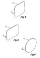
- the method for producing a shock absorber according to the present invention will be described below, which method comprises as a first step providing a planar sheet part 110 (shown in Figures 4 to 6 ) of a metallic material, such as steel only by way of example, with an initial thickness Gi and an initial outline.
- This planar sheet part 110 will be used as a starting material and can have different initial outlines.
- the initial outline of the planar sheet part 110 can be according to the final outline desired for the finished shock absorber, in which case the initial outline will not be altered by the subsequent processes.
- Figure 4 shows a planar sheet part 110 with a square initial outline, preferably with rounded corners
- Figure 5 shows a planar sheet part 110 with a rectangular initial outline, also with rounded corners
- Figure 6 shows a planar sheet part 110 with a circular initial outline.
- any other suitable type of initial outline can be used for the planar sheet part 110.
- the use of a planar sheet part 110 with an initial outline that is larger than the desired final outline, which will be cut in a subsequent operation as explained below, has also been foreseen.
- the planar sheet part 110 shown in Figures 4 to 6 does not include the openings 4 and 13 because these openings can be advantageously formed in a subsequent operation.
- the mentioned first step of providing a planar sheet part 110 described above is common to all the embodiments of the method of the present invention.
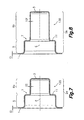
- the second step of the method comprises forming the mentioned planar sheet part 100 to the shape of a partially formed part 120 or preform ( Figure 7 ) made up of a plate 1, a provisional hollow portion 2a extending from said plate 1 with a revolution shape with respect to an axis E perpendicular to the plate 1, and an end wall 3 closing an end of said provisional hollow portion 2a opposite to the plate 1.
- the step of forming the planar sheet part 110 to the shape of the partially formed part 120 is carried out by using a drawing technique by which a general thickness of the partially formed part 120 is obtained that is substantially the same as said initial thickness Gi.
- the partially formed part 120 has been formed by drawing such that the provisional hollow portion 2a has a first section 5 extending from the plate 1, a second section 6a after said first section 5 and connected with the end wall 3, and a transition section 7 connecting said first and second sections 5, 6a, where the first section 5 has an average diameter that is greater than the average diameter of the second section 6a.
- the mentioned transition section 7 is formed in the form of an annular step 11 with a planar portion parallel to the plate 1. All the transition edges between the plate 1, the different sections 5, 6a, 7 and the end wall 3 are preferably rounded.
- the mentioned drawing operation is also suitable for forming the mentioned openings 4, 13 of plate 1 and the of the end wall 3 respectively, as well the cutting of the initial outline of plate 1 so as to produce the desired final outline, if this were the case.
- Figure 8 illustrates the third and last step of this embodiment of the method of the invention, which comprises elongating a substantial part of the second section 6a of the provisional hollow portion 2a of the partially formed part 120 until a formed part 130 is obtained made up of the plate 1, an elongated hollow portion 2a extending from the plate 1 with a revolution shape with respect to the axis E, and the end wall 3 closing an end of said elongated hollow portion 2b opposite to the plate, where the elongated hollow portion 2b comprises the first section 5 and the transition section 7 which have not been altered, and an elongated second section 6b.
- the elongated second section 6b is longer than the second section 6a and therefore the elongated hollow portion 2b of the formed part 130 is longer than the provisional hollow portion 2a of the partially formed part 120.
- the step of elongating the second section 6a of the provisional hollow portion 2a of the partially formed part 120 further comprises making the wall of the second section 6a of the provisional hollow portion 2a thinner.
- the first and second sections 5, 6a of the partially formed part 120 are substantially cylindrical, although for the purposes of the embodiment of the present invention, it is only essential for the second section 6a to be cylindrical.
- a suitable technique for carrying out the third step of the method described above is a direct or reverse cylindrical spinning technique with a flow of material by which the elongated second section 6b of the provisional hollow portion 2b of the formed part 130 is longer and with a final thickness Gf that is thinner than the initial thickness Gi.
- the mentioned wavy annular step 12 has an S-shaped cross section which is not altered during the performance of the third and last step of the method consisting of elongating and thinning the second section 6a of the provisional hollow portion 2a of the partially formed part 120 until the elongated second section 6b of the elongated hollow portion 2b of the formed part 130 is provided, such that the formed part 130 shown in Figure 10 includes this same wavy annular step 12 connected to the end of the first section 5 and the base of the elongated second section 6b.
- the second step of the method comprises forming the planar sheet part 110 by drawing to the shape of a partially formed part 120 shown in Figure 11 which has a provisional hollow portion 2a with a single conical section 8a with a larger diameter end adjacent to the plate 1 and a smaller diameter end away form the plate 1 and connected to the closing wall 3.
- the closing wall 3 is substantially parallel to the plate 1 and the transition edges between the plate 1, the conical section 8a and the closing wall 3 are rounded.
- the thickness of the wall of the conical section 8a and the rest of the partially formed part 120 is substantially the same as the thickness Gi of the planar sheet part 110 used as the starting material.
- the drawing process is also suitable for forming the openings 4, 13 of the plate 1 and of the end wall 3 respectively, as well as the cutting of the initial outline of the plate 1 so as to produce the desired final outline, if this were the case.
- the third step of this embodiment of the method of the present invention is illustrated in Figure 12 and comprises elongating said single conical section 8a of the provisional hollow portion 2a of the partially formed part 120 until producing a second partially formed part 125 with a plate 1 from which there extends a single elongated conical section 8b which is closed in its end opposite to the plate 1 by the end wall 3.
- a suitable technique for carrying out this third step of the method is a conical spinning technique consisting of placing the first partially formed part 120 in a first dolly 15 concentrically fixed to the plate of a lathe (not shown) and making rollers 16 move forward pressing the material of the first partially formed part 120 against the surface of said first dolly 15 while the partially formed part 120 and the first dolly 15 are made to turn by the lathe.
- the partially formed part 120 is secured to the first dolly 15 by an axial live center 17.
- the mentioned surface of the first dolly 15 has a shape adapted to the revolution shape with respect to the axis E desired for the second partially formed part 125.
- the wall of the mentioned elongated conical section 8b of the second partially formed part 125 results with a final thickness Gf that is thinner than the initial thickness Gi and the initial coning angle of the conical section 8a of the first partially formed part 120 results slightly reduced in the elongated conical section 8b of the second partially formed part 125 shown in Figure 12 .
- a suitable coning angle for the elongated conical section 8b of the second partially formed part 125 will generally not exceed 15° (inclination of the wall with respect to the axis E).
- This fourth step comprises forming one or more annular channels 9 in said single elongated conical section 8b of the elongated hollow portion 2b of the second partially formed part 125 by means of a lathe forming technique by means of rollers so as to produce the formed part 130 shown in Figure 13 .
- an inner part of the wall of the elongated conical section 8b of the second partially formed part 125 is supported on a second dolly 18 inserted in the elongated hollow portion 2b and coaxially fixed to the plate of a lathe (not shown).
- the second dolly 18 has a conical outer surface in which annular runners 18a configured according to the inner profile of the annular channels 9 which are wanted to be formed in the elongated conical section 8b are formed.
- the coning angle of the second dolly 18 is identical to the coning angle of the elongated conical section 8b.
- the average diameter of the second dolly 18 is much smaller than the average diameter of the elongated conical section 8b such that the axis E of the partially formed part 125 is displaced from the axis of the lathe Et.
- An axial live center 19 aligned with the axis of the lathe A1 secures the second partially formed part 125 to the second dolly 18.
- roller 20 assembled on a moveable member 21, which roller has annular protrusions 20a configured according to the inner profile of the annular channels 9 which are desired to be formed in the elongated conical section 8b and opposite to the mentioned annular runners 18a of the second dolly 18a.
- the mentioned roller 20 is applied against the wall of the elongated conical section 8b of the second partially formed part 125 so as to produce a formed part 130, shown in Figure 13 , made up of the plate 1, an elongated hollow portion 2b with a single conical section 8b extending from the plate 1 and in which there is formed a series of annular channels 9, and the end wall 3 closing an end of said elongated hollow portion 2b opposite to the plate 1.
- the wall of the conical section 8b, including the annular channels 9, has a thickness that is thinner than the initial thickness Gi of the planar sheet part 110 used as the starting material, said initial thickness Gi being substantially the same as the thickness of the plate 1 and of a transition area between the plate 1 and the elongated conical section 8b of the formed part 130.
- first, second and third steps of another additional embodiment of the method of the invention similar to the one described above in relation to Figures 11 to 13 are described below.
- the second step comprises forming the planar sheet part 110 directly by a first conical spinning process until the partially formed part 120 (on the right part of Figure 14 ) is produced, which part is made up of a plate 1 from which there extends a provisional hollow portion 2a and an end wall 3 closing said provisional hollow portion 2a, the provisional hollow portion 2a being formed by a single conical section 10a having a larger diameter end connected to the plate 1 and a smaller diameter end connected to the end wall 3.
- the provisional hollow portion 2a of the partially formed part 120 has a provisional thickness Gp that is thinner than said initial thickness Gi and a first coning angle A1.
- Figure 15 illustrates the third step of this embodiment of the present invention, which comprises elongating the mentioned single conical section 10a of the provisional hollow portion 2a of the partially formed part 120 (on the left part of Figure 15 ) by means of a second conical spinning operation so as to produce a second partially formed part 125 (on the right part of Figure 15 ) made up of the plate 1 from which there extends an elongated hollow portion 2b and the end wall 3 closing said elongated hollow portion 2b, the elongated hollow portion 2b being formed by a single elongated conical section 10b having a final thickness Gf that is thinner than said provisional thickness Gp and a second coning angle A2 smaller than said first coning angle A1 of the provisional conical section 10a of the partially formed part 120.
- This additional embodiment of the method of the present invention include a fourth step which comprises forming one or more annular channels (not shown) in said single elongated conical section 10b of the elongated hollow portion 2b of the second partially formed part 125 by means of a lathe forming technique by rollers similar to the one described above in relation to Figure 13 so as to produce a formed part 130 with shape features similar to those of said formed part 130 shown in figure 13 .
- the essential features of the shock absorber of the present invention are that it is formed by a single part defining a plate 1 from which there extends an elongated hollow portion 2b having a revolution shape with respect to an axis E perpendicular to said plate 1, and that at least one section of the elongated hollow portion 2b has a second thickness Gf that is thinner than a first thickness Gi of the plate 1.
- a shock absorber including the mentioned essential features can be produced by any one of the aforementioned embodiments of the method of the present invention.
- a formed part 130 is inevitably obtained, which part includes an end wall 3 completely or partially closing an end of the elongated hollow portion 2b opposite to the plate 1, said end wall 3 being integral with the same single part as the plate 1 and the elongated hollow portion 2b.
- the method can include as an additional step a cutting operation transverse to the axis E in order to eliminate the end wall 3.
- the shock absorber preferably includes the end wall 3, which can have a planar portion parallel to the plate 1 so as to facilitate its fixing to a bumper crossbeam in the manner explained above in relation to Figures 1 and 2 .
- the shock absorber preferably includes one or more configurations 9, 11, 12 intended to bring about a controlled deformation of the elongated hollow portion 2b in the event of an impact, i.e., in the event that an axial force above a predetermined threshold is applied, for example, to the end wall 3.
- These controlled deformation techniques can be, for example, in the form of the annular steps 11 and 12 forming part of the transition section 7 described in relation to Figures 7-8 and 9-10 respectively, or in the form of the annular channels 9 described in relation to Figure 13 .
Landscapes
- Engineering & Computer Science (AREA)
- Mechanical Engineering (AREA)
- General Engineering & Computer Science (AREA)
- Shaping Metal By Deep-Drawing, Or The Like (AREA)
- Vibration Dampers (AREA)
- Buildings Adapted To Withstand Abnormal External Influences (AREA)
- Chair Legs, Seat Parts, And Backrests (AREA)
Applications Claiming Priority (1)
| Application Number | Priority Date | Filing Date | Title |
|---|---|---|---|
| PCT/ES2006/000432 WO2008012376A1 (es) | 2006-07-21 | 2006-07-21 | Método para producir un absorbedor de choques y absorbedor de choques obtenido |
Publications (2)
| Publication Number | Publication Date |
|---|---|
| EP2045141A1 true EP2045141A1 (de) | 2009-04-08 |
| EP2045141B1 EP2045141B1 (de) | 2010-10-27 |
Family
ID=37852358
Family Applications (1)
| Application Number | Title | Priority Date | Filing Date |
|---|---|---|---|
| EP06807880A Active EP2045141B1 (de) | 2006-07-21 | 2006-07-21 | Verfahren zur herstellung eines stossdämpfers und erhaltener stossdämpfer |
Country Status (6)
| Country | Link |
|---|---|
| US (1) | US8359893B2 (de) |
| EP (1) | EP2045141B1 (de) |
| AT (1) | ATE485972T1 (de) |
| DE (1) | DE602006017903D1 (de) |
| ES (1) | ES2354198T3 (de) |
| WO (1) | WO2008012376A1 (de) |
Cited By (2)
| Publication number | Priority date | Publication date | Assignee | Title |
|---|---|---|---|---|
| EP2298610A1 (de) * | 2010-05-06 | 2011-03-23 | ISE Automotive GmbH | Crashelement |
| DE102017218393A1 (de) | 2017-10-13 | 2019-04-18 | Thyssenkrupp Ag | Träger für eine Stoßfängervorrichtung eines Kraftfahrzeugs und Verfahren zur Herstellung eines Trägers für eine derartige Stoßfängervorrichtung |
Families Citing this family (8)
| Publication number | Priority date | Publication date | Assignee | Title |
|---|---|---|---|---|
| JP5587698B2 (ja) * | 2010-07-30 | 2014-09-10 | アイシン精機株式会社 | 車両用バンパ装置 |
| GB201016611D0 (en) * | 2010-10-01 | 2010-11-17 | Cambridge Entpr Ltd | Spin forming and apparatus for manufacturing articles by spin forming |
| US8356506B2 (en) * | 2011-02-25 | 2013-01-22 | Szuba Consulting, Inc. | Method of forming industrial housings |
| KR20130047281A (ko) * | 2011-10-31 | 2013-05-08 | 엘지이노텍 주식회사 | 카메라 모듈 |
| DE102013110528A1 (de) * | 2013-09-24 | 2015-03-26 | Thyssenkrupp Steel Europe Ag | Verfahren zum Herstellen eines Verbindungselements sowie Verbindungselement |
| US10723271B2 (en) * | 2018-11-09 | 2020-07-28 | GM Global Technology Operations LLC | Running board configured for absorbing energy and method of forming same |
| US20210041003A1 (en) * | 2019-08-09 | 2021-02-11 | Qiusheng Gao | Safe protection equipment for all vehicles and drivers |
| EP3858684B1 (de) * | 2020-01-28 | 2025-03-05 | Outokumpu Oyj | Aufgeweitetes rohr für eine kraftfahrzeug-crashbox und zugehöriges herstellungsverfahren |
Family Cites Families (20)
| Publication number | Priority date | Publication date | Assignee | Title |
|---|---|---|---|---|
| US1647185A (en) * | 1920-08-31 | 1927-11-01 | American Radiator Co | Method of producing expansible-collapsible elements |
| US2044711A (en) * | 1924-11-11 | 1936-06-16 | Bridgeport Thermostat Company | Method of and apparatus for making corrugated diaphragms |
| US2932890A (en) * | 1955-01-31 | 1960-04-19 | Lodge & Shipley Co | Metal working |
| US2925116A (en) * | 1956-06-25 | 1960-02-16 | William J Eberle | Method of and apparatus for producing flexible boot flashing |
| US3046924A (en) * | 1957-04-23 | 1962-07-31 | Commercial Shearing | Apparatus for spin extruding metal articles |
| US3120206A (en) * | 1959-03-09 | 1964-02-04 | Lodge & Shipley Co | Metal working |
| US3184940A (en) * | 1959-03-09 | 1965-05-25 | Lodge & Shipley Co | Metal working |
| US3740986A (en) * | 1969-01-08 | 1973-06-26 | L Schmid | Ball joint especially for steering devices and wheel suspensions of motor vehicles |
| US5740609A (en) * | 1995-12-08 | 1998-04-21 | Motor Wheel Corporation | Method of making one-piece vehicle wheels and the like |
| DE19814842A1 (de) * | 1998-04-02 | 1999-10-07 | Wagon Automotive Gmbh | Aufpralldämpfer |
| JP2000240707A (ja) | 1999-02-23 | 2000-09-05 | Showa Alum Corp | 金属製衝撃吸収用中空材 |
| FR2792384B1 (fr) * | 1999-04-15 | 2001-06-01 | Lorraine Laminage | Organe absorbeur de choc et procede de fabrication |
| JP3406293B2 (ja) * | 1999-12-03 | 2003-05-12 | 株式会社ディムコ | 金属環状体並びにその製造方法 |
| DE10002379B4 (de) * | 2000-01-20 | 2006-01-19 | Benteler Ag | Stoßfänger |
| JP2002331888A (ja) * | 2001-05-10 | 2002-11-19 | Om Kogyo Kk | バンパ取付構造 |
| US6648384B2 (en) * | 2001-09-27 | 2003-11-18 | Shape Corporation | Bumper crush tower with rings of varied strength |
| US6942262B2 (en) * | 2001-09-27 | 2005-09-13 | Shape Corporation | Tubular energy management system for absorbing impact energy |
| JP4219184B2 (ja) * | 2003-02-06 | 2009-02-04 | 株式会社アステア | 衝撃吸収装置の取付構造 |
| US7152708B2 (en) * | 2003-08-20 | 2006-12-26 | Gkn Driveline North America, Inc. | Propshaft with improved crash-worthiness |
| CA2579504A1 (en) * | 2004-09-07 | 2006-03-16 | Shape Corporation | Plastic energy management beam |
-
2006
- 2006-07-21 WO PCT/ES2006/000432 patent/WO2008012376A1/es not_active Ceased
- 2006-07-21 DE DE602006017903T patent/DE602006017903D1/de active Active
- 2006-07-21 EP EP06807880A patent/EP2045141B1/de active Active
- 2006-07-21 AT AT06807880T patent/ATE485972T1/de not_active IP Right Cessation
- 2006-07-21 ES ES06807880T patent/ES2354198T3/es active Active
-
2009
- 2009-01-21 US US12/356,629 patent/US8359893B2/en active Active
Non-Patent Citations (1)
| Title |
|---|
| See references of WO2008012376A1 * |
Cited By (3)
| Publication number | Priority date | Publication date | Assignee | Title |
|---|---|---|---|---|
| EP2298610A1 (de) * | 2010-05-06 | 2011-03-23 | ISE Automotive GmbH | Crashelement |
| DE102017218393A1 (de) | 2017-10-13 | 2019-04-18 | Thyssenkrupp Ag | Träger für eine Stoßfängervorrichtung eines Kraftfahrzeugs und Verfahren zur Herstellung eines Trägers für eine derartige Stoßfängervorrichtung |
| DE102017218393B4 (de) | 2017-10-13 | 2024-10-02 | Thyssenkrupp Ag | Träger für eine Stoßfängervorrichtung eines Kraftfahrzeugs und Verfahren zur Herstellung eines Trägers für eine derartige Stoßfängervorrichtung |
Also Published As
| Publication number | Publication date |
|---|---|
| WO2008012376A1 (es) | 2008-01-31 |
| ES2354198T3 (es) | 2011-03-10 |
| EP2045141B1 (de) | 2010-10-27 |
| US20090174197A1 (en) | 2009-07-09 |
| ATE485972T1 (de) | 2010-11-15 |
| US8359893B2 (en) | 2013-01-29 |
| DE602006017903D1 (de) | 2010-12-09 |
Similar Documents
| Publication | Publication Date | Title |
|---|---|---|
| US8359893B2 (en) | Method for producing a shock absorber and shock absorber thus obtained | |
| US6216509B1 (en) | Hydroformed tubular member and method of hydroforming tubular members | |
| JP5244075B2 (ja) | 筒状部材の製造方法 | |
| EP2213520B1 (de) | Energieabsorber für eine fahrzeugstossfängeranordnung und herstellungsverfahren dafür | |
| US20190143775A1 (en) | Coupling structure, coupling member having coupling structure, and method for manufacturing coupling member having coupling structure | |
| JP5191613B2 (ja) | 車両用ホイールリムの製造方法 | |
| JP6233402B2 (ja) | ラックの製造方法およびラックの製造装置 | |
| JP2009184460A (ja) | 車両用リンク部品 | |
| JP2010149182A5 (de) | ||
| KR101152093B1 (ko) | 비틀림 프로파일 형상의 자동차부품을 제조하기 위한 방법 | |
| KR101111953B1 (ko) | 증육된 벽 부위를 가진 보스의 성형방법 및 그를 위한 금형장치 | |
| JP2011016193A (ja) | ホイールナットレンチ並びにその製造方法 | |
| EP2025424B1 (de) | Verfahren zur Herstellung eines rohrförmigen Tragprofils für einen Instrumententräger | |
| US20180170156A1 (en) | Door impact beam and manufacturing method thereof | |
| EP3604087B1 (de) | Fahrzeugbauteil und verfahren zur herstellung davon | |
| WO2015041009A1 (ja) | プレス成形品及びプレス成形品の製造方法並びにプレス成形品の製造装置 | |
| JP2008138864A (ja) | ラック及びその製造方法 | |
| US7454942B2 (en) | Hollow molded part with closed cross-section and a reinforcement | |
| JP4429117B2 (ja) | アルミニウム合金製自動車用ホイールリムの製造方法 | |
| EP4121230B1 (de) | Dornanordnung zur verdickung von randabschnitten in einer rohrinnenfläche | |
| EP1979183B1 (de) | Herstellungsverfahren für einen autoaufprallschutz mit integrierten halterungen | |
| DE102010014537B4 (de) | Strukturbauteil für einen Kraftwagen und Verfahren zu dessen Herstellung | |
| WO2011125968A1 (ja) | 車両用ホイールリムの製造方法 | |
| CN109803877B (zh) | 仪表板横梁、托架组及仪表板横梁接合体 | |
| JP4297213B2 (ja) | フランジ付き管状部材の製造方法 |
Legal Events
| Date | Code | Title | Description |
|---|---|---|---|
| PUAI | Public reference made under article 153(3) epc to a published international application that has entered the european phase |
Free format text: ORIGINAL CODE: 0009012 |
|
| 17P | Request for examination filed |
Effective date: 20090123 |
|
| AK | Designated contracting states |
Kind code of ref document: A1 Designated state(s): AT BE BG CH CY CZ DE DK EE ES FI FR GB GR HU IE IS IT LI LT LU LV MC NL PL PT RO SE SI SK TR |
|
| AX | Request for extension of the european patent |
Extension state: AL BA HR MK RS |
|
| 17Q | First examination report despatched |
Effective date: 20100104 |
|
| GRAP | Despatch of communication of intention to grant a patent |
Free format text: ORIGINAL CODE: EPIDOSNIGR1 |
|
| GRAS | Grant fee paid |
Free format text: ORIGINAL CODE: EPIDOSNIGR3 |
|
| GRAA | (expected) grant |
Free format text: ORIGINAL CODE: 0009210 |
|
| AK | Designated contracting states |
Kind code of ref document: B1 Designated state(s): AT BE BG CH CY CZ DE DK EE ES FI FR GB GR HU IE IS IT LI LT LU LV MC NL PL PT RO SE SI SK TR |
|
| REG | Reference to a national code |
Ref country code: GB Ref legal event code: FG4D |
|
| REG | Reference to a national code |
Ref country code: CH Ref legal event code: EP |
|
| REG | Reference to a national code |
Ref country code: IE Ref legal event code: FG4D |
|
| REF | Corresponds to: |
Ref document number: 602006017903 Country of ref document: DE Date of ref document: 20101209 Kind code of ref document: P |
|
| REG | Reference to a national code |
Ref country code: NL Ref legal event code: VDEP Effective date: 20101027 |
|
| REG | Reference to a national code |
Ref country code: ES Ref legal event code: FG2A Effective date: 20110228 |
|
| LTIE | Lt: invalidation of european patent or patent extension |
Effective date: 20101027 |
|
| PG25 | Lapsed in a contracting state [announced via postgrant information from national office to epo] |
Ref country code: LT Free format text: LAPSE BECAUSE OF FAILURE TO SUBMIT A TRANSLATION OF THE DESCRIPTION OR TO PAY THE FEE WITHIN THE PRESCRIBED TIME-LIMIT Effective date: 20101027 |
|
| PG25 | Lapsed in a contracting state [announced via postgrant information from national office to epo] |
Ref country code: PT Free format text: LAPSE BECAUSE OF FAILURE TO SUBMIT A TRANSLATION OF THE DESCRIPTION OR TO PAY THE FEE WITHIN THE PRESCRIBED TIME-LIMIT Effective date: 20110228 Ref country code: IS Free format text: LAPSE BECAUSE OF FAILURE TO SUBMIT A TRANSLATION OF THE DESCRIPTION OR TO PAY THE FEE WITHIN THE PRESCRIBED TIME-LIMIT Effective date: 20110227 Ref country code: AT Free format text: LAPSE BECAUSE OF FAILURE TO SUBMIT A TRANSLATION OF THE DESCRIPTION OR TO PAY THE FEE WITHIN THE PRESCRIBED TIME-LIMIT Effective date: 20101027 Ref country code: FI Free format text: LAPSE BECAUSE OF FAILURE TO SUBMIT A TRANSLATION OF THE DESCRIPTION OR TO PAY THE FEE WITHIN THE PRESCRIBED TIME-LIMIT Effective date: 20101027 Ref country code: LV Free format text: LAPSE BECAUSE OF FAILURE TO SUBMIT A TRANSLATION OF THE DESCRIPTION OR TO PAY THE FEE WITHIN THE PRESCRIBED TIME-LIMIT Effective date: 20101027 Ref country code: SE Free format text: LAPSE BECAUSE OF FAILURE TO SUBMIT A TRANSLATION OF THE DESCRIPTION OR TO PAY THE FEE WITHIN THE PRESCRIBED TIME-LIMIT Effective date: 20101027 Ref country code: SI Free format text: LAPSE BECAUSE OF FAILURE TO SUBMIT A TRANSLATION OF THE DESCRIPTION OR TO PAY THE FEE WITHIN THE PRESCRIBED TIME-LIMIT Effective date: 20101027 Ref country code: BG Free format text: LAPSE BECAUSE OF FAILURE TO SUBMIT A TRANSLATION OF THE DESCRIPTION OR TO PAY THE FEE WITHIN THE PRESCRIBED TIME-LIMIT Effective date: 20110127 Ref country code: NL Free format text: LAPSE BECAUSE OF FAILURE TO SUBMIT A TRANSLATION OF THE DESCRIPTION OR TO PAY THE FEE WITHIN THE PRESCRIBED TIME-LIMIT Effective date: 20101027 |
|
| PG25 | Lapsed in a contracting state [announced via postgrant information from national office to epo] |
Ref country code: BE Free format text: LAPSE BECAUSE OF FAILURE TO SUBMIT A TRANSLATION OF THE DESCRIPTION OR TO PAY THE FEE WITHIN THE PRESCRIBED TIME-LIMIT Effective date: 20101027 Ref country code: GR Free format text: LAPSE BECAUSE OF FAILURE TO SUBMIT A TRANSLATION OF THE DESCRIPTION OR TO PAY THE FEE WITHIN THE PRESCRIBED TIME-LIMIT Effective date: 20110128 |
|
| PG25 | Lapsed in a contracting state [announced via postgrant information from national office to epo] |
Ref country code: CZ Free format text: LAPSE BECAUSE OF FAILURE TO SUBMIT A TRANSLATION OF THE DESCRIPTION OR TO PAY THE FEE WITHIN THE PRESCRIBED TIME-LIMIT Effective date: 20101027 Ref country code: EE Free format text: LAPSE BECAUSE OF FAILURE TO SUBMIT A TRANSLATION OF THE DESCRIPTION OR TO PAY THE FEE WITHIN THE PRESCRIBED TIME-LIMIT Effective date: 20101027 |
|
| PG25 | Lapsed in a contracting state [announced via postgrant information from national office to epo] |
Ref country code: SK Free format text: LAPSE BECAUSE OF FAILURE TO SUBMIT A TRANSLATION OF THE DESCRIPTION OR TO PAY THE FEE WITHIN THE PRESCRIBED TIME-LIMIT Effective date: 20101027 Ref country code: PL Free format text: LAPSE BECAUSE OF FAILURE TO SUBMIT A TRANSLATION OF THE DESCRIPTION OR TO PAY THE FEE WITHIN THE PRESCRIBED TIME-LIMIT Effective date: 20101027 Ref country code: DK Free format text: LAPSE BECAUSE OF FAILURE TO SUBMIT A TRANSLATION OF THE DESCRIPTION OR TO PAY THE FEE WITHIN THE PRESCRIBED TIME-LIMIT Effective date: 20101027 Ref country code: RO Free format text: LAPSE BECAUSE OF FAILURE TO SUBMIT A TRANSLATION OF THE DESCRIPTION OR TO PAY THE FEE WITHIN THE PRESCRIBED TIME-LIMIT Effective date: 20101027 |
|
| PLBE | No opposition filed within time limit |
Free format text: ORIGINAL CODE: 0009261 |
|
| STAA | Information on the status of an ep patent application or granted ep patent |
Free format text: STATUS: NO OPPOSITION FILED WITHIN TIME LIMIT |
|
| 26N | No opposition filed |
Effective date: 20110728 |
|
| REG | Reference to a national code |
Ref country code: DE Ref legal event code: R097 Ref document number: 602006017903 Country of ref document: DE Effective date: 20110728 |
|
| PG25 | Lapsed in a contracting state [announced via postgrant information from national office to epo] |
Ref country code: IT Free format text: LAPSE BECAUSE OF FAILURE TO SUBMIT A TRANSLATION OF THE DESCRIPTION OR TO PAY THE FEE WITHIN THE PRESCRIBED TIME-LIMIT Effective date: 20101027 |
|
| PG25 | Lapsed in a contracting state [announced via postgrant information from national office to epo] |
Ref country code: MC Free format text: LAPSE BECAUSE OF NON-PAYMENT OF DUE FEES Effective date: 20110731 |
|
| REG | Reference to a national code |
Ref country code: CH Ref legal event code: PL |
|
| GBPC | Gb: european patent ceased through non-payment of renewal fee |
Effective date: 20110721 |
|
| REG | Reference to a national code |
Ref country code: IE Ref legal event code: MM4A |
|
| PG25 | Lapsed in a contracting state [announced via postgrant information from national office to epo] |
Ref country code: CH Free format text: LAPSE BECAUSE OF NON-PAYMENT OF DUE FEES Effective date: 20110731 Ref country code: LI Free format text: LAPSE BECAUSE OF NON-PAYMENT OF DUE FEES Effective date: 20110731 |
|
| PG25 | Lapsed in a contracting state [announced via postgrant information from national office to epo] |
Ref country code: GB Free format text: LAPSE BECAUSE OF NON-PAYMENT OF DUE FEES Effective date: 20110721 |
|
| PG25 | Lapsed in a contracting state [announced via postgrant information from national office to epo] |
Ref country code: IE Free format text: LAPSE BECAUSE OF NON-PAYMENT OF DUE FEES Effective date: 20110721 |
|
| PG25 | Lapsed in a contracting state [announced via postgrant information from national office to epo] |
Ref country code: CY Free format text: LAPSE BECAUSE OF EXPIRATION OF PROTECTION Effective date: 20101027 Ref country code: LU Free format text: LAPSE BECAUSE OF NON-PAYMENT OF DUE FEES Effective date: 20110721 |
|
| PG25 | Lapsed in a contracting state [announced via postgrant information from national office to epo] |
Ref country code: TR Free format text: LAPSE BECAUSE OF FAILURE TO SUBMIT A TRANSLATION OF THE DESCRIPTION OR TO PAY THE FEE WITHIN THE PRESCRIBED TIME-LIMIT Effective date: 20101027 |
|
| PG25 | Lapsed in a contracting state [announced via postgrant information from national office to epo] |
Ref country code: HU Free format text: LAPSE BECAUSE OF FAILURE TO SUBMIT A TRANSLATION OF THE DESCRIPTION OR TO PAY THE FEE WITHIN THE PRESCRIBED TIME-LIMIT Effective date: 20101027 |
|
| REG | Reference to a national code |
Ref country code: FR Ref legal event code: PLFP Year of fee payment: 11 |
|
| REG | Reference to a national code |
Ref country code: FR Ref legal event code: PLFP Year of fee payment: 12 |
|
| REG | Reference to a national code |
Ref country code: FR Ref legal event code: PLFP Year of fee payment: 13 |
|
| REG | Reference to a national code |
Ref country code: DE Ref legal event code: R082 Ref document number: 602006017903 Country of ref document: DE Representative=s name: ZEITLER VOLPERT KANDLBINDER PATENT- UND RECHTS, DE Ref country code: DE Ref legal event code: R081 Ref document number: 602006017903 Country of ref document: DE Owner name: AUTOTECH ENGINEERING, S.L., ES Free format text: FORMER OWNER: AUTOTECH ENGINEERING, A.I.E., ABADINO, VIZCAYA, ES Ref country code: DE Ref legal event code: R082 Ref document number: 602006017903 Country of ref document: DE Representative=s name: ZEITLER VOLPERT KANDLBINDER PATENTANWAELTE PAR, DE |
|
| PGFP | Annual fee paid to national office [announced via postgrant information from national office to epo] |
Ref country code: FR Payment date: 20220725 Year of fee payment: 17 |
|
| REG | Reference to a national code |
Ref country code: DE Ref legal event code: R082 Ref document number: 602006017903 Country of ref document: DE Representative=s name: KANDLBINDER, MARKUS, DIPL.-PHYS., DE |
|
| PG25 | Lapsed in a contracting state [announced via postgrant information from national office to epo] |
Ref country code: FR Free format text: LAPSE BECAUSE OF NON-PAYMENT OF DUE FEES Effective date: 20230731 |
|
| PGFP | Annual fee paid to national office [announced via postgrant information from national office to epo] |
Ref country code: ES Payment date: 20250801 Year of fee payment: 20 |
|
| PGFP | Annual fee paid to national office [announced via postgrant information from national office to epo] |
Ref country code: DE Payment date: 20250729 Year of fee payment: 20 |