EP2045143A1 - Procédé et agencement de limitation de charge d'une ceinture de sécurité - Google Patents
Procédé et agencement de limitation de charge d'une ceinture de sécurité Download PDFInfo
- Publication number
- EP2045143A1 EP2045143A1 EP07117762A EP07117762A EP2045143A1 EP 2045143 A1 EP2045143 A1 EP 2045143A1 EP 07117762 A EP07117762 A EP 07117762A EP 07117762 A EP07117762 A EP 07117762A EP 2045143 A1 EP2045143 A1 EP 2045143A1
- Authority
- EP
- European Patent Office
- Prior art keywords
- belt
- signals
- closing velocity
- sensor
- control module
- Prior art date
- Legal status (The legal status is an assumption and is not a legal conclusion. Google has not performed a legal analysis and makes no representation as to the accuracy of the status listed.)
- Granted
Links
Images
Classifications
-
- B—PERFORMING OPERATIONS; TRANSPORTING
- B60—VEHICLES IN GENERAL
- B60R—VEHICLES, VEHICLE FITTINGS, OR VEHICLE PARTS, NOT OTHERWISE PROVIDED FOR
- B60R21/00—Arrangements or fittings on vehicles for protecting or preventing injuries to occupants or pedestrians in case of accidents or other traffic risks
- B60R21/01—Electrical circuits for triggering passive safety arrangements, e.g. airbags, safety belt tighteners, in case of vehicle accidents or impending vehicle accidents
- B60R21/013—Electrical circuits for triggering passive safety arrangements, e.g. airbags, safety belt tighteners, in case of vehicle accidents or impending vehicle accidents including means for detecting collisions, impending collisions or roll-over
- B60R21/0134—Electrical circuits for triggering passive safety arrangements, e.g. airbags, safety belt tighteners, in case of vehicle accidents or impending vehicle accidents including means for detecting collisions, impending collisions or roll-over responsive to imminent contact with an obstacle, e.g. using radar systems
-
- B—PERFORMING OPERATIONS; TRANSPORTING
- B60—VEHICLES IN GENERAL
- B60R—VEHICLES, VEHICLE FITTINGS, OR VEHICLE PARTS, NOT OTHERWISE PROVIDED FOR
- B60R21/00—Arrangements or fittings on vehicles for protecting or preventing injuries to occupants or pedestrians in case of accidents or other traffic risks
- B60R21/01—Electrical circuits for triggering passive safety arrangements, e.g. airbags, safety belt tighteners, in case of vehicle accidents or impending vehicle accidents
- B60R2021/01204—Actuation parameters of safety arrangents
- B60R2021/01252—Devices other than bags
- B60R2021/01265—Seat belts
- B60R2021/01279—Load limiters
-
- B—PERFORMING OPERATIONS; TRANSPORTING
- B60—VEHICLES IN GENERAL
- B60R—VEHICLES, VEHICLE FITTINGS, OR VEHICLE PARTS, NOT OTHERWISE PROVIDED FOR
- B60R22/00—Safety belts or body harnesses in vehicles
- B60R22/34—Belt retractors, e.g. reels
- B60R22/46—Reels with means to tension the belt in an emergency by forced winding up
- B60R2022/4666—Reels with means to tension the belt in an emergency by forced winding up characterised by electric actuators
Definitions
- the invention relates to a method and a system for limiting the load of a vehicle safety belt in case of an emergency.
- the method and system comprises means for detecting and predicting the severity of a crash in order to adapt the belt force to the crash conditions.
- belt force load limiters i.e. a device which limits the restraining force of a safety seat belt in case of a crash or sudden brake, in vehicles has become more and more common today.
- the purpose of these belt force load limiters is to avoid or reduce injuries on a person seated and belted in a vehicle seat due to an unnecessary hard restraining force from the belt in case of an accident.
- DE 196 04 483 describes a method which takes into account data from the actual crash situation and intends to adapt the force from the belt to be optimized with respect to the forces from the belt working on the seated person and the permissible extension of the belt.
- the present invention provides a method for controlling an Adaptive Belt Load Limiter (ABLL) for a vehicle safety belt in a vehicle which overcomes the deficiencies of the above described system.
- ABLL Adaptive Belt Load Limiter
- the present invention is focused on two essential problems for improving such a system: An early detection of a crash situation and a reliable estimation of the crash scenario such that the ABLL at an early stage is provided with the right control signal.
- the present invention is directed to provide a control system which by the use of an advanced Closing Velocity Sensor (CVS) system is able to detect an upcoming crash situation.
- CVS Closing Velocity Sensor
- the severity of a crash scenario is estimated by a Restraints Control Module (RCM) which further prepares a control signal or control sequence based on the crash severity estimation.
- the control signal is sent to an Adaptive Belt Load Limiter (ABLL) and the control signal may reach the ABLL at an early stage, most preferably before an impact or before the impact is sensed by sensors indicating the actual status of the vehicle.
- ABLL Adaptive Belt Load Limiter
- the prediction of an accident by such a CVS as described above is particularly suitable for controlling the belt load limiter since it is of high importance to be able to accurately decide the appropriate load level before a crash has occurred since the belt will start to function at the same instant the crash situation starts in contrast to an air bag cushion which is intended to be working at a later stage in the accident. Furthermore, the possibility to classify the accident by the use of area specific CVS will make it possible to better predict the estimated impact force or the severity of the crash since there is a great difference in an front offset or angled collision compared to a full frontal impact collision. This information may thus be used to adapt the seat belt restraining force.
- the one or several CVS covers three different spatial areas and are able to distinguish the sensed signals from each area corresponding to a middle front area, a left front area and a right front area.
- An example of a suitable sensor arrangement is for example disclosed in US 2007/0032952 .
- the RCM is provided with ports for data input signals corresponding to vehicle speed and/or acceleration such that a crash severity estimation may be performed based on the sensor signals from the different areas covered by the Closing Velocity Sensor(s), the vehicle speed and/or vehicle acceleration.
- the RCM provided with or connected to a Look Up Table (LUT).
- the LUT comprises a crash type classification scheme, such that different crash types are classified based on the sensor signals from the Closing Velocity Sensor(s) corresponding to the detection of an object in the different areas and a control signal is generated by the RCM by using said LUT.
- the LUT may include different classification such as centre pole crash (only the front centre area indicates an object), offset/angled right crash (only the front right area indicates an object), offset/angled left crash (only the front left area indicates an object) and full frontal crash (all three areas or at least two of the areas are indicated).
- centre pole crash only the front centre area indicates an object
- offset/angled right crash only the front right area indicates an object
- offset/angled left crash only the front left area indicates an object
- full frontal crash all three areas or at least two of the areas are indicated.
- control signal for the left respectively right seat belt load limiters when there is an offset/angled crash situation such that different control signals are sent to the respective left and right side belt load limiters since the impact force is different on the different sides.
- a number of different crash classifications may be done and appropriate control signals for the different types of crashes may be tried out by crash tests and/or simulations such that the RCM is tuned to best control the ABLL.
- the control signal which is obtained from the LUT may either be such that it may be directly sent to the ABLL or may be further processed by the RCM before it is sent to the ABLL.
- the RCM is provided with or connected to several sets of LUTs whereof the appropriate LUT to be used is selected by using at least one of the parameters ego vehicle speed, ego vehicle acceleration, closing velocity of an approaching object or weight of the belted occupant.
- the appropriate LUT to be used is selected by using at least one of the parameters ego vehicle speed, ego vehicle acceleration, closing velocity of an approaching object or weight of the belted occupant.
- LUTs which are selected depending on desired parameters concerning the vehicle and the environment, such that when the relevant conditions of the crash scenario is known or estimated, the right LUT is selected from which a relevant parameter is retrieved to either be further processed by the RCM for creating a control command for the ABLL or used directly as a control signal to the ABLL.
- the control signal from the RCM to the ABLL is a signal which controls the length of the safety belt pay out roll at a standard load level before the force limiter is activated.
- One way of deciding the belt pay out length is to measure the number of revolutions the roll has made.
- the control signal may also indicate a certain time period to lapse before the belt force limiter is activated but in general it is considered to be more accurate to control the length of the belt which has been paid out.
- This control system is in particular designed for a seat belt construction with an ABLL which irreversibly changes the belt force limiting action from a standard state (i.e.
- the invention further relates to a belt force limiting system for performing the method described above, said system comprising one or several Closing Velocity Sensor(s) (CVS) for detecting objects in front of the vehicle.
- CVS Closing Velocity Sensor(s)
- the system further comprises a Restraints Control Module (RCM) connected to the CVS in order to receive sensor input data from the CVS.
- RCM Restraints Control Module
- the RCM is adapted to use the sensor input data in order to generate an output control signal.
- the control signal may of course also be dependent on other parameters than the CVS signals.
- the system further comprises an Adaptive Belt Load Limiter (ABLL) connected to the RCM.
- ABLL Adaptive Belt Load Limiter
- the ABLL is adapted to receive the output control signal from the RCM and effectuate the belt load limiting action.
- the system is characterised in that the one or several Closing Velocity Sensor(s) is capable of sensing the presence of an object in at least two different spatial areas, e.g. in the middle part in front of the vehicle or angled at the right or left side in front of the vehicle.
- the CVS signals from the different areas or zones are kept separate such that area specific signals are generated and the RCM is adapted to generate a control signal to the ABLL which is dependent on the sensed condition in the at least two spatial areas.
- the system shall enable the differentiating of signals originating from different areas and take into consideration from which area a signal is originating when generating the control signal.
- the one or several Closing Velocity Sensor(s) covers three different spatial areas and is able to distinguish the sensed signals from each area corresponding to a middle front area, a left front area and a right front area. It is of course possible to use further sensors or modify the existing sensors in order to specify further, more narrow areas or to cover a larger total zone.
- the system also comprises speed and/or acceleration sensors which are connected to the Restraints Control Module.
- the input signals from these sensors in addition to the signals from the CVS, may also be used for generating the control signal for the Adaptive Belt Load Limiter (ABLL).
- ABLL Adaptive Belt Load Limiter
- the RCM is provided with or connected to one or several Look Up Tables (LUT).
- the LUTs comprises a crash type classification scheme, such that different crash types are classified based on the sensor signals from the CVS corresponding to the detection of an object in the different areas covered by the CVS.
- different LUTs are used depending on at least one of the parameters ego vehicle speed, ego vehicle acceleration, closing velocity of an approaching object or weight of the belted occupant.
- the RCM is adapted to generate a control signal to the ABLL which controls the length of safety belt pay out roll at a standard level before the force limiter is activated.
- the invention further relates to the use of one or several Closing Velocity Sensor(s) capable of sensing the presence of an object in at least two different spatial areas and being able to distinguish the sensed signals from each other for controlling a belt force limiter for a vehicle safety belt in a vehicle.
- the invention is directed to the use of one or several CVS which cover three different spatial areas corresponding to a middle front area, a left front area and a right front area and being able to distinguish the sensed signals from each area.
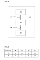
- FIG 1 a schematic drawing shows the main components associated with the present belt load control safety system 101.
- the system 101 comprises a Closing Velocity Sensor (CVS) 102, a Restraints Control Module (RCM) 103 and an Adaptive Belt Load Limiter (ABLL) 104.
- the CVS 102 is specified to be able to detect an object in at least two different areas and a suitable CVS for the present invention is described in figure 3 .
- any CVS able of detecting objects in at least two areas which not are identical, i.e. they do not completely overlap each other but may be either covering totally separate areas or partly overlapping areas, may be used in the system described in figure 1 .
- the CVS 102 is connected to the RCM 103 such that sensor signals from the CVS 102 may be transmitted to the RCM 103 through a connection 105.
- the connection may either be a wire connected to an output port on the CVS 102 and an input port on the RCM 103 or a wireless connection having a sender connected to the CVS 102 and a receiver connected to the RCM 103. It may of course also be possible to have a two way connection or a second connection such that signals may be sent from the RCM 103 to the CVS 102, e.g. control signals in order to set desired parameters for the CVS such as sample interval and/or to control the shape, size and overlapping of different areas.
- connection 105 the essential feature of this connection 105 is that sensor signals from the CVS 102 are transmitted to the RCM 103 while additional use of communication between the CVS 102 and the RCM 103 may be used in addition in order to improve the system 101.
- the RCM 103 is further connected to the ABLL 104 by a connection 106 such that control signals generated by the RCM 103 may be transmitted to the ABLL 104.
- the connection may either be a wire connected to an output port on the RCM 103 and an input port on the ABLL 104 or a wireless connection having a sender connected to the RCM 103 and a receiver connected to the ABLL 104. It may of course also be possible to have a two way connection or a second connection such that signals may be sent from the ABLL 104 to the RCM 103, e.g.
- connection 106 control signals generated by the RCM 103 are transmitted to the ABLL 104 while additional use of communication between the RCM 103 and the ABLL 104 may be used in addition in order to improve the system 101.
- the CVS 102, the RCM 103 and the ABLL 104 are represented as separate units or boxes. It is obvious for the skilled person in the art that for example the CVS 102 and the RCM 103 may be located in the same housing or the RCM and the ABLL 104 are located in a single housing. Furthermore, the RCM 103 need not to be a separate unit but may be a part of a vehicle safety system including numbers of other control functions.
- the system 101 may further have a number of additional features added to the basic features in this drawing representing an embodiment of the invention. It may for example be added further input parameters, such as vehicle speed, acceleration data from accelerometers, weight of an occupant of a seat etc. representing data input which may be relevant for controlling the load of a belt in the vehicle. This may for example be achieved by connecting the RCM to a Local Area Network (LAN) or a Controller Area Network (CAN). There may also be a number of different control algorithms used depending on these input parameters which may be used in addition to the CVS. It is also advisable to use some kind of control function for the sensor signals from the CVS such that the signals represent a certain confidence level.
- LAN Local Area Network
- CAN Controller Area Network
- ABLL Adaptive Belt Load Limiter
- the ABLL is exemplified as being of a kind which may adapt the belt restriction force between two different levels: A first high load level and a second low level.
- the belt is reversibly switched from the high load level to the low load level by the ABLL in response to a control signal from the Restriction Control Module (RCM).
- RCM Restriction Control Module
- a Look Up Table (LUT) is shown.
- the control parameters corresponds to a desired length (in centimetres) of the belt roll to be paid out before the ABLL changes the belt restriction force from its high load level to its low load level.
- the first set of control parameters in the first row corresponds to a stiff collision like a full frontal crash (e.g.
- the second set of control parameters in the second row corresponds to a "soft collision" like an angled, offset collision (e.g. when the same type of CVS as above only senses an object in either the left or right area).
- a certain row in the LUT is selected depending on in which area, or areas, an object was detected.
- the right column (a, b, c or d) may be selected depending on different additional parameters.
- the "a" column may corresponds to a speed of the vehicle of less than 10 km per hour and a closing velocity (detected by the CVS) of less than 20 km/h;
- the "b” column may correspond to a speed of the vehicle of 10 - 20 km/h and a closing velocity of less than 20 km/
- the "c” column may correspond to a speed of the vehicle of less than "20" km/h and a closing velocity of 20 - 40 km/h and the "d” column may correspond to a speed of the vehicle of 20 - 30 km per hour and a closing velocity of less than 40 km/.
- the ABLL will be instructed to allow the belt restriction force to be at the high load level until the belt pay out length indicated in the appropriate place in the LUT is reached.
- the ABLL will switch over to the second low load level where the belt restraining force is lower from the table one can read that in the case of a stiff collision (first row), the safety belt pay out length in high energy absorption mode is longer than for a soft collision (second row) when the other relevant parameters (closing velocity and vehicle speed) are the same, i.e. in the same column.
- Fig. 2 only serves as an explanatory example of how a look up table may be used.
- the LUT will only be used if the vehicle speed is less than 30 km/h and the closing velocity speed sensed by the CVS is less than 40 km/h, otherwise the ABLL will not lower the belt force.
- the adaptive belt force limiter will in this case only be used in less severe crash situations such that it is assured that the belt force limiter not will be used when there is a severe accident which demands the use of a high load level of the belt force restriction.
- the numbers comprised in the LUT shall not be considered as being suitable for all kinds of load limiter in any kind of car but must be adapted for each safety system in dependence on which kind of load limiters which are used and what different levels of restraining forces they have, the maximum allowed distance to pay out the belt and, preferably, to cooperate with other safety systems of the car. Since this LUT only is meant to be an example, it is obvious that there may be several further classifications of accidents, corresponding to the different rows, than the two rows present. There may of course also be further columns using further parameters, e.g.
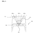
- FIG. 3 an example of spatial positioning of the Closing Velocity Sensor (CVS) 302 within a vehicle 301 is illustrated.
- the CVS 302 is located optionally behind the windscreen 303 at an upper region thereof, although other positions can be adopted if required. More optionally, the CVS 302 is included as part of a Windscreen Electronic Module (WEM) 304.
- the WEM 304 can also include other sensors, for example optical sensors for monitoring headlights of on-coming vehicles so as to provide the vehicle 301 with an automatic headlight-dimming function.
- the CVS 302 is itself synergistically additionally capable of functioning as a precipitation sensor, for example a rain sensor, and as an ambient light sensor.
- a threshold speed and/or a rate of deceleration in crash avoidance or crash mitigation situations can be modified in response to a precipitation condition detected by the CVS 302, for example to enhance controllability of the vehicle 301 in wet or icy conditions.
- the windscreen 303 should be fabricated from a material which allows three pulsed beams of infrared radiation 305a, 305b, 305c to propagate through the windscreen 305 and be subsequently reflected from oncoming objects in front of the vehicle 301 to generate corresponding reflected radiation which is received back at the closing rate (CVS) 302.
- CVS closing rate
- closing velocities of the oncoming objects can be computed at the closing rate sensor 302.
- By sending the signals at different times and/or having different characteristics of the signal sent it may be possible to distinguish the different signals such that information concerning in which area or areas an upcoming object is detected.
- the CVS 302 is designed to be optionally mounted at a relatively high position onto or close to the windscreen 305 of the vehicle 301. Such a mounting position potentially provides an optimal field of view of a region in front of the vehicle 301, namely in a region wherein one or more potential impact hazards are likely to be encountered.
- each beam 305a, 305b, 305c also provides a vertical field of sensing of substantially 8° with an inclination of substantially 4° in respect of a horizontal plane.
- Each sensing sector is provided with a set of three corresponding lenses in the sensor 302.
- light sensitive diodes are employed, each in combination with its three lenses, to sense reflection of the beams 305a, 305b, 305c reflected back to the sensor 302.
- the diodes and their respective lenses are beneficially optically shielded from their corresponding lasers employed for generating the beams 305a, 305b, 305c to reduce direct coupling of optical radiation from the lasers to their respective light sensitive diodes.
- the lasers or at least one of the lasers employed within the sensor 302 optionally exhibit an output radiation wavelength of substantially 905 nanometres and are class I laser category with regard to their radiation power output.
- the CVS 302 provides distance and velocity information regarding one or more oncoming objects in front of the vehicle 301 at an update rate of substantially 100 Hz, namely at 10 millisecond intervals.
- a sensing cycle is optionally implemented in the sensor 302 for each of the sectors.
- the cycle commences by each laser in the sensor 302 providing a burst of laser radiation for emission from the sensor 302.
- the burst has a duration of 2 milliseconds and comprises 100 pulses of radiation, wherein each pulse has a duration of substantially 30 nanoseconds.
- the aforesaid light sensitive diodes are scanned for substantially 100 nanoseconds to derive reflected radiation signals.
- a sum of all intensities in the reflected radiation signals are used for performing a distance calculation, the calculation optionally being implemented using a simple "centre of mass” approach, thereby simplifying computation required.
- a closing velocity can there from be derived.
- the sensor 302 employs time-of-flight (TOF) measurements of IR-laser pulses to calculate relative distances between the vehicle 301 and one or more potentially hazardous objects in front of the vehicle 301; measured distance changes within a well-defined period of time are used to generate relative velocity data and hence aforesaid closing velocity data for the Automatic Belt Load Limiter collision management system.
- TOF time-of-flight
- the CVS 302 can also be implemented using optical or radar Doppler techniques, wherein a portion of reflected radiation from one or more oncoming objects in a direction of travel of the vehicle 301 is mixed at the sensor 302 with a portion of radiation emitted from the sensor 302 towards the one or more oncoming objects to generate a Doppler beat signal from which a measure of closing velocity of the one or more objects to the vehicle 301 can be derived.
Landscapes
- Engineering & Computer Science (AREA)
- Radar, Positioning & Navigation (AREA)
- Remote Sensing (AREA)
- Mechanical Engineering (AREA)
- Air Bags (AREA)
- Automotive Seat Belt Assembly (AREA)
Priority Applications (3)
| Application Number | Priority Date | Filing Date | Title |
|---|---|---|---|
| EP07117762.0A EP2045143B1 (fr) | 2007-10-02 | 2007-10-02 | Procédé et agencement de limitation de charge d'une ceinture de sécurité |
| CN2008101320035A CN101402341B (zh) | 2007-10-02 | 2008-07-16 | 用于安全带的负荷限制的方法和装置 |
| US12/244,647 US20090085340A1 (en) | 2007-10-02 | 2008-10-02 | Method and apparatus for load limiting of a safety belt |
Applications Claiming Priority (1)
| Application Number | Priority Date | Filing Date | Title |
|---|---|---|---|
| EP07117762.0A EP2045143B1 (fr) | 2007-10-02 | 2007-10-02 | Procédé et agencement de limitation de charge d'une ceinture de sécurité |
Publications (2)
| Publication Number | Publication Date |
|---|---|
| EP2045143A1 true EP2045143A1 (fr) | 2009-04-08 |
| EP2045143B1 EP2045143B1 (fr) | 2016-07-27 |
Family
ID=39133821
Family Applications (1)
| Application Number | Title | Priority Date | Filing Date |
|---|---|---|---|
| EP07117762.0A Ceased EP2045143B1 (fr) | 2007-10-02 | 2007-10-02 | Procédé et agencement de limitation de charge d'une ceinture de sécurité |
Country Status (3)
| Country | Link |
|---|---|
| US (1) | US20090085340A1 (fr) |
| EP (1) | EP2045143B1 (fr) |
| CN (1) | CN101402341B (fr) |
Families Citing this family (7)
| Publication number | Priority date | Publication date | Assignee | Title |
|---|---|---|---|---|
| DE102011104925A1 (de) * | 2011-06-18 | 2012-12-20 | Daimler Ag | Kraftfahrzeug mit einer Fahrerassistenzeinheit |
| EP2743142B1 (fr) * | 2012-12-12 | 2020-03-25 | Volvo Car Corporation | Procédé de rappel d'une ceinture de sécurité |
| EP2808693B1 (fr) * | 2013-05-27 | 2019-08-14 | Volvo Car Corporation | Système et procédé permettant de déterminer la position d'un être vivant dans un véhicule |
| JP6658602B2 (ja) * | 2017-02-17 | 2020-03-04 | トヨタ自動車株式会社 | 車両用可変フォースリミッタ制御システム |
| US10286872B2 (en) | 2017-05-03 | 2019-05-14 | Ford Global Technologies, Llc | Energy-absorbing restraint system |
| US10525923B2 (en) * | 2017-09-08 | 2020-01-07 | Ford Global Technologies, Llc | Belt load modulation for vehicle front oblique impacts |
| JP7283130B2 (ja) * | 2019-02-28 | 2023-05-30 | トヨタ自動車株式会社 | フォースリミッタ制御システム |
Citations (4)
| Publication number | Priority date | Publication date | Assignee | Title |
|---|---|---|---|---|
| EP0893313A2 (fr) * | 1997-07-23 | 1999-01-27 | Breed Automotive Technology, Inc. | Dispositif d'enroulement d'une ceinture de sécurité |
| EP1104721A2 (fr) * | 1999-12-01 | 2001-06-06 | TRW Occupant Restraint Systems GmbH & Co. KG | Système de retenue d'un passager |
| WO2001045985A1 (fr) * | 1999-12-21 | 2001-06-28 | Breed Automotive Technology, Inc. | Systeme de securite passive pour vehicule automobile |
| DE10132681C1 (de) * | 2001-07-05 | 2002-08-22 | Bosch Gmbh Robert | Verfahren zur Klassifizierung von einem Hindernis anhand von Precrashsensorsignalen |
Family Cites Families (15)
| Publication number | Priority date | Publication date | Assignee | Title |
|---|---|---|---|---|
| DE50005688D1 (de) * | 2000-05-16 | 2004-04-22 | Daimler Chrysler Ag | Insassenrückhaltesystem |
| US6510914B2 (en) * | 2000-07-26 | 2003-01-28 | Honda Giken Kogyo Kabushiki Kaisha | Obstruction inference apparatus for vehicle |
| US7128343B2 (en) * | 2001-02-06 | 2006-10-31 | Autoliv Asp,Inc. | Safety-belt arrangement |
| US20030076981A1 (en) * | 2001-10-18 | 2003-04-24 | Smith Gregory Hugh | Method for operating a pre-crash sensing system in a vehicle having a counter-measure system |
| US6519519B1 (en) * | 2002-02-01 | 2003-02-11 | Ford Global Technologies, Inc. | Passive countermeasure methods |
| US7130730B2 (en) * | 2002-10-25 | 2006-10-31 | Ford Global Technologies Llc | Sensing strategy for damage mitigation in compatability situations |
| DE10252227A1 (de) * | 2002-11-11 | 2004-05-27 | Robert Bosch Gmbh | Verfahren zur Ansteuerung von Rückhaltemitteln |
| US20050206152A1 (en) * | 2004-03-19 | 2005-09-22 | Trw Vehicle Safety Systems Inc. | Vehicle occupant protection device having shoulder belt load limiters and an associated method |
| US7431333B2 (en) * | 2004-10-13 | 2008-10-07 | Ford Global Technologies, Llc | Occupant safety-restraint system and method for fully deploying an airbag prior to occupant contact |
| US7581757B2 (en) * | 2004-10-19 | 2009-09-01 | Autoliv Asp, Inc. | Retractor with pretensioner |
| US7227474B2 (en) * | 2005-01-25 | 2007-06-05 | Vistoen Global Technologies, Inc. | Object detection system: zone matching and programmability |
| EP1944189B2 (fr) * | 2005-08-04 | 2020-06-03 | Volvo Car Corporation | Système automatique de gestion des collisions |
| US20070233353A1 (en) * | 2006-03-28 | 2007-10-04 | Alexander Kade | Enhanced adaptive cruise control system with forward vehicle collision mitigation |
| US9663052B2 (en) * | 2006-03-30 | 2017-05-30 | Ford Global Technologies, Llc | Method for operating a pre-crash sensing system to deploy airbags using confidence factors prior to collision |
| US8554461B2 (en) * | 2007-02-19 | 2013-10-08 | Ford Global Technologies, Llc | System and method for pre-deploying restraints countermeasures using pre-crash sensing and post-crash sensing |
-
2007
- 2007-10-02 EP EP07117762.0A patent/EP2045143B1/fr not_active Ceased
-
2008
- 2008-07-16 CN CN2008101320035A patent/CN101402341B/zh active Active
- 2008-10-02 US US12/244,647 patent/US20090085340A1/en not_active Abandoned
Patent Citations (4)
| Publication number | Priority date | Publication date | Assignee | Title |
|---|---|---|---|---|
| EP0893313A2 (fr) * | 1997-07-23 | 1999-01-27 | Breed Automotive Technology, Inc. | Dispositif d'enroulement d'une ceinture de sécurité |
| EP1104721A2 (fr) * | 1999-12-01 | 2001-06-06 | TRW Occupant Restraint Systems GmbH & Co. KG | Système de retenue d'un passager |
| WO2001045985A1 (fr) * | 1999-12-21 | 2001-06-28 | Breed Automotive Technology, Inc. | Systeme de securite passive pour vehicule automobile |
| DE10132681C1 (de) * | 2001-07-05 | 2002-08-22 | Bosch Gmbh Robert | Verfahren zur Klassifizierung von einem Hindernis anhand von Precrashsensorsignalen |
Also Published As
| Publication number | Publication date |
|---|---|
| CN101402341B (zh) | 2013-02-27 |
| US20090085340A1 (en) | 2009-04-02 |
| EP2045143B1 (fr) | 2016-07-27 |
| CN101402341A (zh) | 2009-04-08 |
Similar Documents
| Publication | Publication Date | Title |
|---|---|---|
| EP1944189B2 (fr) | Système automatique de gestion des collisions | |
| US8798885B2 (en) | Collision reducing device | |
| EP1428728B1 (fr) | Système de sécurité et méthode pour un véhicule | |
| EP1705078B1 (fr) | Reconaissance d'objets et système de protection pour piétons | |
| US6271747B1 (en) | Method for adjusting the trigger threshold of vehicle occupant protection devices | |
| EP2045143B1 (fr) | Procédé et agencement de limitation de charge d'une ceinture de sécurité | |
| US20060091654A1 (en) | Sensor system with radar sensor and vision sensor | |
| US8335615B2 (en) | Whiplash reduction system | |
| JP2021147042A (ja) | 重み付きアクティブ−パッシブ衝突モード分類を実行する車両安全システムおよび方法 | |
| JP3912163B2 (ja) | 車両の衝突対策システム | |
| JPH10181520A (ja) | 車両における乗客拘束装置用始動装置 | |
| EP2883756B1 (fr) | Système de sécurité et procédé de fonctionnement pour système de sécurité d'un véhicule | |
| JP2021142975A (ja) | 一体型アクティブ−パッシブ正面衝撃制御アルゴリズムを実行する車両安全システム | |
| JP5002406B2 (ja) | 車両の衝突判定装置 | |
| KR20230005556A (ko) | 충돌 경고 장치 및 그것을 포함하는 차량 | |
| US20210142597A1 (en) | Method for determining the severity of a possible collision between a motor vehicle and another vehicle, control apparatus, driver assistance system and a motor vehicle | |
| JP4797463B2 (ja) | 衝突判定装置 | |
| EP2234845B1 (fr) | Système de sécurité pour automobile | |
| KR20140075557A (ko) | 차량 충돌을 예측적으로 감지하는 장치 및 방법 | |
| KR101596995B1 (ko) | 차량의 충격완화 방법 | |
| WO1999010803A1 (fr) | Procede et dispositif permettant d'analyser l'espace entourant des vehicules | |
| KR20250016923A (ko) | 차량추돌에 의한 충격완화장치 및 그에 따른 제어방법 |
Legal Events
| Date | Code | Title | Description |
|---|---|---|---|
| PUAI | Public reference made under article 153(3) epc to a published international application that has entered the european phase |
Free format text: ORIGINAL CODE: 0009012 |
|
| AK | Designated contracting states |
Kind code of ref document: A1 Designated state(s): AT BE BG CH CY CZ DE DK EE ES FI FR GB GR HU IE IS IT LI LT LU LV MC MT NL PL PT RO SE SI SK TR |
|
| AX | Request for extension of the european patent |
Extension state: AL BA HR MK RS |
|
| 17P | Request for examination filed |
Effective date: 20091007 |
|
| AKX | Designation fees paid |
Designated state(s): DE GB SE |
|
| 17Q | First examination report despatched |
Effective date: 20110608 |
|
| RAP1 | Party data changed (applicant data changed or rights of an application transferred) |
Owner name: VOLVO CAR CORPORATION |
|
| GRAP | Despatch of communication of intention to grant a patent |
Free format text: ORIGINAL CODE: EPIDOSNIGR1 |
|
| INTG | Intention to grant announced |
Effective date: 20160219 |
|
| GRAS | Grant fee paid |
Free format text: ORIGINAL CODE: EPIDOSNIGR3 |
|
| GRAA | (expected) grant |
Free format text: ORIGINAL CODE: 0009210 |
|
| AK | Designated contracting states |
Kind code of ref document: B1 Designated state(s): DE GB SE |
|
| REG | Reference to a national code |
Ref country code: GB Ref legal event code: FG4D |
|
| REG | Reference to a national code |
Ref country code: DE Ref legal event code: R096 Ref document number: 602007047153 Country of ref document: DE |
|
| REG | Reference to a national code |
Ref country code: SE Ref legal event code: TRGR |
|
| REG | Reference to a national code |
Ref country code: DE Ref legal event code: R097 Ref document number: 602007047153 Country of ref document: DE |
|
| PLBE | No opposition filed within time limit |
Free format text: ORIGINAL CODE: 0009261 |
|
| STAA | Information on the status of an ep patent application or granted ep patent |
Free format text: STATUS: NO OPPOSITION FILED WITHIN TIME LIMIT |
|
| 26N | No opposition filed |
Effective date: 20170502 |
|
| PGFP | Annual fee paid to national office [announced via postgrant information from national office to epo] |
Ref country code: GR Payment date: 20181212 Year of fee payment: 16 |
|
| PGFP | Annual fee paid to national office [announced via postgrant information from national office to epo] |
Ref country code: GB Payment date: 20181011 Year of fee payment: 12 |
|
| PG25 | Lapsed in a contracting state [announced via postgrant information from national office to epo] |
Ref country code: SE Free format text: LAPSE BECAUSE OF NON-PAYMENT OF DUE FEES Effective date: 20191003 |
|
| GBPC | Gb: european patent ceased through non-payment of renewal fee |
Effective date: 20191002 |
|
| PG25 | Lapsed in a contracting state [announced via postgrant information from national office to epo] |
Ref country code: GB Free format text: LAPSE BECAUSE OF NON-PAYMENT OF DUE FEES Effective date: 20191002 |
|
| REG | Reference to a national code |
Ref country code: DE Ref legal event code: R082 Ref document number: 602007047153 Country of ref document: DE Representative=s name: ZACCO LEGAL RECHTSANWALTSGESELLSCHAFT MBH, DE |
|
| P01 | Opt-out of the competence of the unified patent court (upc) registered |
Effective date: 20231212 |
|
| PGFP | Annual fee paid to national office [announced via postgrant information from national office to epo] |
Ref country code: DE Payment date: 20230920 Year of fee payment: 17 |
|
| REG | Reference to a national code |
Ref country code: DE Ref legal event code: R119 Ref document number: 602007047153 Country of ref document: DE |
|
| PG25 | Lapsed in a contracting state [announced via postgrant information from national office to epo] |
Ref country code: DE Free format text: LAPSE BECAUSE OF NON-PAYMENT OF DUE FEES Effective date: 20250501 |