EP2045149A2 - Renvoi de sangle de ceinture de sécurité, dispositif de ceinture de sécurité et véhicule équipé d'un tel dispositif - Google Patents
Renvoi de sangle de ceinture de sécurité, dispositif de ceinture de sécurité et véhicule équipé d'un tel dispositif Download PDFInfo
- Publication number
- EP2045149A2 EP2045149A2 EP08016272A EP08016272A EP2045149A2 EP 2045149 A2 EP2045149 A2 EP 2045149A2 EP 08016272 A EP08016272 A EP 08016272A EP 08016272 A EP08016272 A EP 08016272A EP 2045149 A2 EP2045149 A2 EP 2045149A2
- Authority
- EP
- European Patent Office
- Prior art keywords
- tube body
- shaft
- seat belt
- anchor
- vehicle
- Prior art date
- Legal status (The legal status is an assumption and is not a legal conclusion. Google has not performed a legal analysis and makes no representation as to the accuracy of the status listed.)
- Granted
Links
Images






Classifications
-
- B—PERFORMING OPERATIONS; TRANSPORTING
- B60—VEHICLES IN GENERAL
- B60R—VEHICLES, VEHICLE FITTINGS, OR VEHICLE PARTS, NOT OTHERWISE PROVIDED FOR
- B60R22/00—Safety belts or body harnesses in vehicles
- B60R22/18—Anchoring devices
- B60R22/185—Anchoring devices with stopping means for acting directly upon the belt in an emergency, e.g. by clamping or friction
- B60R22/1855—Anchoring devices with stopping means for acting directly upon the belt in an emergency, e.g. by clamping or friction the means being sensitive to belt tension
-
- B—PERFORMING OPERATIONS; TRANSPORTING
- B60—VEHICLES IN GENERAL
- B60R—VEHICLES, VEHICLE FITTINGS, OR VEHICLE PARTS, NOT OTHERWISE PROVIDED FOR
- B60R22/00—Safety belts or body harnesses in vehicles
- B60R22/18—Anchoring devices
- B60R2022/1818—Belt guides
- B60R2022/1825—Belt guides using rollers
-
- B—PERFORMING OPERATIONS; TRANSPORTING
- B60—VEHICLES IN GENERAL
- B60R—VEHICLES, VEHICLE FITTINGS, OR VEHICLE PARTS, NOT OTHERWISE PROVIDED FOR
- B60R22/00—Safety belts or body harnesses in vehicles
- B60R22/18—Anchoring devices
- B60R22/24—Anchoring devices secured to the side, door, or roof of the vehicle
Definitions
- the present invention relates to a through anchor through which a seat belt is hung, and more specifically to a seat belt through anchor provided with a stopping mechanism for preventing rotation of a hanging shaft, which is rotatable and on which the seat belt is hung, in the case when a pressing force of a predetermined magnitude or more is applied to the hanging shaft from the seat belt.
- a seat belt withdrawn from a retractor is hung through a through anchor and is routed to the front side of an occupant.
- the retractor includes a spring for pulling the seat belt toward a retracting direction, and thereby a tension in the retracting direction is always applied to the seat belt.
- a friction force of a through anchor is applied to the seat belt.
- a structure is known in which a through anchor is provided with a freely rotatable hanging shaft to allow the seat belt to be smoothly withdrawn or retracted by reducing the friction force, and the seat belt is hung on the hanging shaft.
- an EA mechanism is incorporated in a retractor.
- the retractor locks withdrawal of a seat belt to restrain an occupant to a seat in case of an emergency, such as a vehicle collision or the like.
- the EA mechanism serves, after withdrawal of the seat belt is locked, to absorb an impact applied to an occupant by feeding a seat belt gradually from a retractor, while a load is applied to the seat belt from the occupant.
- the hanging shaft of a through anchor is rotatable as described above, in the case when an occupant's load is applied to a seat belt after withdrawal of the seat belt is locked, this load is applied to an EA mechanism substantially as it is almost without being subjected to a friction force of the through anchor, which results in a necessity to employ an EA mechanism capable to bear a heavy load, and an increase in cost and weight of the EA mechanism.
- a seat belt through anchor that includes a stopping mechanism for preventing rotation of a hanging shaft in the case when a pressing force of a predetermined magnitude or more is applied to the hanging shaft from a seat belt.
- the hanging shaft includes a shaft (spindle) non-rotatably supported at its both ends by an anchor base (clevis) and a tube body (roller) rotatably attached outside the shaft.
- the inner diameter of the tube body is larger than the outer diameter of the shaft.
- a projected portion teeth
- a plurality of projected portions extending in a direction along the axis center line of the tube body are provided spaced apart from each other in the circumferential direction of the tube body, and the space between the adjacent projected portions is a recessed portion with which the projected portion of the shaft is engageable.
- each of circumferential portions on both end sides of the tube body in the axis center line direction is an elastically deformable portion (spring extension).
- the elastically deformable portion is composed of a flexible material such as neoprene or the like.
- an annular end cap (end cap) is attached, and the shaft is inserted through the center hole of each of the end caps.
- the tube body is supported by the shaft through the intermediary of the end caps so that the projected portion and the recessed portions are separated from each other.
- the elastically deformable portions on the both end sides of the tube body are each deformed as with being buckled; thereby the tube body approaches the shaft, and the projected portion and one of the recessed portions are mutually engaged, so the tube body becomes non-rotatable. As a result, a friction force is applied to the seat belt from the tube body.
- the both sides of the tube body in its axis center line direction are each formed to be an elastically deformable portion, but since the elastically deformable portion constitutes a part of the exterior of the tube body, the elastically deformable portion and a seat belt hung on the tube body rub against each other. Therefore, the elastically deformable portion is demanded to have high durability as well as specified deformation properties.
- the through anchor provided with such a tube body having an elastically deformable portion costs high.
- An object of the present invention is to provide a seat belt through anchor including a seat belt hanging shaft, which is constructed of a shaft non-rotatably supported at its both ends by an anchor base and a tube body rotatably attached outside the shaft, and having a stopping mechanism for preventing rotation of the tube body in the case when a pressing force of a predetermined magnitude or more is applied to the tube body from a seat belt, the seat belt through anchor being able to be constructed at low cost, while having good durability.
- this object is achieved by a seat belt through anchor as defined in Claim 1, a seat belt apparatus as defined in Claim 4 and a vehicle as defined in Claim 5.
- the dependent claims define preferred and advantageous embodiments of the invention.
- a seat belt through anchor has a hanging shaft, on which a seat belt withdrawn from a retractor is hung on, and an anchor base supporting the both ends of the hanging shaft, which includes a shaft non-rotatably supported by the anchor base at its both ends and a tube body rotatably attached outside the shaft, the seat belt through anchor being provided with a stopping mechanism for preventing rotation of the hanging shaft in the case when a pressing force of a predetermined magnitude or more is applied to the tube body from the seat belt, the stopping mechanism being characterized in including a projected portion formed on either of the outer periphery of the shaft or the inner periphery of the tube body and a recessed portion formed on the other, with which the projected portion is engageable, a spring disposed between the tube body and the shaft, the spring applies a force to the tube body so that the recessed portion and the projected portion are separated from each other, when the pressing force applied to the tube body from the seat belt is smaller than the predetermined value, wherein, in the case when a pressing force of
- the seat belt through anchor is characterized in that the spring is a leaf spring extending in a direction parallel to the axis center line of the hanging shaft.
- the seat belt through anchor is characterized in that the shaft is provided with a guide surface for guiding the movement of the tube body and the tube body is movable along the guide surface in an approaching and separating direction with respect to the shaft, wherein the guide surface extends in a direction parallel to a bisecting line L 3 bisecting an intersection angle ⁇ constituted between one extension direction L 1 in which the seat belt extends on the side of the retractor relative to the tube body and the other extension direction L 2 in which the seat belt extends on the side of an occupant seated on a seat relative to the tube body, in a state that the seat belt is worn by the occupant seated on the seat.
- a seat belt apparatus includes a seat belt routed along the body of an occupant seated on a seat, a seat belt through anchor described above, through which the seat belt is hung, and a retractor, to which the rear end side of the seat belt is connected so as to be retractable and withdrawable.
- a vehicle according to the present invention is provided with a seat belt apparatus as described above.
- the vehicle is characterized in that the through anchor is mounted on a member in a rearward position relative to a vehicle seat so that the extension direction of the shaft becomes a substantially vehicle width direction.
- the vehicle is characterized in that the through anchor is mounted on a pillar portion of the vehicle so that the extension direction of the shaft becomes a substantially vehicle fore-and-aft direction.
- a spring is installed between a tube body and a shaft of the through anchor and applies a force to the tube body so that a projected portion and a recessed portion, which are formed on the inner periphery of the tube body and the outer periphery of the shaft, respectively, are separated. Because of this, the whole of the tube body can be constructed of hard materials, so the durability of the tube body can be made favorable. Additionally, since a tube body equivalent to a general conventional one constructed from low-cost plastic or the like can be employed, it is possible to construct the through anchor at relatively low cost.
- a leaf spring is preferably used as the spring for applying a force to the tube body.
- This leaf spring is inexpensive. Additionally, space-saving of the installation space for a spring can be implemented by disposing the leaf spring so as to extend in a direction parallel to the axis center line of the hanging shaft.
- the shaft is provided with a guide surface for guiding the movement of the tube body, and further, the guide surface extends in a direction parallel to a bisecting line L 3 bisecting an intersection angle ⁇ between an extension direction L 1 in which the seat belt extends on the side of the retractor relative to the tube body and another extension direction L 2 in which the seat belt extends on the side of an occupant seated on a seat relative to the tube body, in a state that the seat belt is worn by the occupant seated on the seat.
- the through anchor may be mounted on a member in a rearward position of a vehicle seat so that the extension direction of the shaft becomes a substantially vehicle width direction or on a pillar portion of the vehicle so that the extension direction of the shaft becomes a substantially vehicle fore-and-aft direction.
- Fig. 1 is a perspective view showing an example of a seat belt apparatus provided with a through anchor according to an embodiment of the present invention
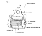
- Fig. 2 is a perspective view of the through anchor
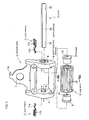
- Fig. 3 is an exploded perspective view of the through anchor
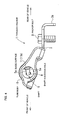
- Fig. 4 is a side view of an anchor base of the through anchor
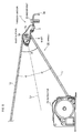
- Fig. 5 is a side view of the through anchor of an airbelt as a seat belt and the vicinity of the through anchor
- Fig. 6(a) is a side view of a leaf spring used for the through anchor
- Fig. 6(b) is a top view of the leaf spring
- Fig. 7(a) is a side view of a bearing used for the through anchor
- Fig. 1 is a perspective view showing an example of a seat belt apparatus provided with a through anchor according to an embodiment of the present invention
- Fig. 2 is a perspective view of the through anchor
- Fig. 3 is an exploded perspective view of the through anchor
- Fig. 4 is a side
- FIG. 7(b) is an end face view of the bearing (a view along arrows B-B of Fig. 7(a) ),
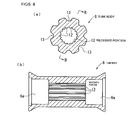
- Fig. 8(a) is a cross-section view of a tube body constituting a hanging shaft of the through anchor (a cross-section view along lines VIIIA-VIIIA of Fig. 3 ),
- Fig. 8(b) is a cross-section view along lines B-B of Fig. 8(a) ,
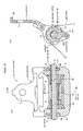
- Fig. 9(a) is a vertical cross-section view of the through anchor when not locked,
- Fig. 9(b) is a cross-section view along lines B-B of Fig. 9(a) ,
- Fig. 10(a) is a vertical cross-section view of the through anchor when locked, Fig.
- FIG. 10(b) is a cross-section view along lines B-B of Fig. 10(a)
- Fig. 11 is a cross-section view of a portion similar to that of Fig. 8(a) , showing a state in which an airbelt and a tube body are engaged with each other.
- the through anchor which is installed in a substantially vehicle fore-and-aft direction, is shown to be oriented along the up-and-down direction of the drawing in Figs. 2 , 3 and Figs. 9 , 10 .
- a through anchor 1 is installed in a vehicle in which a driver's seat and a passenger's seat are provided and no rear seat is provided, i.e., a so-called two seater-type vehicle.
- the present invention is not limited to any particular model of vehicle.
- the through anchor 1 includes a hanging shaft 2 on which a seat belt is hung, an anchor base 3 supporting the hanging shaft 2, and the like.
- the hanging shaft 2 is composed of a shaft non-rotatably mounted across a pair of shaft receiving portions 4, 4 provided to the anchor base 3, and a tube body 6 rotatably attached outside the shaft 5.
- this through anchor 1 is mounted on a behind-a-seat member M in a vehicle body so that the direction in which the shaft 5 extends becomes a substantially vehicle width direction (i.e., a substantially left and right direction).
- the anchor base 3 is disposed so that the shaft receiving portions 4, 4 are located on the vehicle front side and the opposite side thereof is located on the vehicle rear side.
- the anchor base 3 is provided with a bolt insertion hole 7 on the side opposite to the shaft receiving portions 4, 4, and the through anchor 1 is joined to the behind-a-seat member M using an anchor bolt B through the bolt insertion hole 7 so as to be pivotable in a substantially vehicle width direction.
- Reference numeral 3a denotes a lug by which the pivot angle of the anchor base 3 is restricted.
- a retractor 24 is installed on the vehicle front side relative to the through anchor 1. This retractor is located at a position lower than the through anchor 1, as shown in Fig. 5 . From the retractor 24, an airbelt 20 being a seat belt is withdrawn. This airbelt 20 is withdrawn from the retractor 24 in a vehicle rear direction, and then is hung on the tube body 6 after being passed so as to be detoured from the underside of the tube body 6 to the upperside of the tube body 6 through the back of the tube body 6 on its vehicle rear side; then the airbelt 20 is routed from the tube body 6 toward the vehicle front side.
- Fig. 5 the airbelt 20 is shown in a state of completion of wearing thereof, in which the airbelt 20 is routed on the front side of an occupant (not shown) seated on a seat Z ( Fig. 1 ) and is latched to a buckle device 27 described later.
- this bisecting line L 3 extends in a substantially vehicle fore-and-aft direction and also in a slightly downward direction toward the vehicle front side.
- the shaft 5 is a square bar-like member having a substantially rectangular cross-sectional shape in a direction intersecting its longitudinal direction in this embodiment.
- a cross section of the shaft 5 means the cross section in a direction intersecting its longitudinal direction.
- a pair of side faces extending along a longer edge direction of the cross section become guide surfaces 5a, which guide the movement of the tube body 6.
- a square bar-like shaft 5 may be constructed from plural thicknesses of a strip-like plain shaft having a thin thickness in the present invention.
- the shaft receiving portions 4, 4 are disposed apart from each other by a predetermined distance in a substantially vehicle width direction, and each of the shaft receiving portions 4, 4 is provided with a shaft insertion hole 8, which passes therethrough in a substantially vehicle width direction.
- this shaft insertion hole 8 has an opening shape of a substantially rectangle.
- the width of the shaft insertion hole 8 in its shorter edge direction is equal to or slightly larger than the width of a cross section of the shaft 5 in its shorter edge direction.
- the width of the shaft insertion hole 8 in its longer edge direction is equal to or slightly larger than the width of the sum of the width of a cross section of the shaft 5 in the longer edge direction and the thickness of a securing portion 11b of a leaf spring 11 described later.
- each of the shaft insertion holes 8 is formed so that its longer edges extend in a direction substantially parallel to the above bisecting line L 3 .
- the shaft 5 is inserted to each of the shaft insertion holes 8 so that the longer edge direction of its cross section meets the longer edge direction of the shaft insertion hole 8, and the both ends of the shaft 5 in its longitudinal direction are held non-rotatably in the shaft insertion holes 8, respectively. That is, the guide surfaces 5a of the shaft 5 extend along a direction substantially parallel to the bisecting line L 3 bisecting the intersection angle ⁇ constituted between the one extension direction L 1 in which the airbelt 20 extends on the side of the retractor 24 relative to the tube body 6 and the other extension direction L 2 in which the airbelt 20 extends on the side of an occupant relative to the tube body 6, in a state that the airbelt 20 is worn by the occupant seated on a seat, as shown in Fig. 5 .
- the intersection angle ( ⁇ /2) constituted between the bisecting line L 3 and each of the extension directions L1, L2 is preferably to be the order of 16° to 28°, specifically the order of 20°.
- a recessed portion 5b on a surface on each of both end sides of the shaft 5 in its longitudinal direction, the surface being oriented substantially to the front of the vehicle (hereafter, occasionally called the "front face"), and the shaft 5 is positioned (prevented from coming out from either of the shaft insertion holes 8) by that an edge portion substantially on the vehicle front side of each of the shaft insertion holes 8 is engaged with the recessed portion 5b.
- the inner diameter of the tube body 6 is larger than the cross- sectional width of the shaft 5 in its diagonal direction.
- the recessed portions 12 extending in the axis line direction of the tube body 6 each have a groove-like shape and are provided in plural number at an even spacing from each other in the circumferential direction of the tube body 6.
- a bearing 9 on each of the both ends of the tube body 6 in its axis line direction.
- a large diameter portion 6a is configured on the both end sides of the tube body 6, the large diameter portion 6a having an inner diameter larger than that of the middle side and being fitted with the bearing 9 therein so as to be rotatable.
- the shaft insertion hole 10 of each of the bearings 9 also has an opening shape of a substantially rectangle.
- the width of the shaft insertion hole 10 in its shorter edge direction is also equal to or slightly larger than the width of a cross section of the shaft 5 in its shorter edge direction, and the width of the shaft insertion hole 10 in its longer edge direction is larger than the width of a cross section of the shaft 5 in the longer edge direction by a predetermined width.
- the shaft 5 is inserted so that the longer edge direction of its cross section meets the longer edge direction of the shaft insertion hole 10.
- Each of the bearings 9 is thereby held non-rotatably with respect to the shaft 5, and also is supported so as to be slidable along the guide surface 5a of the shaft 5 in a direction substantially parallel to the above bisecting line L 3 .
- the tube body 6 is supported rotatably with respect to the shaft 5 and also so as to be movable along the guide surface 5a in a direction substantially parallel to the above bisecting line L 3 .
- each of the shaft insertion holes 10 is disposed so that the tube body 6 is supported substantially coaxially with respect to the shaft 5 by the respective bearings 9 in a state that the front face of the shaft 5 is in contact to the edge portion substantially on the vehicle front side (hereafter, occasionally called the "front edge") of the shaft insertion hole 10, i.e., in a state that the bearings 9 are each located at the movable limit position in a substantially vehicle rear direction.
- leaf spring 11 between the rear face of the shaft 5 and the edge portion substantially on the vehicle rear side (hereafter, occasionally called the "rear edge") of the shaft insertion hole 10 of the respective bearings 9, the leaf spring 11 applying a force to the bearing 9 in a substantially vehicle rear direction.
- the leaf springs 11 are each inserted into the shaft insertion hole 10 of the respective bearings 9 from the shaft insertion hole 8 of the respective shaft receiving portions 4 along the rear face of the shaft 5.
- the tip side of the leaf spring 11 in the insertion direction is configured to be a force applying portion 11a bent in a mountain shape toward a substantially vehicle rear direction, and this force applying portion 11a is involved between the rear face of the shaft 5 and the rear edge of the shaft insertion hole 10 of the respective bearings 9 to serve for applying a force to the respective bearings 9 toward a substantially vehicle rear direction.
- a securing portion 11b engaged to the shaft insertion hole 8 of the respective shaft receiving portions 4, and the leaf spring 11 is secured (prevented from coming out from either of the shaft insertion holes 10, 8) by that the securing portion 11b engages with the side edge of the shaft insertion hole 8.
- the leaf springs 11 are each configured so that, when a pressing force of a predetermined magnitude or more is applied to the tube body 6 from a seat belt hung on the tube body 6 toward a substantially vehicle front direction (a direction substantially parallel to the above bisecting line L 3 ), the force applying portion 11a thereof is elastically deformed so as to be flattened, and allows the bearing 9 to move along a substantially vehicle front direction, i.e., the tube body 6 to move along a substantially vehicle front direction.
- a stopping mechanism for the tube body 6 is constructed of the angular convex portions 5t of the shaft 5, the recessed portions 12 inside the tube body 6, and the leaf springs 11.
- recessed portions 13 also on the outer periphery of the tube body 6 so as to extend in the axis line direction thereof in plural number at an even spacing from each other in the circumferential direction thereof.
- the recessed portions 13 serve for receiving wrinkles arising on a curved portion of a shoulder belt portion 21 of the airbelt 20 (described later).
- the airbelt 20 having an inflatable shoulder belt portion 21 is hung on the tube body 6 of the through anchor 1.
- the airbelt 20 includes the shoulder belt portion 21, which is routed diagonally along the front side of the upper body of an occupant seated on a vehicle seat Z ( Fig. 1 ), a webbing 22, the tip of which is connected to the rear end of the shoulder belt portion 21, and a lap belt portion 23, which is routed over a near portion of the hip of the occupant in a left and right direction.
- the rear end side of the webbing 22 is joined to the retractor 24 so as to be retractable and withdrawable.
- This webbing 22 is fabricated of a non-inflatable belt material as in the case of a general seat belt.
- the shoulder belt portion 21 and the webbing 22 are hung on the tube body 6 of the through anchor 1.
- the shoulder belt portion 21 is formed in a way that a thick width belt-like bag is folded to become a thin belt-like one and is covered with a cover; in normal times, it is maintained in a belt-like shape.
- the shoulder belt portion 21 having multilayers of base cloth constituting the bag and cover like this is bent along the perimeter of the tube body 6 of the through anchor 1, one side thereof facing the tube body 6 is loosened, which causes wrinkles, as shown in Fig. 11 .
- the tip side of the shoulder belt portion 21 and the tip side of the lap belt portion 23 are each connected to a tongue 25.
- the lap belt portion 23 is also fabricated of a non-inflatable belt material as in the case of an ordinary seat belt.
- the rear end side of the lap belt portion 23 is also joined to the retractor 26 so as to be retractable and withdrawable.
- a buckle device 27 On the opposite side of the retractor 26 across the seat Z, there is provided a buckle device 27 to which the tongue 25 is latched.
- an inflator 28 is provided to the buckle device 27, the inflator 28 allowing the shoulder belt portion 21 to be inflated by supplying gas to the bag of the shoulder belt portion 21.
- the retractors 24, 26 are provided with a locking mechanism for locking withdrawal of the webbing 22 and the lap belt portion 23, respectively, in case of an emergency, such as a vehicle collision or the like, and also an EA mechanism for absorbing an impact applied to the occupant by gradually feeding the webbing 22 and the lap belt portion 23 when a load of a predetermined magnitude or more is applied to the webbing 22 and the lap belt portion 23 in this locking state, respectively.
- the locking of the retractors 24, 26 are activated to lock withdrawal of the webbing 22 and the lap belt portion 23, respectively, and the inflator 27 is also activated to inflate the airbelt 20; the occupant is received softly by the inflated airbelt 20.
- the pressing force applied to the tube body 6 from the airbelt 20 also becomes smaller than the predetermined value and then the tube body 6 is pushed back along the guide surfaces 5a in a substantially vehicle rear direction due to a force applied from the respective leaf springs 11; thereby the recessed portions 12 of the tube body 6 and the angular convex portions 5t of the shaft 5 made separated from each other and the locking of the tube body 6 is released.
- the leaf springs 11 are provided between the tube body 6 and the shaft 5, and the leaf springs 11 each apply a force to the tube body 6 so that the recessed portions 12 on the inner periphery of the tube body 6 and the angular convex portions 5t of the shaft are separated. Because of this, the whole of the tube body 6 can be constructed of hard materials, so the durability of the tube body 6 can be made favorable. Additionally, since a tube body equivalent to a general conventional one constructed from low-cost plastic or the like can be employed, it is possible to construct the through anchor 1 at relatively low cost.
- the guide surfaces 5a for guiding movement of the tube body 6, and these guide surfaces 5a extend along a direction substantially parallel to the bisecting line L 3 bisecting the intersection angle ⁇ constituted between the one extension direction L 1 in which the airbelt 20 extends on the side of the retractor 24 relative to the tube body 6 and the other extension direction L 2 in which the airbelt 20 extends on the side of an occupant relative to the tube body 6, in a state that the airbelt 20 is worn by the occupant.
- the through anchor 1 even if a pressing force of a predetermined value or more is applied to the tube body 6 from the airbelt 20 and the stopping mechanism is activated, when the pressing force having been applied to the tube body 6 from the airbelt 20 becomes smaller than the predetermined value, the tube body 6 returns to its original position due to the force applied from the respective leaf springs 11, and the tube body 6 becomes freely rotatable again; the through anchor 1 returns to its usual usage state. It is not necessary to replace the through anchor 1 every time the stopping mechanism is activated, which brings about an economical advantage.
- the present invention is not limited to any particular model of vehicle, and it is applicable, for example, to a vehicle equipped with a rear seat. It should be noted that, in the case when the present invention is applied to a seat belt apparatus for a rear seat of a vehicle, the through anchor is installed at the same installation structure as or in a similar installation structure to that for the two seater-type vehicle. Likewise, in the case when the present invention is applied to a vehicle having a pillar portion, the through anchor may be installed on the pillar portion.
- Fig. 12 is a perspective view of a seat belt apparatus, showing an arrangement in which a through anchor is attached to a pillar portion of a vehicle
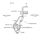
- Fig. 13 is a side view of the through anchor in the arrangement of Fig. 12 .
- a through anchor 1 is installed on a pillar portion P of a vehicle body so that the extension direction of its shaft 5 becomes a substantially vehicle fore-and-aft direction.
- An anchor base 3 of this through anchor 1 is disposed so that the side of its shaft receiving portions 4, 4 comes to the lower side and the side of its bolt insertion hole 7 comes to the upperside, and is attached rotatably to the pillar portion P using an anchor bolt B through the bolt insertion hole 7 in a substantially vehicle fore-and-aft direction.
- a retractor 24 is mounted in a position lower than the through anchor 1.
- An airbelt 20 is withdrawn upwardly from the retractor 24, and then is hung on a tube body 6 after being passed so as to be detoured from the vehicle exterior side of the tube body 6 to the vehicle interior side of the tube body 6 through the upperside of the tube body 6; then the airbelt 20 is routed downwardly forward of a seat (not shown) from the tube body 6.
- guide surfaces 5a of the shaft 5 extend in a substantially up-and-down direction and is slightly inclined to the vehicle interior side with distance to its top end.
- the guide surfaces 5a extend in a direction substantially parallel to the bisecting line bisecting the intersection angle constituted between one extension direction in which the airbelt 20 extends on the side of the retractor 24 relative to the tube body 6 and the other extension direction in which the airbelt 20 extends on the side of an occupant relative to the tube body 6, in a state that the airbelt 20 is routed on the front side of an occupant on a seat (not shown) and latched to a buckle device 27.
- the intersection angle between the bisecting line and each of the one extension direction in which the airbelt 20 extends on the side of the retractor 24 relative to the tube body 6 and the other extension direction in which the airbelt 20 extends on the side of the occupant relative to the tube body 6 is preferably to be the order of 16° to 28°, specifically the order of 20°.
- the actuation of the through anchor 1 in this embodiment is similar to that of the embodiment of Figs. 1 to 11 , except that the extension direction of the shaft 5 becomes a substantially vehicle fore-and-aft direction and the direction of pressing force applied to the tube body 6 from the airbelt 20 becomes a substantially up-and-down direction.
- the seat belt hung on the hanging shaft (tube body) of the through anchor may be not an airbelt, but a normal seat belt of a non-inflatable type.
- the grooves 13 on the outer periphery of the tube body 6 may be omitted.
Landscapes
- Engineering & Computer Science (AREA)
- Mechanical Engineering (AREA)
- Automotive Seat Belt Assembly (AREA)
- Emergency Lowering Means (AREA)
Applications Claiming Priority (1)
| Application Number | Priority Date | Filing Date | Title |
|---|---|---|---|
| JP2007258856A JP5125375B2 (ja) | 2007-10-02 | 2007-10-02 | シートベルトのスルーアンカ、シートベルト装置及び車両 |
Publications (3)
| Publication Number | Publication Date |
|---|---|
| EP2045149A2 true EP2045149A2 (fr) | 2009-04-08 |
| EP2045149A3 EP2045149A3 (fr) | 2009-11-25 |
| EP2045149B1 EP2045149B1 (fr) | 2011-02-16 |
Family
ID=39800504
Family Applications (1)
| Application Number | Title | Priority Date | Filing Date |
|---|---|---|---|
| EP08016272A Not-in-force EP2045149B1 (fr) | 2007-10-02 | 2008-09-16 | Renvoi de sangle de ceinture de sécurité, dispositif de ceinture de sécurité et véhicule équipé d'un tel dispositif |
Country Status (5)
| Country | Link |
|---|---|
| US (1) | US7748744B2 (fr) |
| EP (1) | EP2045149B1 (fr) |
| JP (1) | JP5125375B2 (fr) |
| CN (1) | CN101402346B (fr) |
| DE (1) | DE602008004962D1 (fr) |
Cited By (1)
| Publication number | Priority date | Publication date | Assignee | Title |
|---|---|---|---|---|
| DE102013205776A1 (de) * | 2013-04-02 | 2014-10-30 | Autoliv Development Ab | Umlenker für eine Sicherheitsgurteinrichtung mit einem zwei- oder mehrlagigen aufblasbaren Sicherheitsgurt |
Families Citing this family (13)
| Publication number | Priority date | Publication date | Assignee | Title |
|---|---|---|---|---|
| JP5244751B2 (ja) * | 2009-09-18 | 2013-07-24 | トヨタ自動車株式会社 | 車両用乗員拘束装置 |
| JP5529487B2 (ja) * | 2009-10-07 | 2014-06-25 | タカタ株式会社 | エアベルト装置 |
| DE102012000486A1 (de) * | 2012-01-13 | 2013-07-18 | Daimler Ag | Aufrollvorrichtung zum Aufrollen eines Gurtbandes und Sicherheitsgurtsystem |
| CN102874207A (zh) * | 2012-10-22 | 2013-01-16 | 宜兴市奥华汽配有限公司 | 一种汽车安全带单端片及其制备方法 |
| CN103253227A (zh) * | 2013-05-29 | 2013-08-21 | 宜兴市奥华汽配有限公司 | 一种方孔翻边安全带端片 |
| US9260076B2 (en) * | 2013-07-23 | 2016-02-16 | Honda Motor Co., Ltd. | Method, system and apparatus for stabilizing vehicle occupant's shoulder during side collision impact |
| CN104442682B (zh) * | 2014-11-03 | 2020-02-21 | 宁波市镇海西门专利技术开发有限公司 | 一种带扣的止带装置 |
| DE102014017788B4 (de) * | 2014-12-03 | 2020-03-26 | Trw Automotive Gmbh | Steckzunge |
| JP6325040B2 (ja) * | 2016-08-29 | 2018-05-16 | 株式会社東海理化電機製作所 | 移動装置 |
| JP2018047745A (ja) * | 2016-09-20 | 2018-03-29 | タカタ株式会社 | タング及びシートベルト装置 |
| US10793102B2 (en) * | 2018-10-12 | 2020-10-06 | Ford Global Technologies, Llc | Seat belt webbing guide |
| DE102018220620B4 (de) * | 2018-11-29 | 2022-10-13 | Joyson Safety Systems Germany Gmbh | Gurtumlenkeinrichtung |
| CN112824162A (zh) * | 2019-11-20 | 2021-05-21 | 奥托立夫开发公司 | 安全带组件 |
Family Cites Families (11)
| Publication number | Priority date | Publication date | Assignee | Title |
|---|---|---|---|---|
| US4993746A (en) * | 1989-09-05 | 1991-02-19 | Ford Motor Company | Locking frictional D-ring |
| US5415433A (en) * | 1993-07-30 | 1995-05-16 | Alliedsignal Inc. | Seat belt roller D-ring |
| DE29502192U1 (de) | 1995-02-10 | 1995-05-04 | Trw Repa Gmbh, 73553 Alfdorf | Umlenkbeschlag für Sicherheitsgurte |
| US6749225B1 (en) * | 1997-07-29 | 2004-06-15 | Autoliv Development Ab | Safety belt system with pre-tensioning device for secondary collision |
| US6250684B1 (en) * | 1998-10-01 | 2001-06-26 | Trw Vehicle Safety Systems Inc. | D-ring/roller assembly for supporting seat belt webbing in a vehicle |
| US6446897B1 (en) * | 1999-03-04 | 2002-09-10 | Nsk Ltd. | Seat belt system |
| DE19913423C1 (de) * | 1999-03-25 | 2000-05-11 | Autoliv Dev | Umlenkeinrichtung für einen Sicherheitsgurt |
| JP2001213270A (ja) * | 2000-02-04 | 2001-08-07 | Osamu Ishihara | シートべルトの巻き戻りストッパ、及び、シートべルトの巻き戻り停止方法 |
| JP4120616B2 (ja) * | 2004-04-30 | 2008-07-16 | 日産自動車株式会社 | シートベルト用ロック装置 |
| US7370822B2 (en) * | 2004-07-28 | 2008-05-13 | Takata Corporation | Seatbelt retractor having multi-level load-limit setting devices |
| JP5011779B2 (ja) | 2005-04-04 | 2012-08-29 | タカタ株式会社 | エアベルト装置 |
-
2007
- 2007-10-02 JP JP2007258856A patent/JP5125375B2/ja not_active Expired - Fee Related
-
2008
- 2008-09-16 DE DE602008004962T patent/DE602008004962D1/de active Active
- 2008-09-16 EP EP08016272A patent/EP2045149B1/fr not_active Not-in-force
- 2008-09-22 US US12/232,666 patent/US7748744B2/en not_active Expired - Fee Related
- 2008-09-28 CN CN2008101681476A patent/CN101402346B/zh not_active Expired - Fee Related
Cited By (2)
| Publication number | Priority date | Publication date | Assignee | Title |
|---|---|---|---|---|
| DE102013205776A1 (de) * | 2013-04-02 | 2014-10-30 | Autoliv Development Ab | Umlenker für eine Sicherheitsgurteinrichtung mit einem zwei- oder mehrlagigen aufblasbaren Sicherheitsgurt |
| DE102013205776B4 (de) * | 2013-04-02 | 2021-03-04 | Autoliv Development Ab | Umlenker für eine Sicherheitsgurteinrichtung mit einem zwei- oder mehrlagigen aufblasbaren Sicherheitsgurt |
Also Published As
| Publication number | Publication date |
|---|---|
| EP2045149A3 (fr) | 2009-11-25 |
| EP2045149B1 (fr) | 2011-02-16 |
| CN101402346B (zh) | 2012-08-08 |
| JP2009083779A (ja) | 2009-04-23 |
| CN101402346A (zh) | 2009-04-08 |
| US7748744B2 (en) | 2010-07-06 |
| US20090085341A1 (en) | 2009-04-02 |
| JP5125375B2 (ja) | 2013-01-23 |
| DE602008004962D1 (de) | 2011-03-31 |
Similar Documents
| Publication | Publication Date | Title |
|---|---|---|
| EP2045149B1 (fr) | Renvoi de sangle de ceinture de sécurité, dispositif de ceinture de sécurité et véhicule équipé d'un tel dispositif | |
| US9827883B2 (en) | Child seat | |
| KR101612542B1 (ko) | 개선된 설치를 위한 벨트 텐셔닝기구를 구비한 차일드시트 | |
| US20060208471A1 (en) | Inflatable seatbelt system | |
| JP5224827B2 (ja) | タングおよびこれを用いたシートベルト装置 | |
| CN102649415A (zh) | 乘员保护装置 | |
| JP5478995B2 (ja) | シートベルト装置 | |
| CN102217820B (zh) | 用于安全带的带扣 | |
| CN101578204B (zh) | 用于机动车辆的安全带系统 | |
| US7219957B1 (en) | Vehicle seat with articulating cushion component | |
| EP2818368B1 (fr) | Languette et dispositif de ceinture de sécurité l'utilisant | |
| JP2011063226A (ja) | 車両用乗員拘束装置 | |
| JP6012561B2 (ja) | シートベルトバックル装置およびシートベルト装置 | |
| JP5530148B2 (ja) | シートベルト装置 | |
| CN110843722A (zh) | 车辆座椅安全带系统 | |
| JP7254757B2 (ja) | 乗員拘束装置 | |
| JP5169673B2 (ja) | 乗員拘束具 | |
| JP4565957B2 (ja) | ウエビング挿通部材 | |
| JP2007245786A (ja) | シートベルト装置 | |
| JP4407683B2 (ja) | シートベルト装置 | |
| JP6744113B2 (ja) | 乗員保護装置 | |
| JP2013032061A (ja) | シートベルト装置 | |
| JP2007253732A (ja) | シートベルト装置 | |
| KR100616006B1 (ko) | 임산부를 위한 차량용 시트벨트 | |
| JP2011156902A (ja) | シートベルト装置 |
Legal Events
| Date | Code | Title | Description |
|---|---|---|---|
| PUAI | Public reference made under article 153(3) epc to a published international application that has entered the european phase |
Free format text: ORIGINAL CODE: 0009012 |
|
| AK | Designated contracting states |
Kind code of ref document: A2 Designated state(s): AT BE BG CH CY CZ DE DK EE ES FI FR GB GR HR HU IE IS IT LI LT LU LV MC MT NL NO PL PT RO SE SI SK TR |
|
| AX | Request for extension of the european patent |
Extension state: AL BA MK RS |
|
| PUAL | Search report despatched |
Free format text: ORIGINAL CODE: 0009013 |
|
| AK | Designated contracting states |
Kind code of ref document: A3 Designated state(s): AT BE BG CH CY CZ DE DK EE ES FI FR GB GR HR HU IE IS IT LI LT LU LV MC MT NL NO PL PT RO SE SI SK TR |
|
| AX | Request for extension of the european patent |
Extension state: AL BA MK RS |
|
| 17P | Request for examination filed |
Effective date: 20100519 |
|
| AKX | Designation fees paid |
Designated state(s): DE FR GB |
|
| RIC1 | Information provided on ipc code assigned before grant |
Ipc: B60R 22/185 20060101AFI20100625BHEP |
|
| GRAP | Despatch of communication of intention to grant a patent |
Free format text: ORIGINAL CODE: EPIDOSNIGR1 |
|
| GRAS | Grant fee paid |
Free format text: ORIGINAL CODE: EPIDOSNIGR3 |
|
| GRAA | (expected) grant |
Free format text: ORIGINAL CODE: 0009210 |
|
| AK | Designated contracting states |
Kind code of ref document: B1 Designated state(s): DE FR GB |
|
| REG | Reference to a national code |
Ref country code: GB Ref legal event code: FG4D |
|
| REF | Corresponds to: |
Ref document number: 602008004962 Country of ref document: DE Date of ref document: 20110331 Kind code of ref document: P |
|
| REG | Reference to a national code |
Ref country code: DE Ref legal event code: R096 Ref document number: 602008004962 Country of ref document: DE Effective date: 20110331 |
|
| PLBE | No opposition filed within time limit |
Free format text: ORIGINAL CODE: 0009261 |
|
| STAA | Information on the status of an ep patent application or granted ep patent |
Free format text: STATUS: NO OPPOSITION FILED WITHIN TIME LIMIT |
|
| 26N | No opposition filed |
Effective date: 20111117 |
|
| REG | Reference to a national code |
Ref country code: DE Ref legal event code: R097 Ref document number: 602008004962 Country of ref document: DE Effective date: 20111117 |
|
| REG | Reference to a national code |
Ref country code: FR Ref legal event code: ST Effective date: 20120531 |
|
| PG25 | Lapsed in a contracting state [announced via postgrant information from national office to epo] |
Ref country code: FR Free format text: LAPSE BECAUSE OF NON-PAYMENT OF DUE FEES Effective date: 20110930 |
|
| PGFP | Annual fee paid to national office [announced via postgrant information from national office to epo] |
Ref country code: GB Payment date: 20130911 Year of fee payment: 6 |
|
| GBPC | Gb: european patent ceased through non-payment of renewal fee |
Effective date: 20140916 |
|
| PG25 | Lapsed in a contracting state [announced via postgrant information from national office to epo] |
Ref country code: GB Free format text: LAPSE BECAUSE OF NON-PAYMENT OF DUE FEES Effective date: 20140916 |
|
| REG | Reference to a national code |
Ref country code: DE Ref legal event code: R082 Ref document number: 602008004962 Country of ref document: DE Representative=s name: KRAUS & WEISERT PATENTANWAELTE PARTGMBB, DE Ref country code: DE Ref legal event code: R081 Ref document number: 602008004962 Country of ref document: DE Owner name: JOYSON SAFETY SYSTEMS JAPAN K.K., JP Free format text: FORMER OWNER: TAKATA CORP., TOKIO/TOKYO, JP |
|
| PGFP | Annual fee paid to national office [announced via postgrant information from national office to epo] |
Ref country code: DE Payment date: 20190918 Year of fee payment: 12 |
|
| REG | Reference to a national code |
Ref country code: DE Ref legal event code: R119 Ref document number: 602008004962 Country of ref document: DE |
|
| PG25 | Lapsed in a contracting state [announced via postgrant information from national office to epo] |
Ref country code: DE Free format text: LAPSE BECAUSE OF NON-PAYMENT OF DUE FEES Effective date: 20210401 |