EP2045172B1 - Haubenpositionierungsstruktur für Mehrzweckfahrzeuge - Google Patents
Haubenpositionierungsstruktur für Mehrzweckfahrzeuge Download PDFInfo
- Publication number
- EP2045172B1 EP2045172B1 EP07019250A EP07019250A EP2045172B1 EP 2045172 B1 EP2045172 B1 EP 2045172B1 EP 07019250 A EP07019250 A EP 07019250A EP 07019250 A EP07019250 A EP 07019250A EP 2045172 B1 EP2045172 B1 EP 2045172B1
- Authority
- EP
- European Patent Office
- Prior art keywords
- hood
- vehicle
- crossbar
- chassis
- bracket
- Prior art date
- Legal status (The legal status is an assumption and is not a legal conclusion. Google has not performed a legal analysis and makes no representation as to the accuracy of the status listed.)
- Ceased
Links
- 230000008878 coupling Effects 0.000 claims abstract description 11
- 238000010168 coupling process Methods 0.000 claims abstract description 11
- 238000005859 coupling reaction Methods 0.000 claims abstract description 11
- 238000012423 maintenance Methods 0.000 abstract description 9
- 235000013399 edible fruits Nutrition 0.000 description 4
- 241001122767 Theaceae Species 0.000 description 2
- 238000005516 engineering process Methods 0.000 description 2
- 238000006073 displacement reaction Methods 0.000 description 1
- 238000003306 harvesting Methods 0.000 description 1
- 230000002452 interceptive effect Effects 0.000 description 1
- 230000007774 longterm Effects 0.000 description 1
- 238000000034 method Methods 0.000 description 1
- 238000012986 modification Methods 0.000 description 1
- 230000004048 modification Effects 0.000 description 1
- 239000000575 pesticide Substances 0.000 description 1
- 238000006748 scratching Methods 0.000 description 1
- 230000002393 scratching effect Effects 0.000 description 1
- 238000009331 sowing Methods 0.000 description 1
- 238000006467 substitution reaction Methods 0.000 description 1
Images





Classifications
-
- B—PERFORMING OPERATIONS; TRANSPORTING
- B62—LAND VEHICLES FOR TRAVELLING OTHERWISE THAN ON RAILS
- B62D—MOTOR VEHICLES; TRAILERS
- B62D25/00—Superstructure or monocoque structure sub-units; Parts or details thereof not otherwise provided for
- B62D25/08—Front or rear portions
- B62D25/10—Bonnets or lids, e.g. for trucks, tractors, busses, work vehicles
- B62D25/12—Parts or details thereof
-
- E—FIXED CONSTRUCTIONS
- E05—LOCKS; KEYS; WINDOW OR DOOR FITTINGS; SAFES
- E05D—HINGES OR SUSPENSION DEVICES FOR DOORS, WINDOWS OR WINGS
- E05D11/00—Additional features or accessories of hinges
- E05D11/06—Devices for limiting the opening movement of hinges
-
- E—FIXED CONSTRUCTIONS
- E05—LOCKS; KEYS; WINDOW OR DOOR FITTINGS; SAFES
- E05Y—INDEXING SCHEME ASSOCIATED WITH SUBCLASSES E05D AND E05F, RELATING TO CONSTRUCTION ELEMENTS, ELECTRIC CONTROL, POWER SUPPLY, POWER SIGNAL OR TRANSMISSION, USER INTERFACES, MOUNTING OR COUPLING, DETAILS, ACCESSORIES, AUXILIARY OPERATIONS NOT OTHERWISE PROVIDED FOR, APPLICATION THEREOF
- E05Y2900/00—Application of doors, windows, wings or fittings thereof
- E05Y2900/50—Application of doors, windows, wings or fittings thereof for vehicles
- E05Y2900/53—Type of wing
- E05Y2900/536—Hoods
Definitions
- the present invention relates to a hood positioning structure of a multi-purpose vehicle, and in particularly to a positioning structure that is coupled to a hood of a multi-purpose vehicle to ensure desired positioning of the hood when the hood is open.
- manpower has been playing an important role in carrying out agricultural operations, such as picking and culling, of for example tea leaves and fruit in the tea field or fruit field, application of pesticides, and sowing and harvest of crop fields. All of these jobs are done by manpower in the traditional society.
- various agricultural machines were created to take part of the role of manpower.
- agriculture which primitively supported the development of industry, is now getting further development with the aid of industrial technology.
- An example of the agricultural machines is a powered agricultural-purpose transportation cart. Since many fruit fields are located in mountainous area, the road or route for transportation of fruit is usually bumpy and rugged, as well as being narrow and constricted. This limits the use of regular-sized or large-sized truck, and because of the reason, specific-purpose power transportation cart or vehicle is developed for using in the mountainous area, such as the agricultural-purpose transportation cart.
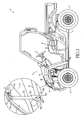
- FIGS 1 and 2 of the attached drawings illustrate an example of the conventional multi-purpose vehicle for agriculture, which is broadly designated at 1, comprising a hood 1 having an inside surface and a bracket 12 mounted to a front portion of an inside surface of the hood 11.
- the bracket 12 is pivotally connected to a chassis 14 of the vehicle 1 by a rotational shaft 13.
- the hood 11 is lifted up to open and by such a lifting operation, the hood 11 is caused to rotate about the rotational shaft 13 to thereby open the hood 11.
- a cable 15 is arranged between the hood 11 and the chassis 14 by having opposite ends of the cable 15 respectively attached to the inside surface of the hood 11 and the chassis 14.
- the cable 15 has a predetermined length that sets a limit to the rotation angle, or angular displacement, of the hood 11.
- Document US 3,487,887 describes a similar hood positioning structure.
- the cable 15 connected between the hood 11 and the chassis 14 effectively prevents over-rotation or excessive travel of the hood 11, which may cause damage to the bumper 16, the cable 15 may get slackened or loosened after long term use.
- the cable 15 is mounted to the chassis 14 and this causes, to some extents, interference with the operation of maintenance of the vehicle 1.
- the arrangement of the cable 15 occupies a great amount of space after the hood 11 is open. Besides interfering with the maintenance or repairing of the vehicle 1, such an arrangement also influence full exploitation of the space under the hood 11.
- the present invention is aimed to provide a multi-purpose vehicle 1 of the previously described type that overcomes the drawbacks.
- the primary purpose of the present invention is to provide a multi-purpose vehicle that overcomes the drawbacks of the conventional multi-purpose vehicle that uses a cable to connect a hood to a chassis of the vehicle, including slackening and loosening of the cable, interference with vehicle maintenance and repairing and preventing full use of the space under the hood.
- a multi-purpose vehicle comprising a hood positioning structure, which comprises a crossbar and two brackets.
- the crossbar has opposite ends forming connection portions and a middle section forming a fixing seat, by which connection portions and fixing seat, the crossbar is fixed to a hood of the vehicle.
- Each bracket comprises a U-shaped channel member and is coupled to an end of the crossbar respectively. A free end of the bracket forms a notch that spaces side walls of the bracket to form a coupling portion and forms a stop.
- the coupling portion is pivotally connected to the chassis to allow the hood to be lifted up for opening and the hood is positioned by the stop of the bracket abutting a predetermined portion of the chassis to thereby set the hood in a stable open position for preventing the hood from undesirably hitting a bumper of the vehicle and eliminate undesired interference with access of a space between an open hood and the chassis to ensure easy maintenance and repairing of the vehicle.
- a hood positioning structure for a multi-purpose vehicle, wherein a storage bin is arranged in the space between the hood and the chassis to fully exploit the limited available in the vehicle.
- the steering device 4 is rotatably mounted to the chassis 3.
- the front wheels 5 are arranged below the steering device 4.
- the seat 6 is mounted to the chassis 3 at a location behind the steering device 4.
- the power unit that is not shown in the drawings is arranged below the seat 6.
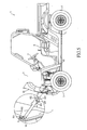
- the vehicle cover assembly 8 comprises a hood 81 that is arranged at a front portion of the vehicle 2 and side fenders 82 that are arranged below the steering device 4 and extend to opposite sides of the vehicle.
- the positioning structure 9 comprises a crossbar 91 and two bracket bars 92.
- the crossbar 91 has two opposite ends each forming a connection portion 911 and a middle section between the ends and forming a fixing seat 912 that protrudes from the middle section.
- the connection portions 911 and the fixing seat 912 are secured to the hood 81 by means of bolts S.
- the bracket bars 92 are mounted to the crossbar 91 on opposite sides of the middle section of the crossbar 91 and each bracket bar 92 is formed of an elongated channel-like member having a U-shaped cross-section defined by a bottom and two side walls extending from the bottom.
- the bottom of the U-shaped cross-section of the bracket bar 92 forms a notch 921 of a predetermined depth in the length direction of the bracket bar 92.
- the notch 921 spaces portions of the side walls of the bracket bar 92, which correspond to the notch 921 of the bottom, from each other to form a coupling portion 922 for coupling with the chassis 31.
- a bottom of the notch 921 forms a stop 923.
- the coupling portion 922 that is formed by the spaced portions of the side walls of the bracket bar 92 is pivotally connected to the chassis 31 by a pivot 924 that extends through aligned holes (not labeled) defined in the portions of the side walls corresponding to the notch 921 of the bottom.
- the coupling portions 922 of the bracket bars 92 and the pivots 924 arranged at the front portion of the chassis 31 together form a pivotal joint that provides a rotation center so that when the hood 81 is lifted up and rotated to a limit position where the stops 923 of the bracket bars 92 engage and abut against portions of the chassis 31, the maximum stroke of the hood 81 is set.
- the weight of a headlight assembly L is moved forward until the stops 923 abut against the portions of the chassis 31, where the hood 81 is kept in a force- and torque balanced condition and is thus maintained in a stable open position. Since the positioning structure 9 is set in the front portion of the chassis 31, interference similar to that associated with the conventionally used cable that was described previously will not occur so that maintenance and repairing of the vehicle 2 can be carried out without undesired interference.
- the hood positioning mechanism 9 is arranged at a front portion of t chassis 31 and is fixed to the hood 81 so that when the hood 81 is open, stops 923 formed on brackets 92 may advantageously abut against predetermined portions of the chassis 3 to ensure stable and proper positioning of the hood 81 and undesired interference with the maintenance and repairing of the vehicle 2 is eliminated. Further, the space between the hood 81 of the vehicle 2 and the chassis 31 is fully utilized by providing a storage bin A in the space and located below the hood 81 when the hood 81 is closed.
Landscapes
- Engineering & Computer Science (AREA)
- Mechanical Engineering (AREA)
- Chemical & Material Sciences (AREA)
- Combustion & Propulsion (AREA)
- Transportation (AREA)
- Body Structure For Vehicles (AREA)
- Superstructure Of Vehicle (AREA)
Claims (5)
- Eine Haubenpositionierungsstruktur (9) für ein Mehrzweckfahrzeug (2), gekennzeichnet durch eine an der Innenseite der Haube (11) des Mehrzweckfahrzeugs (2) befestigte Querstrebe (91) und an beiden Enden der Querstrebe (91) angebrachte Beschläge (92), die jeweils am freien Ende eine Aussparung (921) haben, die einen Anschlag (923) bildet, sowie abgeteilte Abschnitte der Aussparungen (921) der Beschläge (92), die einen Kupplungsabschnitt bilden, wobei durch die an der Haube (11) angebrachte Querstrebe (91) und dadurch, daß die Kupplungsabschnitte der Beschläge (92) gelenkig mit dem Fahrzeugchassis verbunden sind beim Anheben der Haube (11) entsprechende Teile am Chassis in die Anschläge (923) eingreifen und die Haube (11) in ihrer Position halten.
- Die Haubenpositionierungsstruktur aus Anspruch 1, bei der die Enden der Querstrebe (91) jeweils einen Kupplungsabschnitt (922) bilden.
- Die Haubenpositionierungsstruktur aus Anspruch 1, bei der sich im Mittelabschnitt der Querstrebe (91) ein Befestigungssitz (912) befindet.
- Die Haubenpositionierungsstruktur aus Anspruch 1, bei der jeder der Beschläge (92) einen U-förmigen Abschnitt hat.
- Die Haubenpositionierungsstruktur aus Anspruch 1, bei der zusätzlich zwischen Haube und Fahrzeugchassis ein Staubehälter angebracht ist.
Priority Applications (3)
| Application Number | Priority Date | Filing Date | Title |
|---|---|---|---|
| AT07019250T ATE453559T1 (de) | 2007-10-01 | 2007-10-01 | Haubenpositionierungsstruktur für mehrzweckfahrzeuge |
| EP07019250A EP2045172B1 (de) | 2007-10-01 | 2007-10-01 | Haubenpositionierungsstruktur für Mehrzweckfahrzeuge |
| DE602007004117T DE602007004117D1 (de) | 2007-10-01 | 2007-10-01 | Haubenpositionierungsstruktur für Mehrzweckfahrzeuge |
Applications Claiming Priority (1)
| Application Number | Priority Date | Filing Date | Title |
|---|---|---|---|
| EP07019250A EP2045172B1 (de) | 2007-10-01 | 2007-10-01 | Haubenpositionierungsstruktur für Mehrzweckfahrzeuge |
Publications (2)
| Publication Number | Publication Date |
|---|---|
| EP2045172A1 EP2045172A1 (de) | 2009-04-08 |
| EP2045172B1 true EP2045172B1 (de) | 2009-12-30 |
Family
ID=39049678
Family Applications (1)
| Application Number | Title | Priority Date | Filing Date |
|---|---|---|---|
| EP07019250A Ceased EP2045172B1 (de) | 2007-10-01 | 2007-10-01 | Haubenpositionierungsstruktur für Mehrzweckfahrzeuge |
Country Status (3)
| Country | Link |
|---|---|
| EP (1) | EP2045172B1 (de) |
| AT (1) | ATE453559T1 (de) |
| DE (1) | DE602007004117D1 (de) |
Family Cites Families (4)
| Publication number | Priority date | Publication date | Assignee | Title |
|---|---|---|---|---|
| US3487887A (en) * | 1966-10-08 | 1970-01-06 | Massey Ferguson Services Nv | Closure for vehicle compartments |
| JPH0396487A (ja) * | 1989-09-08 | 1991-04-22 | Iseki & Co Ltd | トラクターのボンネット開閉装置 |
| US5136752A (en) * | 1991-06-26 | 1992-08-11 | Deere & Company | Hinge and latch structure for vehicle hood |
| US6003204A (en) * | 1998-07-27 | 1999-12-21 | Deere & Company | Hood hinge mechanism |
-
2007
- 2007-10-01 DE DE602007004117T patent/DE602007004117D1/de active Active
- 2007-10-01 AT AT07019250T patent/ATE453559T1/de not_active IP Right Cessation
- 2007-10-01 EP EP07019250A patent/EP2045172B1/de not_active Ceased
Also Published As
| Publication number | Publication date |
|---|---|
| EP2045172A1 (de) | 2009-04-08 |
| ATE453559T1 (de) | 2010-01-15 |
| DE602007004117D1 (de) | 2010-02-11 |
Similar Documents
| Publication | Publication Date | Title |
|---|---|---|
| US7926249B1 (en) | Transport system for a harvest header | |
| US5544944A (en) | Adjustable utility trailer | |
| US8789646B2 (en) | Steering apparatus of for a tractor | |
| US7188857B2 (en) | Transformable utility/ATV trailer | |
| EP3025946B1 (de) | Faltbares fahrrad | |
| US20090084619A1 (en) | Hood positioning structure of multi-purpose vehicle | |
| US20060086008A1 (en) | Mounting of an accessory on an ATV | |
| US6692014B1 (en) | Load hauling trailer assembly adapted for on and off road use | |
| US7036618B2 (en) | Hood assembly | |
| US7850184B1 (en) | Cargo trailer | |
| US7448691B2 (en) | Mower payload bin | |
| EP2045172A1 (de) | Haubenpositionierungsstruktur für Mehrzweckfahrzeuge | |
| US8528800B1 (en) | Support structure for a spare tire carrier assembly | |
| KR102239092B1 (ko) | 사륜 독립구동 전동운반차 | |
| CA2534200A1 (en) | Self contained transport for crop harvesting header | |
| CN211571824U (zh) | 一种兼容工程机械属具与农用机械属具的多功能工程车 | |
| US7552933B1 (en) | Cargo trailer | |
| NL1037078C2 (nl) | Landbouwmachine. | |
| US20130189066A1 (en) | Tractor | |
| US7618050B2 (en) | Vehicle steering arrangements | |
| US7490799B2 (en) | Multi-position support for PTO drive | |
| US20080315556A1 (en) | Tractor hitch attachment connector | |
| US5967532A (en) | Towable auger carrier for snow machines | |
| US20080052968A1 (en) | Plow system for non-highway vehicles | |
| US12178154B2 (en) | Method and apparatus for mounting a flail mower |
Legal Events
| Date | Code | Title | Description |
|---|---|---|---|
| PUAI | Public reference made under article 153(3) epc to a published international application that has entered the european phase |
Free format text: ORIGINAL CODE: 0009012 |
|
| AK | Designated contracting states |
Kind code of ref document: A1 Designated state(s): AT BE BG CH CY CZ DE DK EE ES FI FR GB GR HU IE IS IT LI LT LU LV MC MT NL PL PT RO SE SI SK TR |
|
| AX | Request for extension of the european patent |
Extension state: AL BA HR MK RS |
|
| 17P | Request for examination filed |
Effective date: 20090409 |
|
| GRAP | Despatch of communication of intention to grant a patent |
Free format text: ORIGINAL CODE: EPIDOSNIGR1 |
|
| GRAS | Grant fee paid |
Free format text: ORIGINAL CODE: EPIDOSNIGR3 |
|
| GRAA | (expected) grant |
Free format text: ORIGINAL CODE: 0009210 |
|
| AKX | Designation fees paid |
Designated state(s): AT BE BG CH CY CZ DE DK EE ES FI FR GB GR HU IE IS IT LI LT LU LV MC MT NL PL PT RO SE SI SK TR |
|
| AK | Designated contracting states |
Kind code of ref document: B1 Designated state(s): AT BE BG CH CY CZ DE DK EE ES FI FR GB GR HU IE IS IT LI LT LU LV MC MT NL PL PT RO SE SI SK TR |
|
| REG | Reference to a national code |
Ref country code: GB Ref legal event code: FG4D |
|
| REG | Reference to a national code |
Ref country code: CH Ref legal event code: EP |
|
| REG | Reference to a national code |
Ref country code: IE Ref legal event code: FG4D |
|
| REF | Corresponds to: |
Ref document number: 602007004117 Country of ref document: DE Date of ref document: 20100211 Kind code of ref document: P |
|
| PG25 | Lapsed in a contracting state [announced via postgrant information from national office to epo] |
Ref country code: LT Free format text: LAPSE BECAUSE OF FAILURE TO SUBMIT A TRANSLATION OF THE DESCRIPTION OR TO PAY THE FEE WITHIN THE PRESCRIBED TIME-LIMIT Effective date: 20091230 Ref country code: FI Free format text: LAPSE BECAUSE OF FAILURE TO SUBMIT A TRANSLATION OF THE DESCRIPTION OR TO PAY THE FEE WITHIN THE PRESCRIBED TIME-LIMIT Effective date: 20091230 Ref country code: SE Free format text: LAPSE BECAUSE OF FAILURE TO SUBMIT A TRANSLATION OF THE DESCRIPTION OR TO PAY THE FEE WITHIN THE PRESCRIBED TIME-LIMIT Effective date: 20091230 |
|
| REG | Reference to a national code |
Ref country code: NL Ref legal event code: VDEP Effective date: 20091230 |
|
| LTIE | Lt: invalidation of european patent or patent extension |
Effective date: 20091230 |
|
| PG25 | Lapsed in a contracting state [announced via postgrant information from national office to epo] |
Ref country code: PL Free format text: LAPSE BECAUSE OF FAILURE TO SUBMIT A TRANSLATION OF THE DESCRIPTION OR TO PAY THE FEE WITHIN THE PRESCRIBED TIME-LIMIT Effective date: 20091230 Ref country code: SI Free format text: LAPSE BECAUSE OF FAILURE TO SUBMIT A TRANSLATION OF THE DESCRIPTION OR TO PAY THE FEE WITHIN THE PRESCRIBED TIME-LIMIT Effective date: 20091230 Ref country code: LV Free format text: LAPSE BECAUSE OF FAILURE TO SUBMIT A TRANSLATION OF THE DESCRIPTION OR TO PAY THE FEE WITHIN THE PRESCRIBED TIME-LIMIT Effective date: 20091230 |
|
| PG25 | Lapsed in a contracting state [announced via postgrant information from national office to epo] |
Ref country code: AT Free format text: LAPSE BECAUSE OF FAILURE TO SUBMIT A TRANSLATION OF THE DESCRIPTION OR TO PAY THE FEE WITHIN THE PRESCRIBED TIME-LIMIT Effective date: 20091230 |
|
| PG25 | Lapsed in a contracting state [announced via postgrant information from national office to epo] |
Ref country code: IS Free format text: LAPSE BECAUSE OF FAILURE TO SUBMIT A TRANSLATION OF THE DESCRIPTION OR TO PAY THE FEE WITHIN THE PRESCRIBED TIME-LIMIT Effective date: 20100430 Ref country code: NL Free format text: LAPSE BECAUSE OF FAILURE TO SUBMIT A TRANSLATION OF THE DESCRIPTION OR TO PAY THE FEE WITHIN THE PRESCRIBED TIME-LIMIT Effective date: 20091230 Ref country code: PT Free format text: LAPSE BECAUSE OF FAILURE TO SUBMIT A TRANSLATION OF THE DESCRIPTION OR TO PAY THE FEE WITHIN THE PRESCRIBED TIME-LIMIT Effective date: 20100430 Ref country code: ES Free format text: LAPSE BECAUSE OF FAILURE TO SUBMIT A TRANSLATION OF THE DESCRIPTION OR TO PAY THE FEE WITHIN THE PRESCRIBED TIME-LIMIT Effective date: 20100410 Ref country code: EE Free format text: LAPSE BECAUSE OF FAILURE TO SUBMIT A TRANSLATION OF THE DESCRIPTION OR TO PAY THE FEE WITHIN THE PRESCRIBED TIME-LIMIT Effective date: 20091230 Ref country code: BG Free format text: LAPSE BECAUSE OF FAILURE TO SUBMIT A TRANSLATION OF THE DESCRIPTION OR TO PAY THE FEE WITHIN THE PRESCRIBED TIME-LIMIT Effective date: 20100330 Ref country code: RO Free format text: LAPSE BECAUSE OF FAILURE TO SUBMIT A TRANSLATION OF THE DESCRIPTION OR TO PAY THE FEE WITHIN THE PRESCRIBED TIME-LIMIT Effective date: 20091230 |
|
| PG25 | Lapsed in a contracting state [announced via postgrant information from national office to epo] |
Ref country code: SK Free format text: LAPSE BECAUSE OF FAILURE TO SUBMIT A TRANSLATION OF THE DESCRIPTION OR TO PAY THE FEE WITHIN THE PRESCRIBED TIME-LIMIT Effective date: 20091230 Ref country code: CZ Free format text: LAPSE BECAUSE OF FAILURE TO SUBMIT A TRANSLATION OF THE DESCRIPTION OR TO PAY THE FEE WITHIN THE PRESCRIBED TIME-LIMIT Effective date: 20091230 Ref country code: BE Free format text: LAPSE BECAUSE OF FAILURE TO SUBMIT A TRANSLATION OF THE DESCRIPTION OR TO PAY THE FEE WITHIN THE PRESCRIBED TIME-LIMIT Effective date: 20091230 |
|
| PG25 | Lapsed in a contracting state [announced via postgrant information from national office to epo] |
Ref country code: CY Free format text: LAPSE BECAUSE OF FAILURE TO SUBMIT A TRANSLATION OF THE DESCRIPTION OR TO PAY THE FEE WITHIN THE PRESCRIBED TIME-LIMIT Effective date: 20091230 Ref country code: GR Free format text: LAPSE BECAUSE OF FAILURE TO SUBMIT A TRANSLATION OF THE DESCRIPTION OR TO PAY THE FEE WITHIN THE PRESCRIBED TIME-LIMIT Effective date: 20100331 |
|
| PLBE | No opposition filed within time limit |
Free format text: ORIGINAL CODE: 0009261 |
|
| STAA | Information on the status of an ep patent application or granted ep patent |
Free format text: STATUS: NO OPPOSITION FILED WITHIN TIME LIMIT |
|
| 26N | No opposition filed |
Effective date: 20101001 |
|
| PG25 | Lapsed in a contracting state [announced via postgrant information from national office to epo] |
Ref country code: DK Free format text: LAPSE BECAUSE OF FAILURE TO SUBMIT A TRANSLATION OF THE DESCRIPTION OR TO PAY THE FEE WITHIN THE PRESCRIBED TIME-LIMIT Effective date: 20091230 |
|
| PG25 | Lapsed in a contracting state [announced via postgrant information from national office to epo] |
Ref country code: IT Free format text: LAPSE BECAUSE OF FAILURE TO SUBMIT A TRANSLATION OF THE DESCRIPTION OR TO PAY THE FEE WITHIN THE PRESCRIBED TIME-LIMIT Effective date: 20091230 |
|
| PG25 | Lapsed in a contracting state [announced via postgrant information from national office to epo] |
Ref country code: MC Free format text: LAPSE BECAUSE OF NON-PAYMENT OF DUE FEES Effective date: 20101031 |
|
| PG25 | Lapsed in a contracting state [announced via postgrant information from national office to epo] |
Ref country code: IE Free format text: LAPSE BECAUSE OF NON-PAYMENT OF DUE FEES Effective date: 20101001 |
|
| PG25 | Lapsed in a contracting state [announced via postgrant information from national office to epo] |
Ref country code: MT Free format text: LAPSE BECAUSE OF FAILURE TO SUBMIT A TRANSLATION OF THE DESCRIPTION OR TO PAY THE FEE WITHIN THE PRESCRIBED TIME-LIMIT Effective date: 20091230 |
|
| REG | Reference to a national code |
Ref country code: CH Ref legal event code: PL |
|
| GBPC | Gb: european patent ceased through non-payment of renewal fee |
Effective date: 20111001 |
|
| PG25 | Lapsed in a contracting state [announced via postgrant information from national office to epo] |
Ref country code: LI Free format text: LAPSE BECAUSE OF NON-PAYMENT OF DUE FEES Effective date: 20111031 Ref country code: CH Free format text: LAPSE BECAUSE OF NON-PAYMENT OF DUE FEES Effective date: 20111031 |
|
| PG25 | Lapsed in a contracting state [announced via postgrant information from national office to epo] |
Ref country code: GB Free format text: LAPSE BECAUSE OF NON-PAYMENT OF DUE FEES Effective date: 20111001 |
|
| PG25 | Lapsed in a contracting state [announced via postgrant information from national office to epo] |
Ref country code: HU Free format text: LAPSE BECAUSE OF FAILURE TO SUBMIT A TRANSLATION OF THE DESCRIPTION OR TO PAY THE FEE WITHIN THE PRESCRIBED TIME-LIMIT Effective date: 20100701 Ref country code: LU Free format text: LAPSE BECAUSE OF NON-PAYMENT OF DUE FEES Effective date: 20101001 |
|
| PG25 | Lapsed in a contracting state [announced via postgrant information from national office to epo] |
Ref country code: TR Free format text: LAPSE BECAUSE OF FAILURE TO SUBMIT A TRANSLATION OF THE DESCRIPTION OR TO PAY THE FEE WITHIN THE PRESCRIBED TIME-LIMIT Effective date: 20091230 |
|
| REG | Reference to a national code |
Ref country code: FR Ref legal event code: PLFP Year of fee payment: 9 |
|
| REG | Reference to a national code |
Ref country code: FR Ref legal event code: PLFP Year of fee payment: 10 |
|
| REG | Reference to a national code |
Ref country code: FR Ref legal event code: PLFP Year of fee payment: 11 |
|
| REG | Reference to a national code |
Ref country code: FR Ref legal event code: PLFP Year of fee payment: 12 |
|
| PGFP | Annual fee paid to national office [announced via postgrant information from national office to epo] |
Ref country code: DE Payment date: 20190821 Year of fee payment: 13 |
|
| PGFP | Annual fee paid to national office [announced via postgrant information from national office to epo] |
Ref country code: FR Payment date: 20191028 Year of fee payment: 13 |
|
| REG | Reference to a national code |
Ref country code: DE Ref legal event code: R119 Ref document number: 602007004117 Country of ref document: DE |
|
| PG25 | Lapsed in a contracting state [announced via postgrant information from national office to epo] |
Ref country code: DE Free format text: LAPSE BECAUSE OF NON-PAYMENT OF DUE FEES Effective date: 20210501 Ref country code: FR Free format text: LAPSE BECAUSE OF NON-PAYMENT OF DUE FEES Effective date: 20201031 |