EP2045481A2 - Dispositif d'actionnement pour un embrayage de véhicule - Google Patents
Dispositif d'actionnement pour un embrayage de véhicule Download PDFInfo
- Publication number
- EP2045481A2 EP2045481A2 EP08163367A EP08163367A EP2045481A2 EP 2045481 A2 EP2045481 A2 EP 2045481A2 EP 08163367 A EP08163367 A EP 08163367A EP 08163367 A EP08163367 A EP 08163367A EP 2045481 A2 EP2045481 A2 EP 2045481A2
- Authority
- EP
- European Patent Office
- Prior art keywords
- connection
- cylinder
- actuating device
- pressure medium
- connection plate
- Prior art date
- Legal status (The legal status is an assumption and is not a legal conclusion. Google has not performed a legal analysis and makes no representation as to the accuracy of the status listed.)
- Granted
Links
- 230000008878 coupling Effects 0.000 title 1
- 238000010168 coupling process Methods 0.000 title 1
- 238000005859 coupling reaction Methods 0.000 title 1
- 238000001125 extrusion Methods 0.000 abstract 1
- 230000005540 biological transmission Effects 0.000 description 3
- 238000004519 manufacturing process Methods 0.000 description 2
- 238000005516 engineering process Methods 0.000 description 1
- 238000000034 method Methods 0.000 description 1
- 238000004080 punching Methods 0.000 description 1
- 238000007789 sealing Methods 0.000 description 1
Images
Classifications
-
- F—MECHANICAL ENGINEERING; LIGHTING; HEATING; WEAPONS; BLASTING
- F16—ENGINEERING ELEMENTS AND UNITS; GENERAL MEASURES FOR PRODUCING AND MAINTAINING EFFECTIVE FUNCTIONING OF MACHINES OR INSTALLATIONS; THERMAL INSULATION IN GENERAL
- F16D—COUPLINGS FOR TRANSMITTING ROTATION; CLUTCHES; BRAKES
- F16D25/00—Fluid-actuated clutches
- F16D25/08—Fluid-actuated clutches with fluid-actuated member not rotating with a clutching member
- F16D25/082—Fluid-actuated clutches with fluid-actuated member not rotating with a clutching member the line of action of the fluid-actuated members co-inciding with the axis of rotation
- F16D25/083—Actuators therefor
-
- F—MECHANICAL ENGINEERING; LIGHTING; HEATING; WEAPONS; BLASTING
- F16—ENGINEERING ELEMENTS AND UNITS; GENERAL MEASURES FOR PRODUCING AND MAINTAINING EFFECTIVE FUNCTIONING OF MACHINES OR INSTALLATIONS; THERMAL INSULATION IN GENERAL
- F16D—COUPLINGS FOR TRANSMITTING ROTATION; CLUTCHES; BRAKES
- F16D25/00—Fluid-actuated clutches
- F16D25/08—Fluid-actuated clutches with fluid-actuated member not rotating with a clutching member
- F16D25/082—Fluid-actuated clutches with fluid-actuated member not rotating with a clutching member the line of action of the fluid-actuated members co-inciding with the axis of rotation
- F16D25/087—Fluid-actuated clutches with fluid-actuated member not rotating with a clutching member the line of action of the fluid-actuated members co-inciding with the axis of rotation the clutch being actuated by the fluid-actuated member via a diaphragm spring or an equivalent array of levers
Definitions
- the DE 103 49 171 A1 describes an actuating device for a vehicle clutch, in which a working space in a cylinder can be filled arbitrarily via a pressure medium connection.
- the cylinder has a connection opening in a floor.
- the connection opening in the floor is in register with a recess in a connection plate, by means of which the actuating device is fixed in the drive train.
- the DE 103 49 171 A1 contains no information on how the print medium transfer is carried out exactly.
- the object of the present invention is to provide a simple and space-saving connection technology for a pressure medium connection in the bottom region of a cylinder of the actuating device.
- connection plate carries a connection element for a fastening means which fixes a pressure medium connection to the actuating device.
- the great advantage of the invention is that the cylinder does not have to contain openings for a fastener and accordingly the risk of leakage is very small.
- connection element is designed as a threaded sleeve.
- the threaded sleeve is designed as a necking of the connection plate.
- the connection plate no welds or similar elaborate fastening techniques must be made.
- the necking can already proceed as a processing step when punching out the connection plate.
- connection plate has at least one opening through which at least one support element of the pressure medium connection engages on the bottom of the cylinder.
- the support element is designed sickle-shaped to provide an accurate alignment. Furthermore, the surface load on the bottom of the cylinder is minimized.
- the pressure medium connection has a screw flange, in which fastening sleeves are fixed, which have the support elements.
- a plastic could be used, since the mounting sleeves absorb the biasing forces of the fasteners.
- the fastening sleeve has an axial securing, which is chambered axially between the bottom of the cylinder and the connecting plate.
- the fastening sleeve can be produced as a separate component for the cylinder or the retaining plate.
- connection plate or the bottom has a pocket for receiving the axial securing of the fastening sleeve.
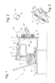
- the FIG. 1 shows a sectional view through an actuator 1 for a friction clutch.
- the actuator comprises a with a pressure medium, for.
- a pressure medium for.
- a gas or a hydraulic medium randomly supplied cylinder 3 in which a piston 5 in response to the level of the pressure medium in a work space formed by the piston and the cylinder 7 exerts an axial operating movement on a transmission element of the friction clutch, not shown in this Case of a diaphragm spring 9, an opening force exerts.
- the cylinder is fixedly connected to a connection plate 11 and secured via this fixed to a coaxial transmission shaft, not shown, to a transmission housing.
- the diaphragm spring because it is connected via a clutch housing to the crankshaft of an engine, always rotates at the crankshaft speed.
- a bearing 13 is arranged between the diaphragm spring and the piston, which is formed by a roller bearing with an inner bearing ring 15 and an outer bearing ring 17, which can rotate in the circumferential direction relative to each other.
- the outer bearing ring is pressed by a biasing spring 19 against the piston.
- the inner bearing is located on the diaphragm spring. Due to this arrangement, a limited offset between the diaphragm spring and the piston can be compensated by a self-centering.
- the working space 7 is supplied via a pressure medium connection 21, which is fixed on an outer side of a bottom 23 of the cylinder.
- a connection opening 25 is executed, which coincides with a connection channel 27 the pressure medium connection 21 is.
- the pressure medium connection 21 has a screw flange 29 in which metallic fastening sleeves 31 are fixed.
- the fastening sleeves, Fig. 2 crescent-shaped support elements 33, which also engage through crescent-shaped openings 35 in the connection plate 11, Fig. 3 , and supported directly on the outside of the bottom 23.
- a centering opening 37 for the mounting flange 29 including at least one seal 39 is present.
- the fastening flange 29 is fixed to the connecting plate 11 by screws 41 which run in the fastening sleeves.
- the connection plate 11 carries a connection element in the form of a threaded sleeve 43 into which the screws 41 engage.
- the threaded sleeves 43 are manufactured as a necking of the connection plate 11.
- connection opening is introduced into the bottom 23 of the cylinder 3.
- the connection plate is with all openings 35; 37 manufactured, with the Aushalsungen 43 facing away from the bottom 23 in the direction.
- the pressure medium connection is fitted with the seal 39 and pressed into the centering opening, the pressure medium connection 27 retains this position and can be pressure-tightly pre-stressed via the screws 41 engaging in the threaded sleeves 43.
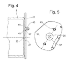
- FIG. 4 An alternative variant after Fig. 4 is characterized in that the threaded sleeve 43 is designed as a connection plate 11 and the cylinder 3 independent component, which is chambered axially via an axial securing in the form of a collar 45 between the bottom of the cylinder and the connecting plate 11.
- the connection plate 11 In the connection plate corresponding through holes 47 for the threaded sleeves 43 executed, Fig. 5 , In the area of the passage openings 47, the connection plate 11 in each case has a pocket 49 which serves to receive the collar of the threaded sleeve 43.
- the bag can also be embossed in the bottom 23 of the cylinder.
- connection plate 11 made with all openings and pockets is equipped with the threaded sleeves 43. Subsequently, one fixes the connection plate on the cylinder 3, wherein the collar 45 has each threaded sleeve in the direction of the bottom 23. Thereafter, a pressure medium connection according to the Fig. 1 placed on the connection plate 11.
- the threaded sleeve 43 engage in the mounting sleeves 31 and take the mounting screws 41.
- the passage opening 47 is designed as a polygon, in which the corresponding shaped threaded sleeve engages positively, so that co-rotation of the threaded sleeve 43 can be excluded when a fastening screws 41 are screwed.
Landscapes
- Engineering & Computer Science (AREA)
- General Engineering & Computer Science (AREA)
- Mechanical Engineering (AREA)
- Hydraulic Clutches, Magnetic Clutches, Fluid Clutches, And Fluid Joints (AREA)
Applications Claiming Priority (1)
| Application Number | Priority Date | Filing Date | Title |
|---|---|---|---|
| DE102007047514A DE102007047514A1 (de) | 2007-10-04 | 2007-10-04 | Betätigungseinrichtung für eine Fahrzeugkupplung |
Publications (3)
| Publication Number | Publication Date |
|---|---|
| EP2045481A2 true EP2045481A2 (fr) | 2009-04-08 |
| EP2045481A3 EP2045481A3 (fr) | 2010-02-17 |
| EP2045481B1 EP2045481B1 (fr) | 2011-11-09 |
Family
ID=40227769
Family Applications (1)
| Application Number | Title | Priority Date | Filing Date |
|---|---|---|---|
| EP08163367A Not-in-force EP2045481B1 (fr) | 2007-10-04 | 2008-09-01 | Dispositif d'actionnement pour un embrayage de véhicule |
Country Status (3)
| Country | Link |
|---|---|
| EP (1) | EP2045481B1 (fr) |
| AT (1) | ATE532982T1 (fr) |
| DE (1) | DE102007047514A1 (fr) |
Families Citing this family (2)
| Publication number | Priority date | Publication date | Assignee | Title |
|---|---|---|---|---|
| DE102021109034A1 (de) | 2021-04-12 | 2022-10-13 | Schaeffler Technologies AG & Co. KG | Zentralausrückeranordnung und Hybridmodul |
| DE102022133448B4 (de) * | 2022-12-15 | 2024-07-18 | Schaeffler Technologies AG & Co. KG | Nehmerzylinder mit vormontierter Dichtscheibe |
Citations (1)
| Publication number | Priority date | Publication date | Assignee | Title |
|---|---|---|---|---|
| DE10349171A1 (de) | 2003-10-22 | 2005-05-19 | Zf Friedrichshafen Ag | Betätigungseinrichtung für eine Reibungskupplung |
Family Cites Families (7)
| Publication number | Priority date | Publication date | Assignee | Title |
|---|---|---|---|---|
| DE4243170C2 (de) * | 1992-12-19 | 1997-06-12 | Daimler Benz Ag | Ausrückeinrichtung für eine Fahrzeugkupplung |
| DE4412734A1 (de) * | 1993-09-14 | 1995-03-16 | Daikin Mfg Co Ltd | Ringförmige hydraulische Kupplungsausrückzylinder-Vorrichtung |
| US5779280A (en) * | 1997-02-28 | 1998-07-14 | Mark Iv Automotive Aktiebolag | Fluid connector |
| DE102004032038A1 (de) * | 2003-07-24 | 2005-02-10 | Zf Sachs Ag | Betätigungseinrichtung für eine Kupplung |
| US7028822B2 (en) * | 2003-08-13 | 2006-04-18 | North American Clutch Corporation | Integrated actuator assembly |
| DE102004049804A1 (de) * | 2004-10-12 | 2006-04-20 | Benteler Automobiltechnik Gmbh | Common-Rail |
| BRPI0708526A8 (pt) * | 2006-03-06 | 2016-12-27 | Luk Lamellen & Kupplungsbau | Dispositivo para o acionamento de uma embreagem |
-
2007
- 2007-10-04 DE DE102007047514A patent/DE102007047514A1/de not_active Ceased
-
2008
- 2008-09-01 EP EP08163367A patent/EP2045481B1/fr not_active Not-in-force
- 2008-09-01 AT AT08163367T patent/ATE532982T1/de active
Patent Citations (1)
| Publication number | Priority date | Publication date | Assignee | Title |
|---|---|---|---|---|
| DE10349171A1 (de) | 2003-10-22 | 2005-05-19 | Zf Friedrichshafen Ag | Betätigungseinrichtung für eine Reibungskupplung |
Also Published As
| Publication number | Publication date |
|---|---|
| EP2045481A3 (fr) | 2010-02-17 |
| ATE532982T1 (de) | 2011-11-15 |
| EP2045481B1 (fr) | 2011-11-09 |
| DE102007047514A1 (de) | 2009-04-09 |
Similar Documents
| Publication | Publication Date | Title |
|---|---|---|
| DE102015215447A1 (de) | Antriebsmodul für einen Antriebsstrang eines Hybridfahrzeugs | |
| DE102017104446A1 (de) | Mehrfachkupplungseinrichtung und Hybridmodul für ein Kraftfahrzeug | |
| DE112007003348B4 (de) | Kompressor mit einer Federdruck-Lamellenkupplung | |
| WO2003100260A2 (fr) | Systeme hydraulique, en particulier pour vehicules a moteur | |
| WO2009037176A2 (fr) | Passage tournant pour l'alimentation en huile d'un arbre de transmission présentant un alésage s'étendant axialement ou un passage d'huile | |
| EP2045481B1 (fr) | Dispositif d'actionnement pour un embrayage de véhicule | |
| DE102019133966A1 (de) | Elektromotorisch angetriebener hydraulischer Pumpenaktor | |
| DE112011101630B4 (de) | Zentralausrücker zur Betätigung einer Reibungskupplung | |
| DE10008606B4 (de) | Kraftübertragungsmechanismus mit einem Sprengring zu dessen Montage | |
| EP1913288B1 (fr) | Transmission de vehicules automobiles | |
| EP1929154B1 (fr) | Pompe a piston | |
| EP1884677B1 (fr) | Dispositif d'embrayage, en particulier dispositif d'embrayage pour véhicule automobile | |
| DE102013209995A1 (de) | Kupplungsanordnung, insbesondere für eine Reibungskupplung in einem Kupplungsausrücksystem eines Kraftfahrzeuges | |
| DE102013211647A1 (de) | Innenzahnradpumpe | |
| DE112005002911B4 (de) | Pumpe | |
| EP1895185B1 (fr) | Elément de séparation, en particulier pour un élément amortisseur d'un ressort pneumatique | |
| DE102016215211A1 (de) | Radialkolbenmaschine mit Lamellenbremse | |
| WO2020192819A1 (fr) | Pompe à engrenages extérieurs | |
| DE102006011802B4 (de) | Kupplungseinheit für eine Druckmaschine | |
| DE102012220342A1 (de) | Dichtungselement für Druckfluidbetätigungseinrichtung | |
| DE102011107493A1 (de) | Riemenscheibenbaugruppe | |
| DE102018108394A1 (de) | Kupplungsanordnung mit Lagerung innerhalb einer Betätigungsvorrichtung; sowie Antriebseinheit | |
| DE102018105963A1 (de) | Hydraulische Ausrücklageranordnung | |
| DE102014001674B4 (de) | Verfahren zum Montieren einer Brennkraftmaschine sowie entsprechende Brennkraftmaschine | |
| EP1659308B1 (fr) | Dispositif d'embrayage pour l'accouplement d'un dispositif auxiliiaire |
Legal Events
| Date | Code | Title | Description |
|---|---|---|---|
| PUAI | Public reference made under article 153(3) epc to a published international application that has entered the european phase |
Free format text: ORIGINAL CODE: 0009012 |
|
| AK | Designated contracting states |
Kind code of ref document: A2 Designated state(s): AT BE BG CH CY CZ DE DK EE ES FI FR GB GR HR HU IE IS IT LI LT LU LV MC MT NL NO PL PT RO SE SI SK TR |
|
| AX | Request for extension of the european patent |
Extension state: AL BA MK RS |
|
| PUAL | Search report despatched |
Free format text: ORIGINAL CODE: 0009013 |
|
| AK | Designated contracting states |
Kind code of ref document: A3 Designated state(s): AT BE BG CH CY CZ DE DK EE ES FI FR GB GR HR HU IE IS IT LI LT LU LV MC MT NL NO PL PT RO SE SI SK TR |
|
| AX | Request for extension of the european patent |
Extension state: AL BA MK RS |
|
| RIC1 | Information provided on ipc code assigned before grant |
Ipc: F16D 25/08 20060101AFI20090119BHEP |
|
| 17P | Request for examination filed |
Effective date: 20100708 |
|
| 17Q | First examination report despatched |
Effective date: 20100803 |
|
| AKX | Designation fees paid |
Designated state(s): AT BE BG CH CY CZ DE DK EE ES FI FR GB GR HR HU IE IS IT LI LT LU LV MC MT NL NO PL PT RO SE SI SK TR |
|
| GRAP | Despatch of communication of intention to grant a patent |
Free format text: ORIGINAL CODE: EPIDOSNIGR1 |
|
| RIC1 | Information provided on ipc code assigned before grant |
Ipc: F16D 25/08 20060101AFI20110413BHEP |
|
| GRAS | Grant fee paid |
Free format text: ORIGINAL CODE: EPIDOSNIGR3 |
|
| GRAA | (expected) grant |
Free format text: ORIGINAL CODE: 0009210 |
|
| AK | Designated contracting states |
Kind code of ref document: B1 Designated state(s): AT BE BG CH CY CZ DE DK EE ES FI FR GB GR HR HU IE IS IT LI LT LU LV MC MT NL NO PL PT RO SE SI SK TR |
|
| REG | Reference to a national code |
Ref country code: GB Ref legal event code: FG4D Free format text: NOT ENGLISH |
|
| REG | Reference to a national code |
Ref country code: CH Ref legal event code: EP |
|
| REG | Reference to a national code |
Ref country code: IE Ref legal event code: FG4D Free format text: LANGUAGE OF EP DOCUMENT: GERMAN |
|
| REG | Reference to a national code |
Ref country code: DE Ref legal event code: R096 Ref document number: 502008005518 Country of ref document: DE Effective date: 20120202 |
|
| REG | Reference to a national code |
Ref country code: NL Ref legal event code: VDEP Effective date: 20111109 |
|
| LTIE | Lt: invalidation of european patent or patent extension |
Effective date: 20111109 |
|
| PG25 | Lapsed in a contracting state [announced via postgrant information from national office to epo] |
Ref country code: NO Free format text: LAPSE BECAUSE OF FAILURE TO SUBMIT A TRANSLATION OF THE DESCRIPTION OR TO PAY THE FEE WITHIN THE PRESCRIBED TIME-LIMIT Effective date: 20120209 Ref country code: IS Free format text: LAPSE BECAUSE OF FAILURE TO SUBMIT A TRANSLATION OF THE DESCRIPTION OR TO PAY THE FEE WITHIN THE PRESCRIBED TIME-LIMIT Effective date: 20120309 Ref country code: LT Free format text: LAPSE BECAUSE OF FAILURE TO SUBMIT A TRANSLATION OF THE DESCRIPTION OR TO PAY THE FEE WITHIN THE PRESCRIBED TIME-LIMIT Effective date: 20111109 |
|
| PG25 | Lapsed in a contracting state [announced via postgrant information from national office to epo] |
Ref country code: NL Free format text: LAPSE BECAUSE OF FAILURE TO SUBMIT A TRANSLATION OF THE DESCRIPTION OR TO PAY THE FEE WITHIN THE PRESCRIBED TIME-LIMIT Effective date: 20111109 Ref country code: LV Free format text: LAPSE BECAUSE OF FAILURE TO SUBMIT A TRANSLATION OF THE DESCRIPTION OR TO PAY THE FEE WITHIN THE PRESCRIBED TIME-LIMIT Effective date: 20111109 Ref country code: HR Free format text: LAPSE BECAUSE OF FAILURE TO SUBMIT A TRANSLATION OF THE DESCRIPTION OR TO PAY THE FEE WITHIN THE PRESCRIBED TIME-LIMIT Effective date: 20111109 Ref country code: GR Free format text: LAPSE BECAUSE OF FAILURE TO SUBMIT A TRANSLATION OF THE DESCRIPTION OR TO PAY THE FEE WITHIN THE PRESCRIBED TIME-LIMIT Effective date: 20120210 Ref country code: PL Free format text: LAPSE BECAUSE OF FAILURE TO SUBMIT A TRANSLATION OF THE DESCRIPTION OR TO PAY THE FEE WITHIN THE PRESCRIBED TIME-LIMIT Effective date: 20111109 Ref country code: PT Free format text: LAPSE BECAUSE OF FAILURE TO SUBMIT A TRANSLATION OF THE DESCRIPTION OR TO PAY THE FEE WITHIN THE PRESCRIBED TIME-LIMIT Effective date: 20120309 Ref country code: SI Free format text: LAPSE BECAUSE OF FAILURE TO SUBMIT A TRANSLATION OF THE DESCRIPTION OR TO PAY THE FEE WITHIN THE PRESCRIBED TIME-LIMIT Effective date: 20111109 Ref country code: SE Free format text: LAPSE BECAUSE OF FAILURE TO SUBMIT A TRANSLATION OF THE DESCRIPTION OR TO PAY THE FEE WITHIN THE PRESCRIBED TIME-LIMIT Effective date: 20111109 |
|
| REG | Reference to a national code |
Ref country code: IE Ref legal event code: FD4D |
|
| PG25 | Lapsed in a contracting state [announced via postgrant information from national office to epo] |
Ref country code: CY Free format text: LAPSE BECAUSE OF FAILURE TO SUBMIT A TRANSLATION OF THE DESCRIPTION OR TO PAY THE FEE WITHIN THE PRESCRIBED TIME-LIMIT Effective date: 20111109 |
|
| PG25 | Lapsed in a contracting state [announced via postgrant information from national office to epo] |
Ref country code: DK Free format text: LAPSE BECAUSE OF FAILURE TO SUBMIT A TRANSLATION OF THE DESCRIPTION OR TO PAY THE FEE WITHIN THE PRESCRIBED TIME-LIMIT Effective date: 20111109 Ref country code: BG Free format text: LAPSE BECAUSE OF FAILURE TO SUBMIT A TRANSLATION OF THE DESCRIPTION OR TO PAY THE FEE WITHIN THE PRESCRIBED TIME-LIMIT Effective date: 20120209 Ref country code: SK Free format text: LAPSE BECAUSE OF FAILURE TO SUBMIT A TRANSLATION OF THE DESCRIPTION OR TO PAY THE FEE WITHIN THE PRESCRIBED TIME-LIMIT Effective date: 20111109 Ref country code: CZ Free format text: LAPSE BECAUSE OF FAILURE TO SUBMIT A TRANSLATION OF THE DESCRIPTION OR TO PAY THE FEE WITHIN THE PRESCRIBED TIME-LIMIT Effective date: 20111109 Ref country code: EE Free format text: LAPSE BECAUSE OF FAILURE TO SUBMIT A TRANSLATION OF THE DESCRIPTION OR TO PAY THE FEE WITHIN THE PRESCRIBED TIME-LIMIT Effective date: 20111109 Ref country code: IE Free format text: LAPSE BECAUSE OF FAILURE TO SUBMIT A TRANSLATION OF THE DESCRIPTION OR TO PAY THE FEE WITHIN THE PRESCRIBED TIME-LIMIT Effective date: 20111109 |
|
| PG25 | Lapsed in a contracting state [announced via postgrant information from national office to epo] |
Ref country code: RO Free format text: LAPSE BECAUSE OF FAILURE TO SUBMIT A TRANSLATION OF THE DESCRIPTION OR TO PAY THE FEE WITHIN THE PRESCRIBED TIME-LIMIT Effective date: 20111109 Ref country code: IT Free format text: LAPSE BECAUSE OF FAILURE TO SUBMIT A TRANSLATION OF THE DESCRIPTION OR TO PAY THE FEE WITHIN THE PRESCRIBED TIME-LIMIT Effective date: 20111109 |
|
| PLBE | No opposition filed within time limit |
Free format text: ORIGINAL CODE: 0009261 |
|
| STAA | Information on the status of an ep patent application or granted ep patent |
Free format text: STATUS: NO OPPOSITION FILED WITHIN TIME LIMIT |
|
| 26N | No opposition filed |
Effective date: 20120810 |
|
| REG | Reference to a national code |
Ref country code: DE Ref legal event code: R097 Ref document number: 502008005518 Country of ref document: DE Effective date: 20120810 |
|
| BERE | Be: lapsed |
Owner name: ZF FRIEDRICHSHAFEN A.G. Effective date: 20120930 |
|
| PG25 | Lapsed in a contracting state [announced via postgrant information from national office to epo] |
Ref country code: MC Free format text: LAPSE BECAUSE OF NON-PAYMENT OF DUE FEES Effective date: 20120930 Ref country code: ES Free format text: LAPSE BECAUSE OF FAILURE TO SUBMIT A TRANSLATION OF THE DESCRIPTION OR TO PAY THE FEE WITHIN THE PRESCRIBED TIME-LIMIT Effective date: 20120220 |
|
| REG | Reference to a national code |
Ref country code: CH Ref legal event code: PL |
|
| GBPC | Gb: european patent ceased through non-payment of renewal fee |
Effective date: 20120901 |
|
| PG25 | Lapsed in a contracting state [announced via postgrant information from national office to epo] |
Ref country code: FI Free format text: LAPSE BECAUSE OF FAILURE TO SUBMIT A TRANSLATION OF THE DESCRIPTION OR TO PAY THE FEE WITHIN THE PRESCRIBED TIME-LIMIT Effective date: 20111109 |
|
| REG | Reference to a national code |
Ref country code: FR Ref legal event code: ST Effective date: 20130531 |
|
| PG25 | Lapsed in a contracting state [announced via postgrant information from national office to epo] |
Ref country code: CH Free format text: LAPSE BECAUSE OF NON-PAYMENT OF DUE FEES Effective date: 20120930 Ref country code: LI Free format text: LAPSE BECAUSE OF NON-PAYMENT OF DUE FEES Effective date: 20120930 Ref country code: GB Free format text: LAPSE BECAUSE OF NON-PAYMENT OF DUE FEES Effective date: 20120901 Ref country code: BE Free format text: LAPSE BECAUSE OF NON-PAYMENT OF DUE FEES Effective date: 20120930 |
|
| PG25 | Lapsed in a contracting state [announced via postgrant information from national office to epo] |
Ref country code: FR Free format text: LAPSE BECAUSE OF NON-PAYMENT OF DUE FEES Effective date: 20121001 |
|
| PG25 | Lapsed in a contracting state [announced via postgrant information from national office to epo] |
Ref country code: MT Free format text: LAPSE BECAUSE OF FAILURE TO SUBMIT A TRANSLATION OF THE DESCRIPTION OR TO PAY THE FEE WITHIN THE PRESCRIBED TIME-LIMIT Effective date: 20111109 |
|
| PG25 | Lapsed in a contracting state [announced via postgrant information from national office to epo] |
Ref country code: TR Free format text: LAPSE BECAUSE OF FAILURE TO SUBMIT A TRANSLATION OF THE DESCRIPTION OR TO PAY THE FEE WITHIN THE PRESCRIBED TIME-LIMIT Effective date: 20111109 |
|
| PG25 | Lapsed in a contracting state [announced via postgrant information from national office to epo] |
Ref country code: LU Free format text: LAPSE BECAUSE OF NON-PAYMENT OF DUE FEES Effective date: 20120901 |
|
| PG25 | Lapsed in a contracting state [announced via postgrant information from national office to epo] |
Ref country code: HU Free format text: LAPSE BECAUSE OF FAILURE TO SUBMIT A TRANSLATION OF THE DESCRIPTION OR TO PAY THE FEE WITHIN THE PRESCRIBED TIME-LIMIT Effective date: 20080901 |
|
| PGFP | Annual fee paid to national office [announced via postgrant information from national office to epo] |
Ref country code: DE Payment date: 20140827 Year of fee payment: 7 |
|
| REG | Reference to a national code |
Ref country code: AT Ref legal event code: MM01 Ref document number: 532982 Country of ref document: AT Kind code of ref document: T Effective date: 20130901 |
|
| PG25 | Lapsed in a contracting state [announced via postgrant information from national office to epo] |
Ref country code: AT Free format text: LAPSE BECAUSE OF NON-PAYMENT OF DUE FEES Effective date: 20130901 |
|
| REG | Reference to a national code |
Ref country code: DE Ref legal event code: R119 Ref document number: 502008005518 Country of ref document: DE |
|
| PG25 | Lapsed in a contracting state [announced via postgrant information from national office to epo] |
Ref country code: DE Free format text: LAPSE BECAUSE OF NON-PAYMENT OF DUE FEES Effective date: 20160401 |