EP2045523B1 - Nachverbrennungs-Brenner für Erdgas und niederkalorische Gase mit hoher Effizienz und geringen Stickstoffoxidemissionen - Google Patents
Nachverbrennungs-Brenner für Erdgas und niederkalorische Gase mit hoher Effizienz und geringen Stickstoffoxidemissionen Download PDFInfo
- Publication number
- EP2045523B1 EP2045523B1 EP07425613.2A EP07425613A EP2045523B1 EP 2045523 B1 EP2045523 B1 EP 2045523B1 EP 07425613 A EP07425613 A EP 07425613A EP 2045523 B1 EP2045523 B1 EP 2045523B1
- Authority
- EP
- European Patent Office
- Prior art keywords
- burner
- fuel gas
- delivery pipe
- unit according
- wall
- Prior art date
- Legal status (The legal status is an assumption and is not a legal conclusion. Google has not performed a legal analysis and makes no representation as to the accuracy of the status listed.)
- Not-in-force
Links
Images



Classifications
-
- F—MECHANICAL ENGINEERING; LIGHTING; HEATING; WEAPONS; BLASTING
- F23—COMBUSTION APPARATUS; COMBUSTION PROCESSES
- F23D—BURNERS
- F23D14/00—Burners for combustion of a gas, e.g. of a gas stored under pressure as a liquid
- F23D14/20—Non-premix gas burners, i.e. in which gaseous fuel is mixed with combustion air on arrival at the combustion zone
Definitions
- the present invention relates to a post-firing burner suitable for in-line installation in the feed duct of a heat recovery steam generator.
- fuels for energy-related purposes, they can also be used to raise the temperature of effluent gases with a residual oxidising potential coming from other processes, such as the exhaust gases from a gas turbine that are normally heated immediately before they enter a heat recovery steam generator. This is done to obtain a better performance of the steam generator and/or to balance any reduction in the capacity the gas turbine due to high ambient temperatures typical of the summer season, which determines a reduction in the flow rate of the available steam.
- thermodynamic cycle Combined cycles are consequently used in power plants, i.e. in order to achieve a highly efficient thermodynamic cycle, the above-described gas cycle is used in association with the retrieval of the heat contained in the exhaust fumes by means of a "heat recovery steam generator” that processes a steam cycle.
- a steam cycle downstream of the gas cycle often also provides the opportunity to increment the power output and the efficiency of the steam generator by increasing the heat content of the effluent gases from the gas turbine by means of post-firing systems capable of using the same process exhaust as the combustion agent, either as is or, in some cases, suitably corrected. These systems can sometimes double the steam generator's output.
- the known post-firing systems comprise one or more grids of post-firing burners that are normally installed inside the exhaust gas duct; in some cases, they may also be installed in a bypass duct.
- the burner is essentially a streamlined component capable of assuring the flame the necessary turbulence where, in given conditions of temperature, pressure and oxygen content in the combustion agent, the flame might be susceptible to severe instability phenomena. Given the particular features of the application, moreover, conditions of flame stability must be assured over a wide range of load variations.
- the single post-firing burners are usually installed in line, one after the other, forming rows (arrays) of burners that pass right through the effluent duct, with the same cross-section and with reduced boundary effects.
- the burner is consequently modular in terms of both the length of the single row and of the repeatability of the numerous rows needed to cover the full cross-section of the duct and thus form a "grid" of post-firing burners. Thanks to their characteristic linear arrangement, their fuel rating is usually characterized by a factor Ps that defines the heat rating of the burner per unit length.
- the post-firing burner has undergone modifications relating not only to the primary need to guarantee a stable flame over a wide range of operating conditions, but also - like all new-generation burners - with a view to containing its environmental impact and particularly to reduce the NOx emissions.
- Many combustion techniques have been applied, but the more in-depth studies have demonstrated that a stable flame can be guaranteed, ensuring a low output of NOx and CO at the same time, by partially pre-mixing the fuel with the combustion agent. This ensures a more limited formation of thermal NOx (the main path of NOx formation) and, at the same time, a valid containment of the unburnt CO.
- premixing in-line burners such as those described in US 5131836 , US 4869665 and JP 59219612 .
- a post-firing system serving processes using heat (e.g. production plants with thermal processes, such as for clinker baking or in the production of silicon): the gases used for the industrial process can be drawn more conveniently from the exhaust of engines used to generate electrical energy (e.g. a gas turbine), if a post-firing system is inserted to raise the temperature of the gas to the required level.
- heat e.g. production plants with thermal processes, such as for clinker baking or in the production of silicon
- the gases used for the industrial process can be drawn more conveniently from the exhaust of engines used to generate electrical energy (e.g. a gas turbine), if a post-firing system is inserted to raise the temperature of the gas to the required level.
- Post-firing burners, and flame stabilisers in particular are generally manufactured from castings and are consequently characterized by relatively large thicknesses ( ⁇ 10-20 mm). This technical solution is adopted to guarantee the body of the burner an adequate mechanical resistance to high temperatures. In fact, especially when the flow rate of the fuel is low, the flame is very close to the burner and temperatures even in excess of 1300 K may consequently be reached at the burner walls. Clearly, the problem of the nearness of the flame to the combustor is felt even more in the premix type configurations.
- Deflectors are often used to compensate for the limited crosswise dimensions of conventional burners. These deflectors are streamlined components that, as explained in the following paragraphs, are placed between adjacent rows of burners with a view to inducing a local pressure drop in the flow of combustion agent in the vicinity of the flame stabilisers of the adjacent burners, thus enabling the proper operation of the burners.
- US3649211 discloses a burner for placement in a gas stream with a low oxygen content, said burner having a fuel ejecting means disposed in the gas stream and adapted to direct the fuel in the downstream direction; adjacent the burner is placed an air duct to supply the burner with sufficient oxygen and permit ignition of the fuel.
- US3732059 discloses a burner for promoting the combustion of a gaseous fuel in an oxidizing atmosphere which contains oxygen in an amount less than that of air and which atmosphere has appreciable and significant flow velocity, said burner comprising one or more baffle arrays mounted across the flow of said oxidizing atmosphere.
- the general object of the present invention is to provide a post-firing burner suitable for in-line installation in a feed duct serving a heat recovery steam generator, and for combined cycle systems in particular, with a structural design that enables an effective thermal protection of the burner body while maintaining the position of the flame virtually unchanged, irrespective of the flow rate of the fuel being processed, and anchored to streamlined elements of regular shape.
- This makes it possible to use sheet metal even in thicknesses below 2 mm to make the main parts of the burner, while preserving their geometrical features in the long term.
- a particular object of the present invention is to provide a post-firing burner of the above-mentioned type wherein, thanks to the choice of a limited thickness for the main burner parts, said component parts can be manufactured by means of bending processes instead of having to use pieces obtained from castings.
- Another object of the present invention is to provide a post-firing burner of the above-mentioned type wherein an increase in the crosswise dimensions of the burners enables an improvement to be achieved in the homogeneity of the fumes downstream from the burner thanks to an increase in the quantity of combustion agent involved in the recirculation regions.
- Further object of the present invention is to provide a post-firing burner of the above-mentioned type that also guarantees the conditions needed to enable the fuel and the combustion agent to be mixed adequately so as to achieve a reduction in the emissions of unburnt gases and also of thermal NOx thanks to the consequent attenuation of the temperature peaks.
- Still another object of the present invention is to provide a post-firing burner of the above-mentioned type that enables an effective use of gaseous fuels of different types and that are difficult to burn.
- the burner also comprises:
- the burner is streamlined so as to generate a first premixing step through the interaction of the first fuel gas flow deflector means with the second deflector means, that is capable of making the oxidising gas and the burnt gases recirculate.
- This first stage takes place inside the body of the burner and enables stable flames to be generated in the various burner operating conditions.
- This stage is followed by a second stage in which the oxiding gas or combustion agent and the premixed fuel gas are mixed.
- the second stage takes place outside the body of the burner and produces a flame tending to be compact and characterized by a perfect mixing of the gases, low nitrogen oxides and carbon oxide emissions, a very wide operating range, in terms of both thermal load and chemical composition of the combustion agent, and an effective thermal protection due to a film cooling effect.
- the first deflector means comprise a front conveying wall fixed tangentially to the delivery pipe in line with the row of injector nozzles. Corresponding holes enabling the passage of the fuel gas are formed on the front wall. Parallel to said wall, a deflector plate is attached to the delivery pipe, the plate being spaced from the wall so as to define a duct running substantially orthogonal to the axis of the burner and being suitable for carrying the fuel gas towards two first mixing regions situated in symmetrically opposite positions on either side of said axis, where the premixing of the fuel gas with the oxidising gas takes place.
- the second deflector means comprise a semi cylindrical screen substantially coaxial to the delivery pipe positioned on the side diametrically opposite the front fuel gas conveying wall.
- a pair of parallel plates extending from the axial sides of said screen are fixed to two sides of the front wall that are symmetrically opposite one another on either side of the axis of the burner.
- the front sides of the two plates are fitted with respective stabiliser wings so that they define a passage between the wings and the respective plates designed to divide the flow of oxidising gas in two fractions that flow, in substantially opposite radial directions, one towards the inside of the burner and the other towards the outside and downstream of the burner.
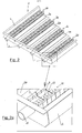
- the numeral 1 indicates a feed duct of a heat recovery steam generator (not shown) and 2 indicates an array of identical post-firing burners installed in the duct 1, through which there is a flow F of gas coming from the exhaust of a gas turbine (not shown) and moving towards the inlet of the heat recovery steam generator.
- the array 2 comprises a number of rows of in-line burners, 3a, 3b, 3c, 3d, each row being fed by a respective fuel gas delivery pipe 4.
- Figures 1 and 2 show four rows of burners simply as an example.
- the array 2 of post-firing burners comprises a frame 5, the shape of which is suitably adapted to the shape of the duct carrying the gases and the purpose of which is to support the row of burners.
- the frame is shown rectangular in shape.
- deflector elements 5a suitably shaped and positioned so as to create a significant local pressure drop and direct the flow of exhaust gases coming from the gas turbine towards the single rows of burners.
- the deflectors 5a usually consist of V-shaped plates with their tips pointing upstream with respect to the direction of the flow of oxidising gas and with said plates extending over the entire width of the frame 5.
- each fuel gas delivery pipe 4 passes right through the array 2 and serves an entire row of burners, and a row of fuel gas injector nozzles 6 is distributed along the axis of the delivery pipe 4 and oriented downstream with respect to the direction of the flow F of oxidising gas.
- the burner according to the invention comprises a front conveying wall 7 perpendicular to the flow direction F and attached to the pipe 4 by means of screws 8.
- the wall 7 is situated in front of the row of injector nozzles 6 so that it lies substantially tangent to the pipe 4 along said row.
- the wall 7 also has an intermediate channel 7a running parallel to the axis of the pipe 4 and formed with holes 9 axially aligned with the nozzles 6 to allow for the passage of the fuel gas.
- the plate 10 In front of the front wall 7 and injector nozzles 6, there is a deflector plate 10 spaced from the wall 7 such that together they define a duct 11 extending in a direction substantially orthogonal to the direction in which the fuel gas is injected through the nozzles 6.
- the plate 10 thus serves the purpose of diverting the jets of fuel gas coming through the nozzles 6 at an angle of 90° with respect to the outflow direction of said gas.
- the plate 10 has an intermediate recess 10a with a profile substantially equal to that of the intermediate channel 7a in the wall 7 so that together they define a duct portion 11a, in correspondence with the nozzles 6, that slopes in the direction in which the fuel gas flows in order to make the change of direction of the gas flow less abrupt.
- the plate 10 is attached to the fuel gas delivery pipe 4 by means of the same screws 8.
- the gap between the wall 7 and the plate 10 is assured by spacer bushes 12 attached to the wall 7 in line with through holes 13 for the screws 8.
- the plate 10 is made to abut against the bushes 12 and against the shoulders 17, provided between the wall 7 and the plate 10 to close the sides of the duct 11.
- the fuel gas delivery pipe 4 is contained in a casing, generally indicated at 14, that is lapped by the oxidising gas and is formed by a substantially semi cylindrical screen 15, coaxial to the pipe 4 and arranged on the side diametrically opposite the front fuel gas conveying wall 7, and by a pair of parallel plates 16 extending from the axial sides of the screen 15, and in particular tangentially to the cylindrical surface.
- the two plates 16 are fixed to the two symmetrically opposite sides of the wall 7 and to the shoulders 17.
- Stabiliser wings 18 are provided on the front sides of the two plates 16.
- the wings 18 are anchored isostatically to the respective plates 16 to allow for thermal expansion.
- a passage 19 for the oxidising gas is also provided, as shown in figure 5 .
- the oxidising gas laps against the casing 14 and flows against the wings 18, and is divided into two flows F1 and F2 flowing in substantially opposite radial directions and directed respectively towards the inside of the burner and the plate 10, i.e. towards the axis of the burner (coinciding with the axes of the injector nozzles 6), and towards the outside of the burner on the downstream side.
- the wings 18 can consist of flat or curved plates or, more in general, of any profile suitable for ensuring that a portion of the flow of oxidising gas be directed towards the axis of the burner.
- the distribution of the flow can be controlled by suitably inclining the wings 18 with respect to the plates 16.
- the jet of fuel gas emerges from the burner in a direction lying crosswise to the burner's axis, through the duct 11 formed between the wall 7 and the deflector plate 10 in front of the wall, before the holes 9 and the corresponding nozzles 6 through which the fuel gas comes out from the delivery pipe 4.
- the plate 10 may be of various shapes, providing it serves the purpose of diverting the fuel gas in a direction crosswise to its axis. Said gas flow laps all over the flame side of the burner (i.e. the wall 7, the plate 10 and the plate 16), consequently exerting a film cooling effect on these components.
- the jet of gas also supports the formation of the swirls in the previously-mentioned regions P, which are consequently intensified in a manner proportional to the heat rating and which are responsible for the partial premixing of the combustion agent and the fuel gas required by the process.
- an area of local recirculation is created (turning anticlockwise above the axis X-X and clockwise below said axis) that guarantees a stable flame in any operating conditions.
- the flame produced is anchored to the wings, which represent its hot point, and the consequent thermal load on the wings is balanced by the heat extraction by the flow of gas that laps over them on the inside (cooling effect by impingement).
- the main flame of the burner has two symmetrical origins starting from the two lateral hot points represented by the two stabiliser wings 18 placed symmetrically on either side of the axis of the burner.
- the thermal protection afforded in this way affects the whole burner unit, with the exception of the deflector plate 10 (which is cooled on the inside, by impingement, by the jet of cold fuel gas) and the stabiliser wings 18 (which are also cooled by impingement on the inside), as explained later on.
- This thermal protection enables the component parts of the burner to be made of sheet metal bent by plastic deformation, so the design and manufacture of the burner's components can be rapidly adapted to the various potential applications, since there is no longer any need to construct dies in which to cast them.
- the resulting burner is extremely lightweight and scarcely susceptible to temperature gradients inside the metal, or any consequent strain and cracking.
- the burner can thus be made in much larger dimensions than is the case when the components have to be obtained by casting, consequently enabling a reduction in the dimensions of the other parts involved in the assembly, e.g. the deflectors 5a used to produce the pressure drop required.
- the smooth distribution of the fuel gas is assured mainly by the shape of the deflector plate 10, and its position inside the burner. This aspect contributes to a reduction in the temperature peaks and consequently in the emission of pollutants (CO and NOx).
- the fuel gas is premixed very efficiently thanks to the formation of the two symmetrical swirls P revolving in opposite directions (see figure 5 ) supported by the jets of fuel gas and combustion agent, and contained between the two parallel plates 16, i.e. in the lower pressure zone created due to the effect of the volume of the burner inside the duct.
- the characteristics of this low pressure zone are suitably modified by the flow of the fuel gas that modulates the burner's capacity to feed a flow of combustion agent for premixing depending on the power involved, and consequently on the fuel's flow rate and velocity.
- the local pressure drop increases with the increase in the flow rate or velocity of the fuel gas.
- the burner achieves the particular feature that it can guarantee a wide range of adjustment because any increase in the flow rate of the fuel delivered corresponds to an increase in the flow rate of the combustion agent for premixing.
- the burner according to the invention has the particular feature of synergically exploiting the pressure and velocity gradients of both the oxidising fluid and the fuel gas.
- the streamlining of the burner enables an efficient burning of different types of fuel gas, however difficult they may be.
- the limited availability of a fluid dynamic load in line with the burner is put to maximum advantage exploiting the majority of the natural swirls that form and containing as far as possible the losses that are not useful for the purposes of the aerodynamics essential to the process.
- the pollutants emission such as NOx and CO emissions, is kept to negligible levels in a range of rating variation in excess of 1:10.
Landscapes
- Engineering & Computer Science (AREA)
- Chemical & Material Sciences (AREA)
- Combustion & Propulsion (AREA)
- Mechanical Engineering (AREA)
- General Engineering & Computer Science (AREA)
Claims (11)
- Nachverbrennung-Brennereinheit, die enthält:- wenigstens ein Brenngas-Zuführrohr (4), das quer zur Strömung (F) von Oxidationsgas in einer Versorgungsleitung (1) eines Dampfgenerators zur Wärmerückgewinnung liegt,- wenigstens eine Reihe von Brenngas-Einspritzdüsen (6), die längs des Zuführrohrs (4) ausgebildet ist, wobei die Achse der Düsen der Achse (X) des Brenners entspricht,- erste Brenngas-Ablenkeinrichtungen (7, 10) zum Ablenken der Brenngasströmung, die von den Düsen (6) kommt,- zweite Oxidationsgas-Ablenkeinrichtungen (14, 18), die sich um einen Teil des Zuführrohrs (4) herum erstrecken und an symmetrisch entgegengesetzten Enden der ersten Ablenkeinrichtungen (7, 10) enden,wobei der Brenner dadurch gekennzeichnet ist, dass:- die ersten Ablenkeinrichtungen (7, 10) die Brenngasströmung, die von den Düsen (6) kommt, in eine Richtung im Wesentlichen orthogonal zu der Brennerachse (X) ablenken und an dem Brenngas-Zuführrohr (4) vor den Einspritzdüsen (6) angebracht sind,- die zweiten Ablenkeinrichtungen (14, 18) ausgestaltet sind, um die Strömung des Oxidationsgases in eine erste Fraktion (F1) zur Vermischung mit der Brenngasströmung, die von den ersten Ablenkeinrichtungen (7, 10) kommt, in wenigstens einer ersten Vermischungsregion (P) innerhalb des Brenners, wo eine vorgemischte Strömung von Brenngas und Oxidationsgas gebildet wird, und eine zweite Fraktion (F2) zur Vermischung mit der vorgemischten Strömung in wenigstens einer zweiten Vermischungsregion (C) stromabwärts des Brenners teilt.
- Brennereinheit nach Anspruch 1, wobei die ersten Ablenkeinrichtungen eine vordere Leitungswand (7), die tangential an dem Zuführrohr (4) vor der Reihe von Einspritzdüsen (6) angebracht ist, wobei entsprechende Löcher in der Wand ausgebildet sind, um den Durchgang des Brenngases zu gestatten, und eine Ablenkplatte (10) enthalten, die an dem Zuführrohr (4) parallel zu der Wand (7) angebracht ist und davon beabstandet ist, um eine Leitung (11) im Wesentlichen orthogonal zu der Brennerachse (X) zu definieren, um das Brenngas zu zwei ersten Vermischungsregionen (P) zu fördern, die an symmetrisch entgegengesetzten Positionen bezüglich der Brennerachse (X) liegen.
- Brennereinheit nach Anspruch 1 oder 2, wobei ein Zwischenkanal (7a) an der Wand (7) vor der Reihe von Einspritzdüsen (6) ausgebildet ist, wobei der Kanal geneigte Wände hat und parallel zu dem Zuführrohr (4) ist, wobei eine Riffelung (10a) von komplementärer Form an der Ablenkplatte (10) ausgebildet ist, um einen geneigten Teil (11a) der Leitung (11) zu bilden.
- Brennereinheit nach einem der vorhergehenden Ansprüche, wobei Abstandhaltereinrichtungen (12) zwischen der Wand (7) und der Ablenkplatte (10) eingesetzt sind.
- Brennereinheit nach Anspruch 4, wobei die Abstandhaltereinrichtungen Buchsen (12) enthalten, die koaxial zu den Löchern (9) zwischen der Wand (7) und der Platte (10) installiert sind.
- Brennereinheit nach einem der vorhergehenden Ansprüche, wobei die zweiten Ablenkeinrichtungen eine halbzylindrische Abschirmung (15) enthalten, die im Wesentlichen koaxial zu dem Zuführrohr (4) ist und an der Seite diametral entgegengesetzt zu der vorderen Brenngas-Leitungswand (7) angeordnet ist, wobei ein Paar von parallelen Platten (16) vorgesehen ist, die sich von den axialen Seiten der Abschirmung (15) aus erstrecken und an Seiten der Wand (7) angebracht sind, die symmetrisch entgegengesetzt zueinander bezüglich der Brennerachse (X) sind, wobei entsprechende Stabilisierflügel (18) an den vorderen Seiten der zwei Platten (16) angebracht sind, wobei eine Passage (19) zwischen den Flügeln (18) und den entsprechenden Platten (16) ausgebildet sind, um in die zwei Fraktionen (F1, F2) die Strömung des Oxidationsgases zu verteilen, die in radialen Richtungen im Wesentlichen entgegengesetzt zueinander strömen, eine zur Innenseite des Brenners hin und eine zur Außenseite des Brenners hin stromabwärts davon.
- Brennereinheit nach Anspruch 6, wobei die Stabilisierflügel (18) bezüglich den parallelen Platten (16) geneigt sind.
- Brennereinheit nach einem der vorhergehenden Ansprüche, wobei seien Bestandteile aus gebogenem Blech hergestellt sind.
- Brennereinheit nach einem der vorhergehenden Ansprüche, wobei das wenigstens eine Brenngas-Zuführrohr (4) an einem Rahmen (5) installiert ist, der quer innerhalb der Oxidationsgas-Versorgungsleitung (1) liegt.
- Brennereinheit nach einem der vorhergehenden Ansprüche, dadurch gekennzeichnet, dass das wenigstens eine Brenngas-Zuführrohr (4) Brenngas zu einer Reihe anderer identischer Brenner liefert, die längs einer Achse des Rohrs (4) ausgerichtet sind, wobei der Rahmen (5) mehrere Brenngas-Zuführrohre (4) und entsprechende Reihen (3a, 3b, 3c, 3d) von parallelen Brennern trägt, die zusammen eine Anordnung (2) von Brennern bilden.
- Brennereinheit nach Anspruch 6, wobei Fluiddynamik-Ablenkelemente (5a) zwischen den Reihen (3a, 3b, 3c, 3d) von Brennern installiert sind.
Priority Applications (1)
| Application Number | Priority Date | Filing Date | Title |
|---|---|---|---|
| EP07425613.2A EP2045523B1 (de) | 2007-10-02 | 2007-10-02 | Nachverbrennungs-Brenner für Erdgas und niederkalorische Gase mit hoher Effizienz und geringen Stickstoffoxidemissionen |
Applications Claiming Priority (1)
| Application Number | Priority Date | Filing Date | Title |
|---|---|---|---|
| EP07425613.2A EP2045523B1 (de) | 2007-10-02 | 2007-10-02 | Nachverbrennungs-Brenner für Erdgas und niederkalorische Gase mit hoher Effizienz und geringen Stickstoffoxidemissionen |
Publications (2)
| Publication Number | Publication Date |
|---|---|
| EP2045523A1 EP2045523A1 (de) | 2009-04-08 |
| EP2045523B1 true EP2045523B1 (de) | 2017-05-03 |
Family
ID=39111947
Family Applications (1)
| Application Number | Title | Priority Date | Filing Date |
|---|---|---|---|
| EP07425613.2A Not-in-force EP2045523B1 (de) | 2007-10-02 | 2007-10-02 | Nachverbrennungs-Brenner für Erdgas und niederkalorische Gase mit hoher Effizienz und geringen Stickstoffoxidemissionen |
Country Status (1)
| Country | Link |
|---|---|
| EP (1) | EP2045523B1 (de) |
Families Citing this family (2)
| Publication number | Priority date | Publication date | Assignee | Title |
|---|---|---|---|---|
| US9222410B2 (en) | 2011-04-13 | 2015-12-29 | General Electric Company | Power plant |
| DE102017113308A1 (de) * | 2017-06-16 | 2018-12-20 | Rudolf Leicht | Hocheffizientes Rekuperations-Gasbrennersystem in kostengünstiger modularer Bauweise für Wärmekraftmaschinen, Öfen und Herde in Gastronomie und Kleingewerbe |
Family Cites Families (10)
| Publication number | Priority date | Publication date | Assignee | Title |
|---|---|---|---|---|
| US3649211A (en) * | 1970-02-05 | 1972-03-14 | Coen Co | Air augmented duct burner |
| US3732059A (en) * | 1971-05-28 | 1973-05-08 | Zink Co John | Burner for gaseous fuels in reduced oxygen and/or significant velocity atmosphere |
| JPS59219612A (ja) | 1983-05-27 | 1984-12-11 | Mitsubishi Heavy Ind Ltd | ガス焚きダクトバ−ナ装置 |
| US4737100A (en) | 1986-04-30 | 1988-04-12 | John Zink Company | Duct burner apparatus |
| US4767319A (en) | 1987-03-27 | 1988-08-30 | Coen Company | Duct burner |
| US4869665A (en) | 1987-04-01 | 1989-09-26 | Maxon Corporation | Carbon monoxide reducing endplate apparatus |
| US5131836A (en) | 1991-02-06 | 1992-07-21 | Maxon Corporation | Line burner assembly |
| FR2804748B1 (fr) | 2000-02-04 | 2002-04-12 | Pillard Chauffage | Perfectionnement aux bruleurs a gaz pour le chauffage d'un gaz circulant dans un conduit |
| US6301875B1 (en) | 2000-05-31 | 2001-10-16 | Coen Company, Inc. | Turbine exhaust gas duct heater |
| US6929470B1 (en) | 2002-10-30 | 2005-08-16 | Coen Company, Inc. | Low NOx duct burner |
-
2007
- 2007-10-02 EP EP07425613.2A patent/EP2045523B1/de not_active Not-in-force
Non-Patent Citations (1)
| Title |
|---|
| None * |
Also Published As
| Publication number | Publication date |
|---|---|
| EP2045523A1 (de) | 2009-04-08 |
Similar Documents
| Publication | Publication Date | Title |
|---|---|---|
| KR940001924B1 (ko) | 가스 터빈용 저 no_x 연소기 및 그 작동 방법 | |
| US8117846B2 (en) | Gas turbine burner and method of mixing fuel and air in a swirling area of a gas turbine burner | |
| US10641175B2 (en) | Panel fuel injector | |
| EP0936406B1 (de) | Brenner mit gleichmässiger Brennstoff/Luft Vormischung zur emissionsarmen Verbrennung | |
| CN1172116C (zh) | 燃气涡轮燃烧室 | |
| US8763400B2 (en) | Aerodynamic pylon fuel injector system for combustors | |
| CN105899879B (zh) | 燃料喷射喷嘴、燃料喷射模块以及燃气轮机 | |
| EP2837889B1 (de) | Sequentielle Verbrennung mit Verdünnungsgasmischer | |
| JP4922878B2 (ja) | ガスタービン燃焼器 | |
| US20090272117A1 (en) | Burner | |
| US20100162710A1 (en) | Pre-Mix Combustion System for a Gas Turbine and Method of Operating of operating the same | |
| EP2230455B1 (de) | Brenner für eine Gasturbine und Verfahren zur lokalen Kühlung von heißen Gasströmen, die einen Brenner durchlaufen | |
| GB2449267A (en) | Cool diffusion flame combustion | |
| NZ250362A (en) | Fuel nozzle for fuel burner having upper and lower oxidant nozzles | |
| JP2011002221A (ja) | 予混合ノズルにおける合成ガス/天然ガス乾式低NOxのための複数燃料回路 | |
| CN110207147B (zh) | 一种干式低氮燃烧室 | |
| US5551869A (en) | Gas staged burner | |
| KR20150132058A (ko) | 가스 터빈의 연속 연소 시스템에서 희석 공기를 혼합시키기 위한 방법 | |
| JP2004526933A (ja) | 燃料と空気を混合して燃焼させるバーナ装置 | |
| US20070105061A1 (en) | Multiple burner arrangement for operating a combustion chamber, and method for operating the multiple burner arrangement | |
| EP2045523B1 (de) | Nachverbrennungs-Brenner für Erdgas und niederkalorische Gase mit hoher Effizienz und geringen Stickstoffoxidemissionen | |
| US11300052B2 (en) | Method of holding flame with no combustion instability, low pollutant emissions, least pressure drop and flame temperature in a gas turbine combustor and a gas turbine combustor to perform the method | |
| JP5718796B2 (ja) | シール部材を備えたガスタービン燃焼器 | |
| EP2147256B1 (de) | Brennstoffverteiler | |
| EP1030107A1 (de) | Vormischbrenner |
Legal Events
| Date | Code | Title | Description |
|---|---|---|---|
| PUAI | Public reference made under article 153(3) epc to a published international application that has entered the european phase |
Free format text: ORIGINAL CODE: 0009012 |
|
| AK | Designated contracting states |
Kind code of ref document: A1 Designated state(s): AT BE BG CH CY CZ DE DK EE ES FI FR GB GR HU IE IS IT LI LT LU LV MC MT NL PL PT RO SE SI SK TR |
|
| AX | Request for extension of the european patent |
Extension state: AL BA HR MK RS |
|
| 17P | Request for examination filed |
Effective date: 20090930 |
|
| AKX | Designation fees paid |
Designated state(s): AT BE BG CH CY CZ DE DK EE ES FI FR GB GR HU IE IS IT LI LT LU LV MC MT NL PL PT RO SE SI SK TR |
|
| 17Q | First examination report despatched |
Effective date: 20140806 |
|
| GRAP | Despatch of communication of intention to grant a patent |
Free format text: ORIGINAL CODE: EPIDOSNIGR1 |
|
| INTG | Intention to grant announced |
Effective date: 20161007 |
|
| GRAJ | Information related to disapproval of communication of intention to grant by the applicant or resumption of examination proceedings by the epo deleted |
Free format text: ORIGINAL CODE: EPIDOSDIGR1 |
|
| GRAS | Grant fee paid |
Free format text: ORIGINAL CODE: EPIDOSNIGR3 |
|
| GRAP | Despatch of communication of intention to grant a patent |
Free format text: ORIGINAL CODE: EPIDOSNIGR1 |
|
| INTC | Intention to grant announced (deleted) | ||
| RAP1 | Party data changed (applicant data changed or rights of an application transferred) |
Owner name: AC BOILERS S.P.A. |
|
| INTG | Intention to grant announced |
Effective date: 20170302 |
|
| GRAA | (expected) grant |
Free format text: ORIGINAL CODE: 0009210 |
|
| AK | Designated contracting states |
Kind code of ref document: B1 Designated state(s): AT BE BG CH CY CZ DE DK EE ES FI FR GB GR HU IE IS IT LI LT LU LV MC MT NL PL PT RO SE SI SK TR |
|
| REG | Reference to a national code |
Ref country code: GB Ref legal event code: FG4D |
|
| REG | Reference to a national code |
Ref country code: AT Ref legal event code: REF Ref document number: 890407 Country of ref document: AT Kind code of ref document: T Effective date: 20170515 Ref country code: CH Ref legal event code: EP |
|
| REG | Reference to a national code |
Ref country code: IE Ref legal event code: FG4D |
|
| REG | Reference to a national code |
Ref country code: DE Ref legal event code: R096 Ref document number: 602007050826 Country of ref document: DE |
|
| REG | Reference to a national code |
Ref country code: NL Ref legal event code: MP Effective date: 20170503 |
|
| REG | Reference to a national code |
Ref country code: AT Ref legal event code: MK05 Ref document number: 890407 Country of ref document: AT Kind code of ref document: T Effective date: 20170503 |
|
| REG | Reference to a national code |
Ref country code: LT Ref legal event code: MG4D |
|
| REG | Reference to a national code |
Ref country code: FR Ref legal event code: PLFP Year of fee payment: 11 |
|
| PG25 | Lapsed in a contracting state [announced via postgrant information from national office to epo] |
Ref country code: ES Free format text: LAPSE BECAUSE OF FAILURE TO SUBMIT A TRANSLATION OF THE DESCRIPTION OR TO PAY THE FEE WITHIN THE PRESCRIBED TIME-LIMIT Effective date: 20170503 Ref country code: FI Free format text: LAPSE BECAUSE OF FAILURE TO SUBMIT A TRANSLATION OF THE DESCRIPTION OR TO PAY THE FEE WITHIN THE PRESCRIBED TIME-LIMIT Effective date: 20170503 Ref country code: GR Free format text: LAPSE BECAUSE OF FAILURE TO SUBMIT A TRANSLATION OF THE DESCRIPTION OR TO PAY THE FEE WITHIN THE PRESCRIBED TIME-LIMIT Effective date: 20170804 Ref country code: AT Free format text: LAPSE BECAUSE OF FAILURE TO SUBMIT A TRANSLATION OF THE DESCRIPTION OR TO PAY THE FEE WITHIN THE PRESCRIBED TIME-LIMIT Effective date: 20170503 Ref country code: LT Free format text: LAPSE BECAUSE OF FAILURE TO SUBMIT A TRANSLATION OF THE DESCRIPTION OR TO PAY THE FEE WITHIN THE PRESCRIBED TIME-LIMIT Effective date: 20170503 |
|
| PG25 | Lapsed in a contracting state [announced via postgrant information from national office to epo] |
Ref country code: NL Free format text: LAPSE BECAUSE OF FAILURE TO SUBMIT A TRANSLATION OF THE DESCRIPTION OR TO PAY THE FEE WITHIN THE PRESCRIBED TIME-LIMIT Effective date: 20170503 Ref country code: BG Free format text: LAPSE BECAUSE OF FAILURE TO SUBMIT A TRANSLATION OF THE DESCRIPTION OR TO PAY THE FEE WITHIN THE PRESCRIBED TIME-LIMIT Effective date: 20170803 Ref country code: LV Free format text: LAPSE BECAUSE OF FAILURE TO SUBMIT A TRANSLATION OF THE DESCRIPTION OR TO PAY THE FEE WITHIN THE PRESCRIBED TIME-LIMIT Effective date: 20170503 Ref country code: PL Free format text: LAPSE BECAUSE OF FAILURE TO SUBMIT A TRANSLATION OF THE DESCRIPTION OR TO PAY THE FEE WITHIN THE PRESCRIBED TIME-LIMIT Effective date: 20170503 Ref country code: SE Free format text: LAPSE BECAUSE OF FAILURE TO SUBMIT A TRANSLATION OF THE DESCRIPTION OR TO PAY THE FEE WITHIN THE PRESCRIBED TIME-LIMIT Effective date: 20170503 Ref country code: IS Free format text: LAPSE BECAUSE OF FAILURE TO SUBMIT A TRANSLATION OF THE DESCRIPTION OR TO PAY THE FEE WITHIN THE PRESCRIBED TIME-LIMIT Effective date: 20170903 |
|
| PG25 | Lapsed in a contracting state [announced via postgrant information from national office to epo] |
Ref country code: RO Free format text: LAPSE BECAUSE OF FAILURE TO SUBMIT A TRANSLATION OF THE DESCRIPTION OR TO PAY THE FEE WITHIN THE PRESCRIBED TIME-LIMIT Effective date: 20170503 Ref country code: CZ Free format text: LAPSE BECAUSE OF FAILURE TO SUBMIT A TRANSLATION OF THE DESCRIPTION OR TO PAY THE FEE WITHIN THE PRESCRIBED TIME-LIMIT Effective date: 20170503 Ref country code: EE Free format text: LAPSE BECAUSE OF FAILURE TO SUBMIT A TRANSLATION OF THE DESCRIPTION OR TO PAY THE FEE WITHIN THE PRESCRIBED TIME-LIMIT Effective date: 20170503 Ref country code: DK Free format text: LAPSE BECAUSE OF FAILURE TO SUBMIT A TRANSLATION OF THE DESCRIPTION OR TO PAY THE FEE WITHIN THE PRESCRIBED TIME-LIMIT Effective date: 20170503 Ref country code: SK Free format text: LAPSE BECAUSE OF FAILURE TO SUBMIT A TRANSLATION OF THE DESCRIPTION OR TO PAY THE FEE WITHIN THE PRESCRIBED TIME-LIMIT Effective date: 20170503 |
|
| REG | Reference to a national code |
Ref country code: DE Ref legal event code: R097 Ref document number: 602007050826 Country of ref document: DE |
|
| PLBE | No opposition filed within time limit |
Free format text: ORIGINAL CODE: 0009261 |
|
| STAA | Information on the status of an ep patent application or granted ep patent |
Free format text: STATUS: NO OPPOSITION FILED WITHIN TIME LIMIT |
|
| 26N | No opposition filed |
Effective date: 20180206 |
|
| PG25 | Lapsed in a contracting state [announced via postgrant information from national office to epo] |
Ref country code: MC Free format text: LAPSE BECAUSE OF FAILURE TO SUBMIT A TRANSLATION OF THE DESCRIPTION OR TO PAY THE FEE WITHIN THE PRESCRIBED TIME-LIMIT Effective date: 20170503 Ref country code: SI Free format text: LAPSE BECAUSE OF FAILURE TO SUBMIT A TRANSLATION OF THE DESCRIPTION OR TO PAY THE FEE WITHIN THE PRESCRIBED TIME-LIMIT Effective date: 20170503 |
|
| REG | Reference to a national code |
Ref country code: CH Ref legal event code: PL |
|
| REG | Reference to a national code |
Ref country code: IE Ref legal event code: MM4A |
|
| PG25 | Lapsed in a contracting state [announced via postgrant information from national office to epo] |
Ref country code: CH Free format text: LAPSE BECAUSE OF NON-PAYMENT OF DUE FEES Effective date: 20171031 Ref country code: LU Free format text: LAPSE BECAUSE OF NON-PAYMENT OF DUE FEES Effective date: 20171002 Ref country code: LI Free format text: LAPSE BECAUSE OF NON-PAYMENT OF DUE FEES Effective date: 20171031 |
|
| REG | Reference to a national code |
Ref country code: BE Ref legal event code: MM Effective date: 20171031 |
|
| PG25 | Lapsed in a contracting state [announced via postgrant information from national office to epo] |
Ref country code: BE Free format text: LAPSE BECAUSE OF NON-PAYMENT OF DUE FEES Effective date: 20171031 |
|
| PG25 | Lapsed in a contracting state [announced via postgrant information from national office to epo] |
Ref country code: MT Free format text: LAPSE BECAUSE OF NON-PAYMENT OF DUE FEES Effective date: 20171002 |
|
| REG | Reference to a national code |
Ref country code: FR Ref legal event code: PLFP Year of fee payment: 12 |
|
| PG25 | Lapsed in a contracting state [announced via postgrant information from national office to epo] |
Ref country code: IE Free format text: LAPSE BECAUSE OF NON-PAYMENT OF DUE FEES Effective date: 20171002 |
|
| PG25 | Lapsed in a contracting state [announced via postgrant information from national office to epo] |
Ref country code: HU Free format text: LAPSE BECAUSE OF FAILURE TO SUBMIT A TRANSLATION OF THE DESCRIPTION OR TO PAY THE FEE WITHIN THE PRESCRIBED TIME-LIMIT; INVALID AB INITIO Effective date: 20071002 |
|
| PG25 | Lapsed in a contracting state [announced via postgrant information from national office to epo] |
Ref country code: CY Free format text: LAPSE BECAUSE OF NON-PAYMENT OF DUE FEES Effective date: 20170503 |
|
| PG25 | Lapsed in a contracting state [announced via postgrant information from national office to epo] |
Ref country code: TR Free format text: LAPSE BECAUSE OF FAILURE TO SUBMIT A TRANSLATION OF THE DESCRIPTION OR TO PAY THE FEE WITHIN THE PRESCRIBED TIME-LIMIT Effective date: 20170503 |
|
| PG25 | Lapsed in a contracting state [announced via postgrant information from national office to epo] |
Ref country code: PT Free format text: LAPSE BECAUSE OF FAILURE TO SUBMIT A TRANSLATION OF THE DESCRIPTION OR TO PAY THE FEE WITHIN THE PRESCRIBED TIME-LIMIT Effective date: 20170503 |
|
| PGFP | Annual fee paid to national office [announced via postgrant information from national office to epo] |
Ref country code: GB Payment date: 20231020 Year of fee payment: 17 |
|
| PGFP | Annual fee paid to national office [announced via postgrant information from national office to epo] |
Ref country code: IT Payment date: 20231004 Year of fee payment: 17 Ref country code: FR Payment date: 20231023 Year of fee payment: 17 Ref country code: DE Payment date: 20231020 Year of fee payment: 17 |
|
| REG | Reference to a national code |
Ref country code: DE Ref legal event code: R119 Ref document number: 602007050826 Country of ref document: DE |
|
| GBPC | Gb: european patent ceased through non-payment of renewal fee |
Effective date: 20241002 |
|
| PG25 | Lapsed in a contracting state [announced via postgrant information from national office to epo] |
Ref country code: DE Free format text: LAPSE BECAUSE OF NON-PAYMENT OF DUE FEES Effective date: 20250501 |
|
| PG25 | Lapsed in a contracting state [announced via postgrant information from national office to epo] |
Ref country code: GB Free format text: LAPSE BECAUSE OF NON-PAYMENT OF DUE FEES Effective date: 20241002 |
|
| PG25 | Lapsed in a contracting state [announced via postgrant information from national office to epo] |
Ref country code: FR Free format text: LAPSE BECAUSE OF NON-PAYMENT OF DUE FEES Effective date: 20241031 |
|
| PG25 | Lapsed in a contracting state [announced via postgrant information from national office to epo] |
Ref country code: IT Free format text: LAPSE BECAUSE OF NON-PAYMENT OF DUE FEES Effective date: 20241002 |