EP2045531A2 - Backofen - Google Patents
Backofen Download PDFInfo
- Publication number
- EP2045531A2 EP2045531A2 EP08105314A EP08105314A EP2045531A2 EP 2045531 A2 EP2045531 A2 EP 2045531A2 EP 08105314 A EP08105314 A EP 08105314A EP 08105314 A EP08105314 A EP 08105314A EP 2045531 A2 EP2045531 A2 EP 2045531A2
- Authority
- EP
- European Patent Office
- Prior art keywords
- oven
- cross member
- control
- display
- furnace
- Prior art date
- Legal status (The legal status is an assumption and is not a legal conclusion. Google has not performed a legal analysis and makes no representation as to the accuracy of the status listed.)
- Granted
Links
Images
Classifications
-
- F—MECHANICAL ENGINEERING; LIGHTING; HEATING; WEAPONS; BLASTING
- F24—HEATING; RANGES; VENTILATING
- F24C—DOMESTIC STOVES OR RANGES ; DETAILS OF DOMESTIC STOVES OR RANGES, OF GENERAL APPLICATION
- F24C15/00—Details
- F24C15/08—Foundations or supports plates; Legs or pillars; Casings; Wheels
-
- F—MECHANICAL ENGINEERING; LIGHTING; HEATING; WEAPONS; BLASTING
- F24—HEATING; RANGES; VENTILATING
- F24C—DOMESTIC STOVES OR RANGES ; DETAILS OF DOMESTIC STOVES OR RANGES, OF GENERAL APPLICATION
- F24C7/00—Stoves or ranges heated by electric energy
- F24C7/08—Arrangement or mounting of control or safety devices
- F24C7/082—Arrangement or mounting of control or safety devices on ranges, e.g. control panels, illumination
- F24C7/085—Arrangement or mounting of control or safety devices on ranges, e.g. control panels, illumination on baking ovens
Definitions
- the invention relates to an oven or other household appliance with a, a control surface and at least on both sides of the oven door bordering front strips having, one-piece and made of sheet metal furnace front element.
- the present invention has for its object to provide an oven of the type mentioned in such a way that on the one hand despite largely planar and provided with free-floating elements design of the sheet metal parts and the associated instability of the furnace front element necessary for the production in the packaging, transport and processing, eg Assembling, sufficient dimensional stability of the furnace front element is obtained and on the other hand projecting from the front plane or beveled elements, e.g. Carrier for components, can be provided and this by means of simple production engineering measures.
- said cross member can serve as a carrier for the operating and display surface of the oven associated organs such as electrical switches, timers, buttons or the like and this also have deep bent from the flat front surface leg.
- the cross member projects beyond the operating surface of the furnace front element and serves as a control and preferably as a display surface for functional organs of the oven.
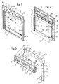
- the furnace front of a built-in oven shown in the figures has above a dashed line indicated furnace door 1 with handle 9 and with door front surface 2 an operating and display surface 3, which is divided in the embodiment in a control surface 4 with or for control elements 5 e.g. with control knobs for the control of oven heating elements, time switches and the like, and with a display surface 6 with or for display elements 7 for the visual display of the values set with the control elements 5.
- a control surface 4 with or for control elements 5 e.g. with control knobs for the control of oven heating elements, time switches and the like
- a display surface 6 with or for display elements 7 for the visual display of the values set with the control elements 5.
- the furnace front element 8 with one-piece operating surface 4 of the control and display surface 3 has on both sides the oven door 1 frame-like bordering front strips 10 which extend over the entire height of the oven door 1 and are integrally connected as a U-shaped punched and bent part with the control surface 4 flush ,
- Each front strip 10 has a right angle bent bevel 11, which extend parallel to the direction of movement 13 of the oven door 1 in the open position and enclose this oven door 1 portal.
- These bends 11 have in the form of slightly beveled extensions fasteners 12, with a the feed opening of a baking oven muffle 15 (indicated by dashed lines in FIG. 2 ) surrounding oven flange 16 at fastening points 14, for example by means of screws.
- the fasteners 12 are extensions of the right angles from the front strips 10 integrally projecting bends 11 with the mentioned attachment points 14.
- Begrenzungsflansche 17 are provided.
- FIG. 3 shows an exploded view of the structure of the furnace front according to the Figures 1 and 2 , Evident is the furnace front element 8 with the control surface 4 and with the down freely projecting front strips 10 including folds 11 and Begrenzungsflanschen 17.
- the control surface 4 has suitable openings for the aforementioned controls 5 and the like.
- a metallic cross member 20 as the display surface 6 forming component, which also has corresponding openings for display elements, such as optical LED components.
- the attachment of the cross member 20 is effected by bonding by means of a double-sided provided with an adhesive layer plate 18 made of plastic material.
- This plate 18 serves as a spacer for the parts to be joined together 4 and 20/6 with a distance a corresponding to the thickness of the plate 18.
- the display surface 6 of the cross member 20 thus protrudes the operating surface 4, so in this joint, for example, a partially transparent lens 19 flush can be attached to the control surface 4.
- this plate 18 has 7 suitable openings for the display members.
- control and display surface 3 in particular their transverse stability is substantially increased in comparison with the individual elements forming them, so that, inter alia, the handling and transport of the furnace front is improved and simplified.
- the cross member 20 has on the rear side of a right-angled protruding leg 21 of its front surface as a support for display elements and the like.
Landscapes
- Engineering & Computer Science (AREA)
- Chemical & Material Sciences (AREA)
- Combustion & Propulsion (AREA)
- Mechanical Engineering (AREA)
- General Engineering & Computer Science (AREA)
- Baking, Grill, Roasting (AREA)
- Electric Ovens (AREA)
Abstract
Description
- Die Erfindung bezieht sich auf einen Backofen oder ein anderes Haushaltsgerät mit einem, eine Bedienfläche sowie zumindest beidseitig die Ofentür einfassende Frontleisten aufweisenden, einstückigen und aus Blechmaterial bestehenden Ofenfrontelement.
- Bei derartigen, vorzugsweise im Tiefziehverfahren hergestellten, im Wesentlichen ebenflächigen und nur niedrige Abkantungen aufweisenden Ofenfrontelementen mit einer großflächigen Bedienfläche und davon abstehenden schmalen Frontleisten, d.h. mit einem im Wesentlichen ebenen und schmalen, insbesondere U-förmig freiragende Elemente aufweisenden, in einem Stanz- und Tiefziehverfahren vorgefertigten Bauteil besteht einerseits das transporttechnische Problem des gehäuften und auf engstem Raum gebündelten bzw. gestapelten Verpackens und Transports von labilen, d.h. leicht verformbaren, dünnwandigen Blechteilen und andererseits das Problem, ein derart instabiles Blechteil als notwendigerweise formstabilen Träger für Funktionselemente wie elektrische Schalter, z.B. Zeitschalter, Tastaturen oder dergleichen, zu verwenden.
- Der vorliegenden Erfindung liegt die Aufgabe zugrunde, einen Backofen der eingangs genannten Art so auszugestalten, dass einerseits trotz weitgehend ebenflächiger und mit freiragenden Elementen versehener Gestaltung der Blechteile und damit verbundener Instabilität des Ofenfrontelements eine für die im Zuge der Fertigung notwendige Verpackung, Transport und Weiterbearbeitung, z.B. Assemblierung, ausreichende Formstabilität des Ofenfrontelements erhalten wird und andererseits von der Frontebene abstehende, bzw. abgekantete Elemente, z.B. Träger für Bauteile, vorgesehen sein können und dies mittels einfacher fertigungstechnischer Maßnahmen.
- Diese Aufgabe wird durch die erfindungsgemäßen Maßnahmen bei einem Backofen der eingangs genannten Art dadurch gelöst, dass zumindest die Bedienfläche mit einem ebenfalls aus Blechmaterial bestehenden und einen Bestandteil der Bedien- und Anzeigefläche bildenden Querträger verbunden ist, der als Träger für die Bedienung und Anzeige von Funktionsorganen des Backofens ausgebildet ist.
- Durch die fertigungstechnisch sehr einfach durchzuführende mechanische Verbindung des Ofenfrontelements mit einem Querträger werden diese als Einzelteile relativ instabilen Teile zu einer formstabilen und planen Einheit sandwichartig vorzugsweise durch Kleben vereinigt. Dabei werden bei der Herstellung dieser Einzelteile bei Anwendung der Tiefziehtechnik tiefe und deshalb problematische Abkantungen vermieden, indem solche weit auskragenden Abkantungen oder Schenkel als problemlos verformbare Biegeteile ausgebildet werden können. So kann insbesondere der genannte Querträger als Träger für der Bedien- und Anzeigefläche des Backofens zugeordnete Organe wie elektrische Schalter, Zeitglieder, Taster oder dergleichen dienen und hierfür auch tief von der ebenen Frontfläche abgebogene Schenkel besitzen.
- Gemäß einer bevorzugten Ausführungsform der Erfindung ist vorgesehen, dass der Querträger die Bedienfläche des Ofenfrontelements überragt und als Bedien- und vorzugsweise als Anzeigefläche für Funktionsorgane des Backofens dient. Dadurch besteht in fertigungstechnisch einfacher Weise die Möglichkeit, den Querträger unabhängig vom damit verbundenen Ofenfrontelement mit einer beliebigen Konfiguration, mit Abbiegungen, Fensteröffnungen und dergleichen zu versehen, ohne die Gestaltung und Formstabilität des Ofenfrontelements zu beeinträchtigen.
- So besteht in vorteilhafter Weise die Möglichkeit einer Ausgestaltung, bei der die Frontfläche des Querträgers die Frontfläche der Bedienfläche des Ofenfrontelements mit einem für die Einführung einer z.B. teiltransparenten und mit der Ofenfront flächenbündigen Sichtscheibe geeigneten Abstand hinterragt. Diese Bauweise wird besonders einfach und kostengünstig, wenn als Abstandhalter zwischen der Bedienfläche des Ofenfrontelements und der Frontfläche des Querträgers eine beidseitig mit einer Klebeschicht versehene Platte vorgesehen ist. Mit einem kostengünstigen, vorzugsweise aus nicht-metallischen Kunststoff bestehenden "Klebeband" wird einerseits eine mechanische Verbindung zwischen den beiden Elementen der Bedien- und Anzeigefläche des Backofens und andererseits die Basis für eine flächenbündige Einfügung einer transparenten Sichtscheibe für die Darbietung der Anzeigeorgane des Backofens geschaffen.
- Die Erfindung wird anhand eines in der Zeichnung dargestellten Ausführungsbeispiels nachstehend erläutert.
- Es zeigt:
- Fig. 1
- Die perspektivische Ansicht der Ofenfront eines Backofens,
- Fig. 2
- die rückseitige Ansicht der Ofenfront mit angedeuteter Ofenmuffel,
- Fig. 3
- die rückseitige Ofenfront in Explosionsdarstellung ihrer Bestandteile.
- Die in den Figuren gezeigte Ofenfront eines Einbau-Backofens besitzt oberhalb einer gestrichelt angedeuteten Ofentür 1 mit Handgriff 9 und mit Türfrontfläche 2 eine Bedien- und Anzeigefläche 3, die beim Ausführungsbeispiel geteilt ist in eine Bedienfläche 4 mit bzw. für Bedienorgane 5 z.B. mit Bedienknebeln für die Steuerung von Backofen-Heizelementen, Zeitschaltern und dergleichen und mit einer Anzeigefläche 6 mit bzw. für Anzeigeorgane 7 für die optische Anzeige der mit den Bedienorganen 5 eingestellten Werte.
- Das Ofenfrontelement 8 mit einstückiger Bedienfläche 4 der Bedien- und Anzeigefläche 3 besitzt beidseitig die Ofentür 1 rahmenartig einfassende Frontleisten 10, die sich über die gesamte Höhe der Ofentür 1 erstrecken und einstückig als U-förmiges Stanz- und Biegeteil mit der Bedienfläche 4 flächenbündig verbunden sind. Jede Frontleiste 10 besitzt eine rechtwinklig abgebogene Abkantung 11, die sich parallel zur Bewegungsrichtung 13 der Ofentür 1 in die Öffnungsstellung erstrecken und diese Ofentür 1 portalmäßig einfassen. Diese Abkantungen 11 besitzen in Form von leicht abgekanteten Verlängerungen Befestigungselemente 12, die mit einem die Beschickungsöffnung einer Backofenmuffel 15 (gestrichelt angedeutet in
Figur 2 ) umgebenden Backofenflansch 16 an Befestigungsstellen 14 z.B. mittels Schrauben verbunden sind. Die Befestigungselemente 12 sind Verlängerungen der rechtwinklig von den Frontleisten 10 einstückig abstehenden Abkantungen 11 mit den erwähnten Befestigungsstellen 14. An den äußeren Begrenzungen der Frontleisten 10 sind einstückig kurze, rechtwinklig abgebogene seitliche Begrenzungsflansche 17 vorgesehen. -
Figur 3 zeigt in Explosionsdarstellung den Aufbau der Ofenfront gemäß denFiguren 1 und 2 . Zu erkennen ist das Ofenfrontelement 8 mit der Bedienfläche 4 und mit den nach unten frei auskragenden Frontleisten 10 samt Abkantungen 11 und Begrenzungsflanschen 17. Die Bedienfläche 4 besitzt geeignete Öffnungen für die erwähnten Bedienorgane 5 und dergleichen. Auf die Bedienfläche 4 aufsetzbar ist ein z.B. metallischer Querträger 20 als die Anzeigefläche 6 bildender Bauteil, der ebenfalls entsprechende Öffnungen für Anzeigeorgane, z.B. optische LED-Bauelemente, aufweist. Die Befestigung des Querträgers 20 erfolgt durch Kleben mittels einer beidseitig mit einer Klebeschicht versehenen Platte 18 aus Kunststoffmaterial. Diese Platte 18 dient als Abstandshalter für die miteinander zu verbindenden Teile 4 und 20/6 mit einem Abstand a entsprechend der Dicke der Platte 18. Die Anzeigefläche 6 des Querträgers 20 hinterragt also die Bedienfläche 4, sodass in dieser Fuge z.B. eine teiltransparente Sichtscheibe 19 flächenbündig zur Bedienfläche 4 befestigt werden kann. Auch diese Platte 18 besitzt für die Anzeigeorgane 7 geeignete Öffnungen. - Durch die sandwichartige Bauweise der Bedien- und Anzeigefläche 3 wird insbesondere deren Querstabilität im Vergleich mit den sie bildenden Einzelelementen wesentlich erhöht, sodass unter anderem die Handhabung und der Transport der Ofenfront verbessert und vereinfacht wird.
- Wie in
Figur 2 und 3 gezeigt, besitzt der Querträger 20 rückseitig einen von dessen Frontfläche rechtwinklig abstehenden Schenkel 21 als Träger für Anzeigeorgane und dergleichen.
Claims (5)
- Backofen mit einem, eine Bedienfläche (4) sowie zumindest beidseitig die Ofentür (1) einfassende Frontleisten (10) aufweisenden, einstückigen und aus Blechmaterial bestehenden Ofenfrontelement (8), dadurch gekennzeichnet, dass die Bedienfläche (4) mit einem ebenfalls aus Blechmaterial bestehenden und einen Bestandteil der Bedien- und Anzeigefläche (3) bildenden Querträger (20) fest verbunden ist, der als Träger für Bedienung und Anzeige von Funktionsorganen des Backofens ausgebildet ist.
- Backofen nach Anspruch 1, dadurch gekennzeichnet, dass der Querträger (20) die Bedienfläche (4) des Ofenfrontelements überragt und als Bedien- und vorzugsweise als Anzeigefläche (4, 6) für Funktionsorgane des Backofens dient.
- Backofen nach Anspruch 2, dadurch gekennzeichnet, dass die Frontfläche des Querträgers (20) die Frontfläche der Bedienfläche (4) des Ofenfrontelements mit einem für die Einführung z.B. einer teiltransparenten und mit der Ofenfront flächenbündigen Sichtscheibe (19) geeigneten Abstand hinterragt.
- Backofen nach Anspruch 3, dadurch gekennzeichnet, dass als Abstandshalter zwischen der Bedienfläche (4) des Ofenfrontelements und der Frontfläche des Querträgers (20) eine beidseitig mit einer Klebeschicht versehene Platte (18) vorgesehen ist.
- Backofen nach einem der vorhergehenden Ansprüche, dadurch gekennzeichnet, dass der Querträger (20) einen von dessen Frontfläche winkelig abstehenden Schenkel (21) als Träger für Organe bzw. Bauelemente des Backofens aufweist.
Priority Applications (1)
| Application Number | Priority Date | Filing Date | Title |
|---|---|---|---|
| PL08105314T PL2045531T3 (pl) | 2007-10-01 | 2008-09-11 | Piekarnik |
Applications Claiming Priority (1)
| Application Number | Priority Date | Filing Date | Title |
|---|---|---|---|
| DE200710047004 DE102007047004A1 (de) | 2007-10-01 | 2007-10-01 | Backofen |
Publications (3)
| Publication Number | Publication Date |
|---|---|
| EP2045531A2 true EP2045531A2 (de) | 2009-04-08 |
| EP2045531A3 EP2045531A3 (de) | 2015-02-25 |
| EP2045531B1 EP2045531B1 (de) | 2017-11-15 |
Family
ID=40193578
Family Applications (1)
| Application Number | Title | Priority Date | Filing Date |
|---|---|---|---|
| EP08105314.2A Active EP2045531B1 (de) | 2007-10-01 | 2008-09-11 | Backofen |
Country Status (4)
| Country | Link |
|---|---|
| EP (1) | EP2045531B1 (de) |
| DE (1) | DE102007047004A1 (de) |
| ES (1) | ES2655735T3 (de) |
| PL (1) | PL2045531T3 (de) |
Family Cites Families (8)
| Publication number | Priority date | Publication date | Assignee | Title |
|---|---|---|---|---|
| GB598903A (en) * | 1944-12-18 | 1948-03-01 | Corner & Co Ltd G | Improvements in or relating to gas cookers |
| US2650586A (en) * | 1944-11-13 | 1953-09-01 | Murray Corp | Cabinet range construction |
| GB610717A (en) * | 1945-08-03 | 1948-10-20 | Orme Evans And Company Ltd | Improvements in or relating to cooking, baking, boiling and like apparatus |
| DE2107240A1 (de) * | 1970-02-19 | 1971-09-02 | Industrie A Zanussi SpA, Porde none (Italien) | Kuchenherd, insbesondere fur den Haushalt |
| ES166467Y (es) | 1971-02-26 | 1971-10-16 | Ulgor, S. C. I. | Estructura principal para aparatos domesticos. |
| GB2163547B (en) * | 1984-08-01 | 1987-12-31 | Ti New World Ltd | Improvements in or relating to cookers |
| GB2197457B (en) * | 1986-11-10 | 1990-12-12 | Ti New World Ltd | Improvements in or relating to cooking appliances |
| GB2346438B (en) * | 1999-02-03 | 2001-01-24 | Stoves Group Plc | Fabrication of cooking appliances |
-
2007
- 2007-10-01 DE DE200710047004 patent/DE102007047004A1/de not_active Withdrawn
-
2008
- 2008-09-11 PL PL08105314T patent/PL2045531T3/pl unknown
- 2008-09-11 EP EP08105314.2A patent/EP2045531B1/de active Active
- 2008-09-11 ES ES08105314.2T patent/ES2655735T3/es active Active
Also Published As
| Publication number | Publication date |
|---|---|
| EP2045531B1 (de) | 2017-11-15 |
| DE102007047004A1 (de) | 2009-04-02 |
| PL2045531T3 (pl) | 2018-05-30 |
| EP2045531A3 (de) | 2015-02-25 |
| ES2655735T3 (es) | 2018-02-21 |
Similar Documents
| Publication | Publication Date | Title |
|---|---|---|
| EP0570669B1 (de) | Kochmulde | |
| DE19747769C2 (de) | Haushaltsgerät mit Frontblende | |
| DE102009028808A1 (de) | Innenrahmen für Dunstabzugshaube und Dunstabzugshaube | |
| DE102014221784A1 (de) | Haushaltsgerät mit einer Eingabevorrichtung und einer Kodiervorrichtung | |
| EP1639935B1 (de) | Kastenförmige Bedienblende | |
| DE19504471A1 (de) | Bedienblende für Hausgeräte | |
| EP1678448B1 (de) | Blende für ein gerätegehäuse und verfahren zu dessen herstellung | |
| EP1160513A2 (de) | Haushaltsgerät mit Schalterfront | |
| WO2018177831A1 (de) | Haushaltsgerät mit einer gerätekomponente aufweisend eine schräge streifenfläche und daran angeordnetem funktionsbauteil | |
| EP2199687A2 (de) | Bedieneinheit für ein Haushaltsgerät und Haushaltsgerät | |
| DE102005027192A1 (de) | Sensorelementvorrichtung für eine Bedieneinrichtung eines Kochfeldes und Anordnung eines Kochfeldes in einer Arbeitsplatte | |
| EP2045531B1 (de) | Backofen | |
| DE102020214794A1 (de) | Kochfeld und Verfahren zur Montage eines solchen Kochfelds | |
| WO2012168326A1 (de) | Bedieneinheit für eine fahrzeugkomponente | |
| EP1929840B1 (de) | Halteanordnung für eine kochfeldplatte eines gargerätes | |
| EP2758718B1 (de) | Gargerät mit einer tür | |
| EP1690042B1 (de) | Haushaltsgerät mit einer bedienleiste | |
| DE102009001162A1 (de) | Befestigungsvorrichtung für Bedienteil eines Haushaltsgerätes, Haushaltsgerät und Verfahren zum Befestigen eines Bedienteils | |
| EP2606284B1 (de) | Dunstabzugshaube | |
| DE10350586B4 (de) | Haushaltsgerät mit einer Bedienleiste | |
| EP3628945A1 (de) | Tür für ein haushaltsgerät mit frontseitiger dekorplatte und kantenschutzelement für eine randkante der dekorplatte, sowie haushaltsgerät | |
| DE102014224551B4 (de) | Haushaltsgerät | |
| DE10157221A1 (de) | Blendeneinheit für ein Gargerät | |
| EP1750060A2 (de) | Backofen | |
| DE102010036258A1 (de) | Frontblende für Rackeinschübe |
Legal Events
| Date | Code | Title | Description |
|---|---|---|---|
| PUAI | Public reference made under article 153(3) epc to a published international application that has entered the european phase |
Free format text: ORIGINAL CODE: 0009012 |
|
| AK | Designated contracting states |
Kind code of ref document: A2 Designated state(s): AT BE BG CH CY CZ DE DK EE ES FI FR GB GR HR HU IE IS IT LI LT LU LV MC MT NL NO PL PT RO SE SI SK TR |
|
| AX | Request for extension of the european patent |
Extension state: AL BA MK RS |
|
| PUAL | Search report despatched |
Free format text: ORIGINAL CODE: 0009013 |
|
| AK | Designated contracting states |
Kind code of ref document: A3 Designated state(s): AT BE BG CH CY CZ DE DK EE ES FI FR GB GR HR HU IE IS IT LI LT LU LV MC MT NL NO PL PT RO SE SI SK TR |
|
| AX | Request for extension of the european patent |
Extension state: AL BA MK RS |
|
| RIC1 | Information provided on ipc code assigned before grant |
Ipc: F24C 15/08 20060101ALI20150119BHEP Ipc: F24C 7/08 20060101AFI20150119BHEP |
|
| RAP1 | Party data changed (applicant data changed or rights of an application transferred) |
Owner name: BSH HAUSGERAETE GMBH |
|
| 17P | Request for examination filed |
Effective date: 20150825 |
|
| RBV | Designated contracting states (corrected) |
Designated state(s): AT BE BG CH CY CZ DE DK EE ES FI FR GB GR HR HU IE IS IT LI LT LU LV MC MT NL NO PL PT RO SE SI SK TR |
|
| AKX | Designation fees paid |
Designated state(s): AT BE BG CH CY CZ DE DK EE ES FI FR GB GR HR HU IE IS IT LI LT LU LV MC MT NL NO PL PT RO SE SI SK TR |
|
| AXX | Extension fees paid |
Extension state: BA Extension state: AL Extension state: RS Extension state: MK |
|
| GRAP | Despatch of communication of intention to grant a patent |
Free format text: ORIGINAL CODE: EPIDOSNIGR1 |
|
| INTG | Intention to grant announced |
Effective date: 20170622 |
|
| GRAS | Grant fee paid |
Free format text: ORIGINAL CODE: EPIDOSNIGR3 |
|
| GRAA | (expected) grant |
Free format text: ORIGINAL CODE: 0009210 |
|
| AK | Designated contracting states |
Kind code of ref document: B1 Designated state(s): AT BE BG CH CY CZ DE DK EE ES FI FR GB GR HR HU IE IS IT LI LT LU LV MC MT NL NO PL PT RO SE SI SK TR |
|
| REG | Reference to a national code |
Ref country code: CH Ref legal event code: EP Ref country code: GB Ref legal event code: FG4D Free format text: NOT ENGLISH Ref country code: AT Ref legal event code: REF Ref document number: 946664 Country of ref document: AT Kind code of ref document: T Effective date: 20171115 |
|
| REG | Reference to a national code |
Ref country code: IE Ref legal event code: FG4D Free format text: LANGUAGE OF EP DOCUMENT: GERMAN |
|
| REG | Reference to a national code |
Ref country code: DE Ref legal event code: R096 Ref document number: 502008015723 Country of ref document: DE |
|
| REG | Reference to a national code |
Ref country code: ES Ref legal event code: FG2A Ref document number: 2655735 Country of ref document: ES Kind code of ref document: T3 Effective date: 20180221 |
|
| REG | Reference to a national code |
Ref country code: NL Ref legal event code: MP Effective date: 20171115 |
|
| REG | Reference to a national code |
Ref country code: LT Ref legal event code: MG4D |
|
| PG25 | Lapsed in a contracting state [announced via postgrant information from national office to epo] |
Ref country code: NO Free format text: LAPSE BECAUSE OF FAILURE TO SUBMIT A TRANSLATION OF THE DESCRIPTION OR TO PAY THE FEE WITHIN THE PRESCRIBED TIME-LIMIT Effective date: 20180215 Ref country code: LT Free format text: LAPSE BECAUSE OF FAILURE TO SUBMIT A TRANSLATION OF THE DESCRIPTION OR TO PAY THE FEE WITHIN THE PRESCRIBED TIME-LIMIT Effective date: 20171115 Ref country code: FI Free format text: LAPSE BECAUSE OF FAILURE TO SUBMIT A TRANSLATION OF THE DESCRIPTION OR TO PAY THE FEE WITHIN THE PRESCRIBED TIME-LIMIT Effective date: 20171115 Ref country code: SE Free format text: LAPSE BECAUSE OF FAILURE TO SUBMIT A TRANSLATION OF THE DESCRIPTION OR TO PAY THE FEE WITHIN THE PRESCRIBED TIME-LIMIT Effective date: 20171115 Ref country code: NL Free format text: LAPSE BECAUSE OF FAILURE TO SUBMIT A TRANSLATION OF THE DESCRIPTION OR TO PAY THE FEE WITHIN THE PRESCRIBED TIME-LIMIT Effective date: 20171115 |
|
| PG25 | Lapsed in a contracting state [announced via postgrant information from national office to epo] |
Ref country code: GR Free format text: LAPSE BECAUSE OF FAILURE TO SUBMIT A TRANSLATION OF THE DESCRIPTION OR TO PAY THE FEE WITHIN THE PRESCRIBED TIME-LIMIT Effective date: 20180216 Ref country code: LV Free format text: LAPSE BECAUSE OF FAILURE TO SUBMIT A TRANSLATION OF THE DESCRIPTION OR TO PAY THE FEE WITHIN THE PRESCRIBED TIME-LIMIT Effective date: 20171115 Ref country code: BG Free format text: LAPSE BECAUSE OF FAILURE TO SUBMIT A TRANSLATION OF THE DESCRIPTION OR TO PAY THE FEE WITHIN THE PRESCRIBED TIME-LIMIT Effective date: 20180215 Ref country code: HR Free format text: LAPSE BECAUSE OF FAILURE TO SUBMIT A TRANSLATION OF THE DESCRIPTION OR TO PAY THE FEE WITHIN THE PRESCRIBED TIME-LIMIT Effective date: 20171115 |
|
| PG25 | Lapsed in a contracting state [announced via postgrant information from national office to epo] |
Ref country code: CZ Free format text: LAPSE BECAUSE OF FAILURE TO SUBMIT A TRANSLATION OF THE DESCRIPTION OR TO PAY THE FEE WITHIN THE PRESCRIBED TIME-LIMIT Effective date: 20171115 Ref country code: DK Free format text: LAPSE BECAUSE OF FAILURE TO SUBMIT A TRANSLATION OF THE DESCRIPTION OR TO PAY THE FEE WITHIN THE PRESCRIBED TIME-LIMIT Effective date: 20171115 Ref country code: EE Free format text: LAPSE BECAUSE OF FAILURE TO SUBMIT A TRANSLATION OF THE DESCRIPTION OR TO PAY THE FEE WITHIN THE PRESCRIBED TIME-LIMIT Effective date: 20171115 Ref country code: CY Free format text: LAPSE BECAUSE OF FAILURE TO SUBMIT A TRANSLATION OF THE DESCRIPTION OR TO PAY THE FEE WITHIN THE PRESCRIBED TIME-LIMIT Effective date: 20171115 Ref country code: SK Free format text: LAPSE BECAUSE OF FAILURE TO SUBMIT A TRANSLATION OF THE DESCRIPTION OR TO PAY THE FEE WITHIN THE PRESCRIBED TIME-LIMIT Effective date: 20171115 |
|
| REG | Reference to a national code |
Ref country code: DE Ref legal event code: R097 Ref document number: 502008015723 Country of ref document: DE |
|
| PG25 | Lapsed in a contracting state [announced via postgrant information from national office to epo] |
Ref country code: RO Free format text: LAPSE BECAUSE OF FAILURE TO SUBMIT A TRANSLATION OF THE DESCRIPTION OR TO PAY THE FEE WITHIN THE PRESCRIBED TIME-LIMIT Effective date: 20171115 |
|
| PLBE | No opposition filed within time limit |
Free format text: ORIGINAL CODE: 0009261 |
|
| REG | Reference to a national code |
Ref country code: FR Ref legal event code: PLFP Year of fee payment: 11 |
|
| STAA | Information on the status of an ep patent application or granted ep patent |
Free format text: STATUS: NO OPPOSITION FILED WITHIN TIME LIMIT |
|
| PG25 | Lapsed in a contracting state [announced via postgrant information from national office to epo] |
Ref country code: MT Free format text: LAPSE BECAUSE OF FAILURE TO SUBMIT A TRANSLATION OF THE DESCRIPTION OR TO PAY THE FEE WITHIN THE PRESCRIBED TIME-LIMIT Effective date: 20171115 |
|
| 26N | No opposition filed |
Effective date: 20180817 |
|
| PG25 | Lapsed in a contracting state [announced via postgrant information from national office to epo] |
Ref country code: SI Free format text: LAPSE BECAUSE OF FAILURE TO SUBMIT A TRANSLATION OF THE DESCRIPTION OR TO PAY THE FEE WITHIN THE PRESCRIBED TIME-LIMIT Effective date: 20171115 |
|
| PG25 | Lapsed in a contracting state [announced via postgrant information from national office to epo] |
Ref country code: MC Free format text: LAPSE BECAUSE OF FAILURE TO SUBMIT A TRANSLATION OF THE DESCRIPTION OR TO PAY THE FEE WITHIN THE PRESCRIBED TIME-LIMIT Effective date: 20171115 |
|
| REG | Reference to a national code |
Ref country code: CH Ref legal event code: PL |
|
| REG | Reference to a national code |
Ref country code: BE Ref legal event code: MM Effective date: 20180930 |
|
| REG | Reference to a national code |
Ref country code: IE Ref legal event code: MM4A |
|
| PG25 | Lapsed in a contracting state [announced via postgrant information from national office to epo] |
Ref country code: LU Free format text: LAPSE BECAUSE OF NON-PAYMENT OF DUE FEES Effective date: 20180911 |
|
| PG25 | Lapsed in a contracting state [announced via postgrant information from national office to epo] |
Ref country code: IE Free format text: LAPSE BECAUSE OF NON-PAYMENT OF DUE FEES Effective date: 20180911 |
|
| PG25 | Lapsed in a contracting state [announced via postgrant information from national office to epo] |
Ref country code: LI Free format text: LAPSE BECAUSE OF NON-PAYMENT OF DUE FEES Effective date: 20180930 Ref country code: BE Free format text: LAPSE BECAUSE OF NON-PAYMENT OF DUE FEES Effective date: 20180930 Ref country code: CH Free format text: LAPSE BECAUSE OF NON-PAYMENT OF DUE FEES Effective date: 20180930 |
|
| REG | Reference to a national code |
Ref country code: AT Ref legal event code: MM01 Ref document number: 946664 Country of ref document: AT Kind code of ref document: T Effective date: 20180911 |
|
| PG25 | Lapsed in a contracting state [announced via postgrant information from national office to epo] |
Ref country code: AT Free format text: LAPSE BECAUSE OF NON-PAYMENT OF DUE FEES Effective date: 20180911 |
|
| PG25 | Lapsed in a contracting state [announced via postgrant information from national office to epo] |
Ref country code: PT Free format text: LAPSE BECAUSE OF FAILURE TO SUBMIT A TRANSLATION OF THE DESCRIPTION OR TO PAY THE FEE WITHIN THE PRESCRIBED TIME-LIMIT Effective date: 20171115 Ref country code: HU Free format text: LAPSE BECAUSE OF FAILURE TO SUBMIT A TRANSLATION OF THE DESCRIPTION OR TO PAY THE FEE WITHIN THE PRESCRIBED TIME-LIMIT; INVALID AB INITIO Effective date: 20080911 |
|
| PG25 | Lapsed in a contracting state [announced via postgrant information from national office to epo] |
Ref country code: IS Free format text: LAPSE BECAUSE OF FAILURE TO SUBMIT A TRANSLATION OF THE DESCRIPTION OR TO PAY THE FEE WITHIN THE PRESCRIBED TIME-LIMIT Effective date: 20180315 |
|
| REG | Reference to a national code |
Ref country code: DE Ref legal event code: R084 Ref document number: 502008015723 Country of ref document: DE |
|
| PGFP | Annual fee paid to national office [announced via postgrant information from national office to epo] |
Ref country code: DE Payment date: 20250930 Year of fee payment: 18 |
|
| PGFP | Annual fee paid to national office [announced via postgrant information from national office to epo] |
Ref country code: PL Payment date: 20250829 Year of fee payment: 18 Ref country code: TR Payment date: 20250908 Year of fee payment: 18 |
|
| PGFP | Annual fee paid to national office [announced via postgrant information from national office to epo] |
Ref country code: GB Payment date: 20250923 Year of fee payment: 18 |
|
| PGFP | Annual fee paid to national office [announced via postgrant information from national office to epo] |
Ref country code: FR Payment date: 20250926 Year of fee payment: 18 |
|
| PGFP | Annual fee paid to national office [announced via postgrant information from national office to epo] |
Ref country code: IT Payment date: 20250930 Year of fee payment: 18 |
|
| PGFP | Annual fee paid to national office [announced via postgrant information from national office to epo] |
Ref country code: ES Payment date: 20251020 Year of fee payment: 18 |