EP2045538A2 - Unité d'intérieur pour climatiseur - Google Patents
Unité d'intérieur pour climatiseur Download PDFInfo
- Publication number
- EP2045538A2 EP2045538A2 EP08017123A EP08017123A EP2045538A2 EP 2045538 A2 EP2045538 A2 EP 2045538A2 EP 08017123 A EP08017123 A EP 08017123A EP 08017123 A EP08017123 A EP 08017123A EP 2045538 A2 EP2045538 A2 EP 2045538A2
- Authority
- EP
- European Patent Office
- Prior art keywords
- indoor unit
- air conditioner
- display
- conditioner according
- front panel
- Prior art date
- Legal status (The legal status is an assumption and is not a legal conclusion. Google has not performed a legal analysis and makes no representation as to the accuracy of the status listed.)
- Granted
Links
Images




Classifications
-
- F—MECHANICAL ENGINEERING; LIGHTING; HEATING; WEAPONS; BLASTING
- F24—HEATING; RANGES; VENTILATING
- F24F—AIR-CONDITIONING; AIR-HUMIDIFICATION; VENTILATION; USE OF AIR CURRENTS FOR SCREENING
- F24F1/00—Room units for air-conditioning, e.g. separate or self-contained units or units receiving primary air from a central station
- F24F1/0007—Indoor units, e.g. fan coil units
-
- F—MECHANICAL ENGINEERING; LIGHTING; HEATING; WEAPONS; BLASTING
- F24—HEATING; RANGES; VENTILATING
- F24F—AIR-CONDITIONING; AIR-HUMIDIFICATION; VENTILATION; USE OF AIR CURRENTS FOR SCREENING
- F24F1/00—Room units for air-conditioning, e.g. separate or self-contained units or units receiving primary air from a central station
- F24F1/0007—Indoor units, e.g. fan coil units
- F24F1/0043—Indoor units, e.g. fan coil units characterised by mounting arrangements
- F24F1/0057—Indoor units, e.g. fan coil units characterised by mounting arrangements mounted in or on a wall
-
- F—MECHANICAL ENGINEERING; LIGHTING; HEATING; WEAPONS; BLASTING
- F24—HEATING; RANGES; VENTILATING
- F24F—AIR-CONDITIONING; AIR-HUMIDIFICATION; VENTILATION; USE OF AIR CURRENTS FOR SCREENING
- F24F11/00—Control or safety arrangements
- F24F11/30—Control or safety arrangements for purposes related to the operation of the system, e.g. for safety or monitoring
-
- F—MECHANICAL ENGINEERING; LIGHTING; HEATING; WEAPONS; BLASTING
- F24—HEATING; RANGES; VENTILATING
- F24F—AIR-CONDITIONING; AIR-HUMIDIFICATION; VENTILATION; USE OF AIR CURRENTS FOR SCREENING
- F24F13/00—Details common to, or for air-conditioning, air-humidification, ventilation or use of air currents for screening
- F24F13/20—Casings or covers
-
- F—MECHANICAL ENGINEERING; LIGHTING; HEATING; WEAPONS; BLASTING
- F24—HEATING; RANGES; VENTILATING
- F24F—AIR-CONDITIONING; AIR-HUMIDIFICATION; VENTILATION; USE OF AIR CURRENTS FOR SCREENING
- F24F11/00—Control or safety arrangements
- F24F11/50—Control or safety arrangements characterised by user interfaces or communication
- F24F11/52—Indication arrangements, e.g. displays
-
- F—MECHANICAL ENGINEERING; LIGHTING; HEATING; WEAPONS; BLASTING
- F24—HEATING; RANGES; VENTILATING
- F24F—AIR-CONDITIONING; AIR-HUMIDIFICATION; VENTILATION; USE OF AIR CURRENTS FOR SCREENING
- F24F11/00—Control or safety arrangements
- F24F11/50—Control or safety arrangements characterised by user interfaces or communication
- F24F11/56—Remote control
-
- F—MECHANICAL ENGINEERING; LIGHTING; HEATING; WEAPONS; BLASTING
- F24—HEATING; RANGES; VENTILATING
- F24F—AIR-CONDITIONING; AIR-HUMIDIFICATION; VENTILATION; USE OF AIR CURRENTS FOR SCREENING
- F24F11/00—Control or safety arrangements
- F24F11/70—Control systems characterised by their outputs; Constructional details thereof
- F24F11/72—Control systems characterised by their outputs; Constructional details thereof for controlling the supply of treated air, e.g. its pressure
- F24F11/79—Control systems characterised by their outputs; Constructional details thereof for controlling the supply of treated air, e.g. its pressure for controlling the direction of the supplied air
-
- F—MECHANICAL ENGINEERING; LIGHTING; HEATING; WEAPONS; BLASTING
- F24—HEATING; RANGES; VENTILATING
- F24F—AIR-CONDITIONING; AIR-HUMIDIFICATION; VENTILATION; USE OF AIR CURRENTS FOR SCREENING
- F24F13/00—Details common to, or for air-conditioning, air-humidification, ventilation or use of air currents for screening
- F24F13/20—Casings or covers
- F24F2013/207—Casings or covers with control knobs; Mounting controlling members or control units therein
-
- F—MECHANICAL ENGINEERING; LIGHTING; HEATING; WEAPONS; BLASTING
- F24—HEATING; RANGES; VENTILATING
- F24F—AIR-CONDITIONING; AIR-HUMIDIFICATION; VENTILATION; USE OF AIR CURRENTS FOR SCREENING
- F24F2120/00—Control inputs relating to users or occupants
- F24F2120/10—Occupancy
- F24F2120/12—Position of occupants
Definitions
- the present invention relates to an indoor unit of an air conditioner capable of improving the design quality of the front side of an indoor unit body.
- a housing serving as the body of the indoor unit includes a front portion constituted by a front frame, a front panel, and a display cover, and a rear portion constituted by a base frame.
- the front panel is attached to the front frame, and serves as a design surface.
- the display cover is attached to a lower portion of the front panel to extend in lateral directions from the center in the width direction thereof, and serves as a display member.
- the baseframe houses a heat exchanger, an air blower, and so forth.
- the display cover is formed of a transparent or translucent synthetic resin allowing the transmission therethrough of light, and is fixed to the front panel by a wedge member. Further, the display cover is provided with a plurality of display portions on the outer surface (the front surface) or the inner surface (the back surface) thereof. The display portions are laterally provided by printing or the like and highlighted by light applied from the back side. Further, a word or phrase explaining the content of the information displayed by each of the display portions, e.g., letters such as OPERATION, TIMER, INTERNAL CLEANING, HUMIDITY, OUTDOOR, FILTER, ODOR, VENTILATION, and DUST, is printed at a position above the vicinity of the display portion on the front surface.
- letters such as OPERATION, TIMER, INTERNAL CLEANING, HUMIDITY, OUTDOOR, FILTER, ODOR, VENTILATION, and DUST
- a light-emitting device such as an LED (light-emitting diode) is provided to be located on the back side of the display cover. As the light emitted from the light-emitting device is transmitted through the display cover, the respective display portions printed on the display cover and the contents of the corresponding display information are selectively illuminated to highlight corresponding information (patent documents No.1, for example).
- Patent Documents No.1 Japanese Unexamined Patent Application Publication No. 2005-147432 ( Figs. 2 to 4 ).
- Such an issue can be overcome by, for example, providing a half-mirror film to a surface of the display to make the shape of the display invisible in the light-off state of the light-emitting device.
- a half-mirror film to make the shape of the display invisible in the light-off state of the light-emitting device.
- the half-mirror imposes another design constraint.
- the dominant color of the indoor unit is white in accordance with the color of the wallpaper of a room.
- the half mirror which is similar to a mirror surface, conversely emphasizes the presence of the indoor unit.
- the front surface includes a curved portion, an object reflected by the half mirror appears in a larger or smaller size than the original size thereof, and thus the presence of the indoor unit is further emphasized.
- the front surface can be formed only by a flat surface.
- the design surface on the front side is constituted by two components, i.e., the front panel and the transparent or translucent display cover attached to the front panel and provided with the display portions.
- This structure is disadvantageous in that the design surface includes a dividing line, which constitutes another significant design constraint.
- An indoor unit of an air conditioner has the following configuration. That is, the indoor unit of an air conditioner includes a front panel and a display portion positioned at a front portion of an indoor unit body.
- the front panel is openable and closable.
- the display portion includes a light-emitting device controllable in the lighting on and off thereof, and is provided inside the indoor unit body to face the front panel, to display operation information such as an indoor state or an operation setting state.
- the front panel is formed of a transparent or translucent material, and is provided with a decorative layer on the inner or outer surface thereof or inside thereof.
- the decorative layer has non-reflectivity, allows the transmission therethrough of light emitted from the light-emitting device, and prevents the interior of the indoor unit body from being seen through from outside of the indoor unit in a light-off state.
- the front panel is formed of the transparent or translucent material. Further, on the inner or outer surface of the front panel or inside the front panel, the non-reflective decorative layer is provided which allows the transmission therethrough of the light emitted from the light-emitting device, but which prevents the interior of the indoor unit body from being seen through from outside of the indoor unit in the light-off state. In the light-off state of the light-emitting device, therefore, any depiction relating to the display portion is not shown on the front surface of the front panel. So, display contents are depicted on the front surface of the front panel only after the light-up of the light-emitting device. Accordingly, a design constraint imposed by the display contents is eliminated, and the degree of design freedom is increased.
- a housing of an indoor unit body 1 includes a front portion constituted only by a front frame 3 and a front panel 2 which is attached to the front frame 3 to be openable and closable with respect thereto and serves as a design surface, and a rear portion constituted by a base frame 6 for housing a heat exchanger 4, an air blower 5, and so forth.
- the front panel 2 is formed of a transparent or translucent material including an ABS (acrylonitrile butadiene styrene) resin having high chemical resistance and insolubility in by a paint and so forth. If the outer surface (the front surface) or the inner surface (the back surface) of the front panel 2 is not provided with anything, an object can be seen through the front panel 2, i.e., the interior of the indoor unit body 1 can always be seen through. As illustrated in Figs. 2 to 4 , however, the front panel 2 is provided with a decorative layer 10, which is homogeneously painted or printed on the entire area (the entire surface) of a back surface of the front panel 2, and which has low reflectivity and a color of high brightness, such as white and beige. Accordingly, the interior of the indoor unit body 1 cannot be seen through from outside of the indoor unit. However, light emitted from inside the indoor unit body 1 can be transmitted through the decorative layer 10, as described later.
- ABS acrylonitrile butadiene styrene
- the decorative layer 10 is formed into a thickness of 20 ⁇ m or more. If the decorative layer 10 is formed into a thickness of less than 20 ⁇ m, the interior of the indoor unit body 1 is seen through. That is, the thickness of 20 ⁇ m or more of the decorative layer 10 is a minimum thickness necessary for preventing the interior of the indoor unit body 1 from being seen through from outside of the indoor unit.
- the upper limit of the thickness of the decorative layer 10 slightly varies depending on the color of the employed paint and so forth. Irrespective of the color to be employed, however, it is needless to say that the upper limit is set to a thickness allowing the light emitted from a light-emitting device 9 described later to be transmitted through the decorative layer 10.
- the decorative layer 10 may alternatively be provided on the front surface of the front panel 2.
- the thickness of the front panel 2 it is necessary to prevent the flowing direction of the resin from being generated as a line in a molding process, and to make the resin easily flow.
- each of the lateral ends of the inner surface of the front panel 2 is equipped with a front panel holder 13, which is provided with a support arm 11 and a locking clamp 12 for attaching the front panel 2 to the front frame 3, to prevent the portions shaped for fixation from being seen from outside of the indoor unit.
- portions of the front panel 2 to install the front panel holders 13 have also been previously provided with the decorative layer 10 such that the presence of the front panel holders 13 at the portions is hidden from outside of the indoor unit.
- the color of the front panel holders 13 may be made the same as the color of the decorative layer 10.
- the front panel 2 is fixed to the front frame 3 via the support arm 11 and the locking clamp 12 provided to each of the front panel holders 13, and can be attached to and detached from the front frame 3 and opened and closed with the support arm 11 functioning as a fulcrum.
- the light-emitting device 9 is mounted on a display board 14.
- a white LED light is employed as the light-emitting device 9.
- the display board 14 is held by a display board fixing member 15.
- the display board fixing member 15 includes display windows 16 each formed into a shape desired to be depicted in the light-on state of the light-emitting device 9. As illustrated in Fig. 4 , in the closed state of the front panel 2, the display board fixing member 15 is constantly biased forward by a coil spring 17 disposed on the back side thereof, and the display windows 16 are made in close contact with and fixed to the decorative layer 10 of the front panel 2.
- each of the display windows 16, i.e., the size of a word or phrase or a pictogram displayed on the surface of the front panel 2 needs to be 4 mmx4 mm or more for visibility.
- the upper limit of the size is preferred to be set to 50 mmx50 mm or less, i.e., a size not excessively large in terms of design. Accordingly, display contents can be easily recognized, and an area provided with a necessary number of the display contents can be easily secured. Further, the shape of each of the display windows 16 determines the shape to be displayed. Therefore, a highly accurate window shape can be easily obtained.
- a switch capable of changing the illuminance of the display portion and turning off the light is provided to the indoor unit body 1 or a remote controller (not illustrated) of the air conditioner. Accordingly, it is possible to turn off the light of the display portion at bedtime in the nighttime, for example, and thus to prevent the light from disturbing the sleep of the user.
- the present example includes four display contents, i.e., a temperature display 19, a human detection display 20, an energy saving level display 21, and a cleaning display 22.
- the temperature display 19 displays the set temperature and the sensible temperature actually felt by a person, which is based on the room temperature, the humidity, and the temperature of the walls and floor, at intervals of 0.5°C in accordance with the situation at a given time.
- the room temperature may be displayed instead of the sensible temperature.
- the intervals of 0.5°C may be replaced by intervals of 1°C. If the sensible temperature is displayed at the intervals of 0.5°C, subtle display of a temperature close to the temperature actually felt by a person can be provided. Accordingly, temperature setting suitable for the user can be easily performed while viewing the display portion of the indoor unit body 1. As a result, the comfort is improved.
- the human detection display 20 displays the position and the range of activity of a person detected by an infrared sensor 50 provided to the indoor unit body 1. Accordingly, the user can visually understand the operational state of the indoor unit. Further, the indoor unit may be provided with a function of detecting the position and the range of activity of a person through the infrared sensor 50 and automatically changing the wind direction on the basis of the information obtained from the detection, and to use the human detection display 20 for displaying the wind direction. In this case, the user can visually understand the operational state of the indoor unit.
- the energy saving level display 21 displays the level of energy saving by the number of leaves. The greater number of the leaves indicates the higher energy saving level. Further, the energy saving level can be set by the remote controller, and is changed depending on whether or not each of the temperature of the walls and floor, the position of a person, and the amount of activity of a person is activated. Accordingly, the energy saving level can be checked while viewing the display portion of the indoor unit body 1.
- the cleaning display 22 is lighted up in an automatic cleaning operation of a filter and a drying operation of the heat exchanger 4.
- the above-described display portion normally displays the current state of inside of the room. However, after the setting is changed, it is configured to display only a changed content of the setting for only a predetermined time. That is, upon a change in the set temperature, the temperature display 19 is lighted up and displays the changed set temperature for a predetermined time. Further, upon a change in the energy saving level, the energy saving level display 21 is lighted up and displays the changed energy saving level for a predetermined time. Accordingly, the changed contents can be checked while viewing the display portion of the indoor unit body 1.
- the color of the light-emitting device 9 is all white to make the color of the decorative layer 10 appear to the front, and to unify the color of the light emitted from the light-emitting device 9.
- the color appearing to the front is the mixture of the two colors.
- the intended color (the color of the decorative layer 10) can be obtained, and the design is simplified.
- the intended color (the color of the decorative layer 10) can also be obtained by using the light-emitting device 9 capable of creating the same light color as the color of the decorative layer 10.
- the white light color and the white decorative layer 10 were employed, a display with a highest-class feeling was obtained.
- the color appearing to the front does not necessarily need to be unified.
- the color may be changed in accordance with the display content to permit visual distinction between the display contents, as in a case in which the energy saving level display 21 is displayed in a green color, for example.
- any depiction relating to the display portion is not shown on the front surface of the front panel 2, and only the decorative layer 10 is visible. Therefore, the presence of the display portion is unnoticed.
- the light-emitting device 9 If the light-emitting device 9 is lighted up, the generated light is transmitted through the display windows 16 and further through the decorative layer 10, as illustrated in Fig. 6 .
- the emitted light appears to have the shapes of the display windows 16, as viewed from the front side.
- the display board fixing member 15 is biased forward by the coil spring 17, and the display windows 16 are in close contact with and fixed to the decorative layer 10 of the front panel 2.
- a clearance allowing the leakage and spread of the light does not exist between the decorative layer 10 and the display windows 16. Therefore, the outline (the display shape) of each of the display windows 16 is distinctly displayed without being obscured.
- the temperature display 19 displays the sensible temperature based on the room temperature and the humidity. If the energy saving level is increased by one level with the use of the remote controller, the temperature display 19 shifts to the display of the sensible temperature further in consideration of the radiant heat from the walls and floor and so forth. Further, if the temperature of the floor is low in a cooling operation, the operation frequency is reduced to perform an energy saving operation, and one of the leaves of the energy saving level display 21 is lighted up.
- the human detection display 20 displays the position and the range of activity of a person. If the energy saving level is increased by one level with the use of the remote controller, wind is sent to the location of the person in consideration of his position, and the air-conditioning is not performed in an area in which a person is absent. Thereby, the energy saving operation is performed, and another one of the leaves of the energy saving level display 21 is lighted up. If the energy saving level is further increased by one level, the amount of activity of a person is taken into consideration. Then, if the amount of activity is small, and if the cooling operation is being performed, the set temperature is slightly raised to perform the energy saving operation, and another one of the leaves of the energy saving level display 21 is lighted up.
- the reduction of the illuminance and the turning off of the light can be performed with the use of the switch provided to the indoor unit body 1 or the remote controller of the air conditioner. Accordingly, the issue of the design constraint does not arise.
- the front panel 2 is formed of the transparent or translucent material, and the back surface of the front panel 2 is provided with the decorative layer 10 by painting or printing.
- the light-emitting device 9 is lighted up from the back side of the front panel 2 through the display windows 16, and decorative layer 10 prevents the interior of the indoor unit body 1 from being seen through, but allows the transmission therethrough of the light emitted from the light-emitting device 9.
- any depiction relating to the display portion is not shown on the front surface of the front panel 2, and the display contents can be depicted on the front surface of the front panel 2 only after the light-up of the light-emitting device 9. Accordingly, the design constraint imposed by the display contents is eliminated, and thus an unconstrained design can be obtained.
- the design surface on the front side is constituted solely by the single front panel 2. Therefore, the dividing line formed by the structure constituted by a plurality of components is not generated, and thus an unconstrained design can be obtained. Further, the number of components is reduced, and thus the costs can be reduced.
- the decorative layer 10 is formed of the paint having low reflectivity. Therefore, diffuse reflection is not caused by the decorative layer 10. Thus, it is possible to suppress the leakage of the light emitted from the light-emitting device 9 to the outside of the display portion. Accordingly, the front panel 2 can be formed into a curved shape, and the design constraint on the shape of the front panel 2 is eliminated. As a result, the degree of design freedom is increased.
- Fig. 7 is an enlarged cross-sectional view illustrating a display portion of an indoor unit of an air conditioner according to a second embodiment of the present invention, as viewed from a lateral side.
- the same components as the components of the above-described first embodiment illustrated in Fig. 4 are assigned with the same reference numerals.
- the display windows 16 are formed into simple shapes such as squares and circles, and a mask-like display sheet 18, from which portions having shapes desired to be depicted have been cut out, and the remaining portion of which can block light, is stuck on the front side of the display windows 16.
- the above relationship may be reversed, i.e., the portions having shapes desired to be depicted may be formed by the display sheet 18 which can block light, and the light may be transmitted through the surroundings of the portions.
- the other parts of the configuration of the present embodiment are similar to those of the first embodiment described above.
- the display portion is formed by the display sheet 18 capable of blocking light, in which the portions having shapes desired to be depicted have been cut out or left. Accordingly, in addition to effects similar to the effects of the first embodiment described above, the present embodiment can simplify the structure of the display windows 16 and easily obtain minute display shapes.
- a desired pattern such as a wood-grain pattern and a marble pattern, can be easily depicted.
- the air conditioner is the electric appliance which consumes the largest amount of electric energy among household appliances. This is attributed to the fact that one air conditioner, which had been installed per household, has been installed per room in recent years. Therefore, the air conditioner is subject to energy regulation under the Energy Saving Law, and technologies for saving energy consumed by the air conditioner are under development.
- FIG. 8 illustrates an example in which the energy consumption W during the operation of the air conditioner is displayed on the front panel 2 as a energy consumption display 23.
- Fig. 9 illustrates an example in which an amount of electric energy consumption from the start of the operation or the amount of energy consumption consumed from the start to the end of the operation is displayed on the front panel 2 as an energy consumption display 24.
- the energy consumption W detected as described above and the operation time h are multiplied to calculate the amount of energy consumption kWh.
- the amount of energy consumption is displayed upon pressing of an energy consumption display button 26 on a remote controller 25 by the user.
- the display of the amount of energy consumption is not limited thereto.
- the amount of energy consumption consumed from the start to the end of the latest operation may be displayed for a predetermined time after the stop of the air conditioner.
- the amount of energy consumption may be constantly displayed during the operation. Further, it may be configured such that the amount of energy consumption consumed in the latest operation is displayed upon pressing of the energy consumption display button 26 by the user after the stop of the air conditioner.
- the amount of energy consumption in each operation is stored to selectively display, for example, the amount of energy consumption used in the past month, the amount of energy consumption from an arbitrary date to the present date, and the amount of energy consumption in a predetermined time period in the past.
- the user can check the amount of energy consumption from the start of the operation or the amount of energy consumption from the start to the end of the operation. Therefore, similarly to the display of the energy consumption as the energy consumption display 23 ( Fig. 8 ), it is possible to obtain the effects of raising awareness of the user to energy saving and promoting actions of the user for energy saving, such as moderate setting of the set temperature of the air conditioner and frequent turning off of the air conditioner in the absence of a person in the room.
- Fig. 10 illustrates an example in which the display of the amount of energy consumption as described above is displayed in another form.
- the electricity cost accumulated from the start of the operation or the electricity cost accumulated from the start to the stop (or the end) of the operation is displayed on the front panel 2 as an electricity cost display 27.
- the amount of energy consumption calculated as described above is converted into the electricity cost by the rate of 22 yen per kWh, for example, to calculate and display the electricity cost for the operation.
- the display of the used electricity cost is the display of the numerical value related to daily life for the user.
- the display content it becomes easier for the user to understand or interpret the display content.
- the electricity cost is displayed upon pressing of an electricity cost display button 28 on the remote controller 25 by the user.
- the display of the electricity cost is not limited thereto.
- the electricity cost used in the latest operation may be displayed for a predetermined time after the stop of the air conditioner.
- the electricity cost may be constantly displayed during the operation. Further, it may be configured such that the electricity cost used in the latest operation is displayed upon pressing of the electricity cost display button 28 by the user after the stop of the air conditioner.
- the amount of energy consumption in each operation is stored so as to selectively display the electricity cost per month, the electricity cost from an arbitrary date to the present date, and the electricity cost in a predetermined time period in the past.
- the display of the electricity cost per month clarifies the ratio of the electricity cost of the air conditioner in the electricity cost paid each month by a household. Accordingly, it is possible to substantially raise awareness of the user to energy saving of the air conditioner.
- Fig. 11 illustrates an example in which the display of the amount of energy consumption as described above is displayed in still another form.
- the amount of energy consumption used from the start of the operation is converted into the amount of CO 2 (carbon dioxide) emissions, and the converted value is displayed on the front panel 2 as a CO 2 emission amount display 29.
- the CO 2 emission amount display 29 displays the amount of CO 2 generated to produce the electricity used (consumed) in the operation of the air conditioner.
- the used amount of energy consumption is converted into the rate of 0.4 kg per kWh, for example, to calculate and display the amount of CO 2 emissions.
- the amount of CO 2 emissions is displayed upon pressing of a CO 2 emission amount display button 30 on the remote controller 25 by the user. Also in this case, however, the display of the amount of CO 2 emissions is not limited thereto.
- the amount of CO 2 emissions in the latest operation may be displayed for a predetermined time after the stop of the air conditioner. Alternatively, the amount of CO 2 emissions may be continuously displayed during the operation. Further, it may be configured such that the amount of CO 2 emissions in the latest operation is displayed upon pressing of the CO 2 emission amount display button 30 by the user after the stop of the air conditioner.
- the amount of energy consumption in each operation is stored to selectively display the amount of CO 2 emissions per month, the amount of CO 2 emissions from an arbitrary date to the present date, and the amount of CO 2 emissions in a predetermined time period in the past.
- the front panel 2 largely displays the energy consumption during the operation of the air conditioner, the amount of energy consumption used in the operation, the electricity cost, or the amount of CO 2 emissions, the awareness of the user to energy saving and prevention of global warming is raised, and the user is motivated to actually perform the energy saving operation.
- the operational states of the air conditioner such as the current room temperature state, the air-conditioned area, the location of a person, and the energy saving operation state, are displayed.
- the user is enabled to check whether or not the power saving operation is on in the current operational state. If the power saving operation is off, the user aware of the off state is motivated to take action to turn on the power saving operation.
- the present example is configured to display the amount of energy consumption used in the operation, the electricity cost, or the amount of CO 2 emissions for a predetermined time after the stop of the operation.
- the user can grasp the result of his efforts for the energy saving operation as the specific numerical value. Accordingly, it is possible to raise consciousness of the user toward the energy saving operation, and to provide the user with a sense of achievement and satisfaction from his energy saving actions.
- the variety of information can be largely displayed on the front panel 2 of the indoor unit body 1. Therefore, the visibility of the information for the user is improved, and a greater amount of information can be provided to the user. Accordingly, it is possible to raise consciousness of the user toward the energy saving operation, as described above. Further, the display of the information enables the user to check the result of the energy saving operation. Therefore, the user can obtain the sense of achievement and satisfaction from his energy saving actions. As a result, energy saving can be further promoted.
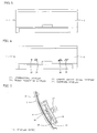
- Fig. 1 is an exploded perspective view of an indoor unit of an air conditioner according to a first embodiment of the present invention, with a front panel detached from the indoor unit;
- 1 indoor unit body
- 2 front panel
- 3 front frame
- 6 base frame
- 9 emitting device
- 10 decorative layer
- 11 support arm
- 12 locking clamp
- 13 front panel holder
- 14 display board
- 15 display board fixing member
- 16 display window
- 17 coil spring (biasing device)
- 18 display sheet
- 19 temperature display
- 20 human detection display
- 21 energy saving level display
- 22 cleaning display
- 23 energy consumption display
- 24 energy consumption display
- 27 electricity cost display
- 29 CO 2 emission amount display
- 50 infrared sensor
Landscapes
- Engineering & Computer Science (AREA)
- Chemical & Material Sciences (AREA)
- Combustion & Propulsion (AREA)
- Mechanical Engineering (AREA)
- General Engineering & Computer Science (AREA)
- Air Conditioning Control Device (AREA)
- Air Filters, Heat-Exchange Apparatuses, And Housings Of Air-Conditioning Units (AREA)
Applications Claiming Priority (2)
| Application Number | Priority Date | Filing Date | Title |
|---|---|---|---|
| JP2007260027 | 2007-10-03 | ||
| JP2008186288A JP5127614B2 (ja) | 2007-10-03 | 2008-07-17 | 空気調和機の室内機 |
Publications (3)
| Publication Number | Publication Date |
|---|---|
| EP2045538A2 true EP2045538A2 (fr) | 2009-04-08 |
| EP2045538A3 EP2045538A3 (fr) | 2010-06-09 |
| EP2045538B1 EP2045538B1 (fr) | 2016-12-28 |
Family
ID=40040123
Family Applications (1)
| Application Number | Title | Priority Date | Filing Date |
|---|---|---|---|
| EP08017123.4A Not-in-force EP2045538B1 (fr) | 2007-10-03 | 2008-09-29 | Unité d'intérieur pour climatiseur |
Country Status (1)
| Country | Link |
|---|---|
| EP (1) | EP2045538B1 (fr) |
Cited By (9)
| Publication number | Priority date | Publication date | Assignee | Title |
|---|---|---|---|---|
| EP2204623A1 (fr) * | 2008-12-31 | 2010-07-07 | LG Electronics Inc. | Unité d'intérieur pour climatiseur |
| CN102072547A (zh) * | 2009-11-19 | 2011-05-25 | 海尔集团公司 | 空调显示盒及其制作工艺 |
| US8804387B2 (en) | 2010-11-02 | 2014-08-12 | Mitsubishi Electric Corporation | Power supply apparatus and controller |
| JP2015055402A (ja) * | 2013-09-11 | 2015-03-23 | 三菱電機株式会社 | 空気調和機 |
| CN107388534A (zh) * | 2017-08-30 | 2017-11-24 | 广东美的制冷设备有限公司 | 显示盒组件及空调器 |
| EP2410253A3 (fr) * | 2010-07-21 | 2018-02-14 | Kabushiki Kaisha Toshiba | Système de gestion de la consommation d'énergie et appareil de gestion de la consommation d'énergie |
| CN109579135A (zh) * | 2018-12-29 | 2019-04-05 | 广东美的暖通设备有限公司 | 空调室内机 |
| EP3489590A4 (fr) * | 2016-07-22 | 2019-08-07 | Mitsubishi Electric Corporation | Unité intérieure de climatiseur |
| US11927353B2 (en) | 2016-07-27 | 2024-03-12 | Johnson Controls Tyco IP Holdings LLP | Building equipment with interactive outdoor display |
Families Citing this family (1)
| Publication number | Priority date | Publication date | Assignee | Title |
|---|---|---|---|---|
| CN113819615B (zh) * | 2021-09-13 | 2023-07-18 | 青岛海尔空调器有限总公司 | 用于控制空调器的方法及装置、空调器 |
Citations (1)
| Publication number | Priority date | Publication date | Assignee | Title |
|---|---|---|---|---|
| JP2005147432A (ja) | 2003-11-12 | 2005-06-09 | Sharp Corp | 表示装置とその表示装置を備えた空気調和機 |
Family Cites Families (4)
| Publication number | Priority date | Publication date | Assignee | Title |
|---|---|---|---|---|
| JP4045147B2 (ja) * | 2002-08-26 | 2008-02-13 | 日立アプライアンス株式会社 | 空気調和機 |
| JP4397803B2 (ja) * | 2004-12-06 | 2010-01-13 | 東芝キヤリア株式会社 | 空気調和機 |
| KR101126958B1 (ko) * | 2005-02-23 | 2012-03-26 | 엘지전자 주식회사 | 공기 조화기 |
| KR20070083046A (ko) * | 2006-02-20 | 2007-08-23 | 엘지전자 주식회사 | 공기조화기의 제어 방법 |
-
2008
- 2008-09-29 EP EP08017123.4A patent/EP2045538B1/fr not_active Not-in-force
Patent Citations (1)
| Publication number | Priority date | Publication date | Assignee | Title |
|---|---|---|---|---|
| JP2005147432A (ja) | 2003-11-12 | 2005-06-09 | Sharp Corp | 表示装置とその表示装置を備えた空気調和機 |
Cited By (12)
| Publication number | Priority date | Publication date | Assignee | Title |
|---|---|---|---|---|
| EP2204623A1 (fr) * | 2008-12-31 | 2010-07-07 | LG Electronics Inc. | Unité d'intérieur pour climatiseur |
| CN102072547A (zh) * | 2009-11-19 | 2011-05-25 | 海尔集团公司 | 空调显示盒及其制作工艺 |
| CN102072547B (zh) * | 2009-11-19 | 2013-06-19 | 海尔集团公司 | 空调显示盒及其制作工艺 |
| EP2410253A3 (fr) * | 2010-07-21 | 2018-02-14 | Kabushiki Kaisha Toshiba | Système de gestion de la consommation d'énergie et appareil de gestion de la consommation d'énergie |
| US8804387B2 (en) | 2010-11-02 | 2014-08-12 | Mitsubishi Electric Corporation | Power supply apparatus and controller |
| JP2015055402A (ja) * | 2013-09-11 | 2015-03-23 | 三菱電機株式会社 | 空気調和機 |
| EP3489590A4 (fr) * | 2016-07-22 | 2019-08-07 | Mitsubishi Electric Corporation | Unité intérieure de climatiseur |
| US10684036B2 (en) | 2016-07-22 | 2020-06-16 | Mitsubishi Electric Corporation | Indoor unit for air-conditioning apparatus |
| US11927353B2 (en) | 2016-07-27 | 2024-03-12 | Johnson Controls Tyco IP Holdings LLP | Building equipment with interactive outdoor display |
| CN107388534A (zh) * | 2017-08-30 | 2017-11-24 | 广东美的制冷设备有限公司 | 显示盒组件及空调器 |
| CN109579135A (zh) * | 2018-12-29 | 2019-04-05 | 广东美的暖通设备有限公司 | 空调室内机 |
| CN109579135B (zh) * | 2018-12-29 | 2024-02-20 | 广东美的暖通设备有限公司 | 空调室内机 |
Also Published As
| Publication number | Publication date |
|---|---|
| EP2045538B1 (fr) | 2016-12-28 |
| EP2045538A3 (fr) | 2010-06-09 |
Similar Documents
| Publication | Publication Date | Title |
|---|---|---|
| EP2045538B1 (fr) | Unité d'intérieur pour climatiseur | |
| ES2612778T3 (es) | Unidad interior de equipo de aire acondicionado | |
| US7913925B2 (en) | Color changing thermostatic controller | |
| CA2619812A1 (fr) | Systeme d'affichage de thermostat a systeme d'avertissement par retroeclairage | |
| JP2003322355A (ja) | 空気調和機の室内ユニット | |
| CN101881503A (zh) | 壁挂式空调室内机 | |
| JP4045147B2 (ja) | 空気調和機 | |
| KR20090125543A (ko) | 공기조화기 및 그 제어 방법 | |
| JP3574753B2 (ja) | 空気清浄機 | |
| USD507757S1 (en) | Control device | |
| JP5660937B2 (ja) | 空気調和機の室内機 | |
| WO2013151487A1 (fr) | Dispositif de notification destiné à des toilettes | |
| KR101533315B1 (ko) | 공기조화기 | |
| CN209037348U (zh) | 一种智能表面控制的汽车内饰出风口 | |
| KR101708680B1 (ko) | 공기 조화기 | |
| JPH09264594A (ja) | 空気調和機のワイヤレスリモコン装置 | |
| JP2003278242A (ja) | 局部洗浄装置 | |
| CN207962289U (zh) | 一种带电容开关的阅读灯 | |
| JPH10267369A (ja) | 空気調和機の表示装置 | |
| KR20050097602A (ko) | 에어컨 전면부 전체에 감성 정보를 표시하는 에어컨 표시장치 | |
| JP2009039144A (ja) | 照明器具付き換気装置 | |
| CN222123316U (zh) | 壁挂式空调室内机及空调器 | |
| JP7751217B2 (ja) | 車両用内装品及び車両用ドア | |
| JP2012083018A (ja) | 空気調和機の室内機 | |
| CN201724358U (zh) | 壁挂式空调室内机 |
Legal Events
| Date | Code | Title | Description |
|---|---|---|---|
| PUAI | Public reference made under article 153(3) epc to a published international application that has entered the european phase |
Free format text: ORIGINAL CODE: 0009012 |
|
| AK | Designated contracting states |
Kind code of ref document: A2 Designated state(s): AT BE BG CH CY CZ DE DK EE ES FI FR GB GR HR HU IE IS IT LI LT LU LV MC MT NL NO PL PT RO SE SI SK TR |
|
| AX | Request for extension of the european patent |
Extension state: AL BA MK RS |
|
| PUAL | Search report despatched |
Free format text: ORIGINAL CODE: 0009013 |
|
| AK | Designated contracting states |
Kind code of ref document: A3 Designated state(s): AT BE BG CH CY CZ DE DK EE ES FI FR GB GR HR HU IE IS IT LI LT LU LV MC MT NL NO PL PT RO SE SI SK TR |
|
| AX | Request for extension of the european patent |
Extension state: AL BA MK RS |
|
| RIC1 | Information provided on ipc code assigned before grant |
Ipc: F24F 11/00 20060101ALI20100506BHEP Ipc: F24F 1/00 20060101AFI20081204BHEP Ipc: F24F 13/20 20060101ALI20100506BHEP |
|
| 17P | Request for examination filed |
Effective date: 20101208 |
|
| AKX | Designation fees paid |
Designated state(s): ES IT |
|
| REG | Reference to a national code |
Ref country code: DE Ref legal event code: 8566 |
|
| GRAP | Despatch of communication of intention to grant a patent |
Free format text: ORIGINAL CODE: EPIDOSNIGR1 |
|
| INTG | Intention to grant announced |
Effective date: 20160728 |
|
| GRAS | Grant fee paid |
Free format text: ORIGINAL CODE: EPIDOSNIGR3 |
|
| GRAA | (expected) grant |
Free format text: ORIGINAL CODE: 0009210 |
|
| AK | Designated contracting states |
Kind code of ref document: B1 Designated state(s): ES IT |
|
| REG | Reference to a national code |
Ref country code: ES Ref legal event code: FG2A Ref document number: 2612778 Country of ref document: ES Kind code of ref document: T3 Effective date: 20170518 |
|
| PLBE | No opposition filed within time limit |
Free format text: ORIGINAL CODE: 0009261 |
|
| STAA | Information on the status of an ep patent application or granted ep patent |
Free format text: STATUS: NO OPPOSITION FILED WITHIN TIME LIMIT |
|
| 26N | No opposition filed |
Effective date: 20170929 |
|
| REG | Reference to a national code |
Ref country code: ES Ref legal event code: GC2A Effective date: 20190416 |
|
| P01 | Opt-out of the competence of the unified patent court (upc) registered |
Effective date: 20230512 |
|
| PGFP | Annual fee paid to national office [announced via postgrant information from national office to epo] |
Ref country code: IT Payment date: 20230810 Year of fee payment: 16 |
|
| PGFP | Annual fee paid to national office [announced via postgrant information from national office to epo] |
Ref country code: ES Payment date: 20231003 Year of fee payment: 16 |
|
| PG25 | Lapsed in a contracting state [announced via postgrant information from national office to epo] |
Ref country code: IT Free format text: LAPSE BECAUSE OF NON-PAYMENT OF DUE FEES Effective date: 20240929 |
|
| REG | Reference to a national code |
Ref country code: ES Ref legal event code: FD2A Effective date: 20251104 |
|
| PG25 | Lapsed in a contracting state [announced via postgrant information from national office to epo] |
Ref country code: ES Free format text: LAPSE BECAUSE OF NON-PAYMENT OF DUE FEES Effective date: 20240930 |