EP2045541A1 - Dispositif de contrôle pour climatiseur - Google Patents
Dispositif de contrôle pour climatiseur Download PDFInfo
- Publication number
- EP2045541A1 EP2045541A1 EP08251886A EP08251886A EP2045541A1 EP 2045541 A1 EP2045541 A1 EP 2045541A1 EP 08251886 A EP08251886 A EP 08251886A EP 08251886 A EP08251886 A EP 08251886A EP 2045541 A1 EP2045541 A1 EP 2045541A1
- Authority
- EP
- European Patent Office
- Prior art keywords
- setting
- image
- display unit
- mode
- item
- Prior art date
- Legal status (The legal status is an assumption and is not a legal conclusion. Google has not performed a legal analysis and makes no representation as to the accuracy of the status listed.)
- Granted
Links
- 238000000034 method Methods 0.000 abstract description 13
- 238000001816 cooling Methods 0.000 description 23
- 238000007791 dehumidification Methods 0.000 description 15
- 238000009423 ventilation Methods 0.000 description 15
- 238000004378 air conditioning Methods 0.000 description 9
- 238000010586 diagram Methods 0.000 description 6
- 238000010276 construction Methods 0.000 description 4
- 238000010438 heat treatment Methods 0.000 description 4
- 238000004891 communication Methods 0.000 description 3
- 239000004988 Nematic liquid crystal Substances 0.000 description 2
- 239000004973 liquid crystal related substance Substances 0.000 description 2
- 230000000295 complement effect Effects 0.000 description 1
- 210000002858 crystal cell Anatomy 0.000 description 1
- 239000000463 material Substances 0.000 description 1
- 238000012986 modification Methods 0.000 description 1
- 230000004048 modification Effects 0.000 description 1
- 230000000704 physical effect Effects 0.000 description 1
Images




Classifications
-
- F—MECHANICAL ENGINEERING; LIGHTING; HEATING; WEAPONS; BLASTING
- F24—HEATING; RANGES; VENTILATING
- F24F—AIR-CONDITIONING; AIR-HUMIDIFICATION; VENTILATION; USE OF AIR CURRENTS FOR SCREENING
- F24F11/00—Control or safety arrangements
- F24F11/30—Control or safety arrangements for purposes related to the operation of the system, e.g. for safety or monitoring
-
- F—MECHANICAL ENGINEERING; LIGHTING; HEATING; WEAPONS; BLASTING
- F24—HEATING; RANGES; VENTILATING
- F24F—AIR-CONDITIONING; AIR-HUMIDIFICATION; VENTILATION; USE OF AIR CURRENTS FOR SCREENING
- F24F11/00—Control or safety arrangements
- F24F11/50—Control or safety arrangements characterised by user interfaces or communication
- F24F11/52—Indication arrangements, e.g. displays
Definitions
- the present invention relates to a control device for an air conditioner, and more specifically, to a control device for an air conditioner, which can increase user convenience by providing various methods of representation of operating conditions.
- the user can easily check the progress of the manipulation of the operating conditions.
- the indoor unit 130 and the outdoor unit 120 are communicatively connected to each other via a network 161. While the air conditioner 140 includes one outdoor unit 120 and one indoor unit 130, the present invention is not limited thereto.
- the air conditioner 140 may include one outdoor unit and a plurality of indoor units, or include a plurality of outdoor units and a plurality of indoor units.
- the database 190 stores various displayable image data in the first display unit 180 and the second display unit 170, and the control unit 160 represents images on the first display unit 180 and the second display unit 170 based on the image data stored in the database 190.
- the control device 110 can display the operating conditions of the air conditioner 140 through the first display unit 180 and the second display unit 170.
- the first display unit 180 can be disposed longitudinally in the control device 110, spaced apart a predetermined gap from the second display unit 170.
- the user can vary the image data in various ways by manipulation.
- the user can select the setting items and use the plurality of function keys for manipulating set values of the selected setting items to represent the setting items and the set values in a first image.
- the image of " set lock” can be converted into the image of " operation mode” and represented on the first display unit 180. Accordingly, the characters indicating " set lock” and the characters indicating " operation mode” , which are different images, can be displayed on the same coordinate plane of the first display unit 180.
- the operating conditions include predetermined setting items, and a first image of the setting items can be represented on the first display unit 180.
- a setting item display part 181 for representing the names of the setting items in the first image and a set value display part 182 for representing set values of the respective setting items in the first image are provided on the first display unit 180.
- the setting items include an operation mode item, a ventilation item, a set temperature item, a room temperature item, a fan speed item, an air flow direction item, a sub function item, and a reservation item.
- the respective setting items have set values that the user can select or change.
- the first image corresponds to the respective setting items and the respective set values of the setting items, and the first image corresponding to the respective setting items and the respective set values are displayed on the setting item display part 181 and set value display part 182, respectively, of the first display unit 180.
- the second display unit 170 On the second display unit 170, only a preset second image can be represented on at least a second region.
- the second display unit 170 has an LCD panel structure like the above-described first display unit 180, and the structure of the LCD panel may be an FTSN.
- the second display unit 170 displays the operating conditions of the air conditioner in a graphic image display method or in an 88-segment method.
- the second image is a preset graphic image.
- the size of the first display unit 180 may be smaller than the size of the second display unit 170. Since a graphic image can be easily visually checked by the user, the size of the second display unit 170 is formed larger in order to easily visually check the operating conditions and precisely ascertain the operating conditions through the display contents of the first display unit 180.
- the operating conditions include predetermined setting items, and a second image of the setting items can be represented on the second display unit 170.
- the second image corresponds to the setting items and respective set values of the setting items. That is, whenever the operating conditions are changed, the second image corresponds to the changed operating conditions.
- the setting items include an operation mode item 171, a ventilation item 172, a set temperature item 173, a room temperature item 174, a fan speed item 175, an air flow direction item 176, a sub function item 177, and a reservation item 178.
- the respective setting items have set values that the user can select or change, and the set values are displayed in a second image on the second display unit 170.
- the second image can be represented in a graphic image as described above.
- the graphic image may be an pictogram which is represented so as to understand by intuition or an icon displayed in a small figure or symbol on the display screen, but the graphic image is not limited to the pictogram or icon.
- the graphic image is an image based on the image data stored in the database 190.
- the graphic image can be represented on the second display unit 170 by lighting the graphic image with the use of the image data stored in the database 190.
- only a set image can be represented by lighting the graphic image on the coordinate plane of the second display unit 170.
- the control unit 160 can apply a signal for transmitting the image data stored in the database 190 on the second display unit 170.
- the signal is a signal which transmits set image data to the second display unit 170 in response to a signal for setting operating conditions and represents an image on the second display unit 170, and also a signal which turns on or off a graphic image on a predetermined coordinate plane of the second display unit 170 based on the set image data.
- a set image can be displayed on the same coordinate plane of the second display unit 170. That is, graphic images specific to the respective setting items and set values are preset on a predetermined coordinate plane of the second display unit 170. For instance, the respective operation items and set values as shown in FIG. 4 are represented in graphic images on the second display unit 170. Referring to FIG. 4 , an image 171 of " operation" indicating an operation mode and a cooling operation graphic image 171a displaying a cooling operation, which is one of the set values of the operation mode, are represented on the second display unit 170.
- the user can select the setting items and use the plurality of function keys for manipulating set values of the selected setting items to represent the setting items and the set values in a second image.
- set values of cooling operation, dehumidification operation, and heating operation in the operation mode item 171 among the setting items can be represented in graphic images 171a, 171b, and 171c on the second display unit.
- the graphic images 171a, 171b, and 171c which are the second image corresponding to the respective set values of cooling operation, dehumidification operation, and heating operation, can be displayed only on a predetermined coordinate plane of the second display unit.
- the first display unit and the second display unit 170 display only the items settable in the air conditioner 140 connected to the control device 110, among the setting items. That is, when the control device 110 requests for settable items to the air conditioner 140, the air conditioner 140 sends settable items to the control device 110. If a signal sent by the air conditioner 140 is a model name, the control unit 160 displays only the setting items corresponding to the model name among all the setting items based on the data stored in the database 190.
- the function keys that can be manipulated by the user include a first function key 151 for inputting a manipulation signal to enter the setting mode, second function keys 152 representing left/right directions, third function keys 153 representing up/down directions, a fourth function key 154 representing set/clear, a fifth function key 155 representing exit, and sub function keys.
- the sub function keys correspond to the items with a high frequency of use among first setting items.
- an operation mode function key 156 is a key for manipulating a set value of the operation mode item
- temperature function keys 157 are keys for manipulating a set value of the set temperature item.
- FIG. 4 is a plan view showing a state in which an " operation mode" item is selected in the display unit of FIG. 3 .
- FIG. 5 is a plan view showing a state in which a " ventilation” item is selected in the display unit of FIG. 3 .
- FIG. 6 is a plan view showing a state in which the set value is changed in the " operation mode" item of the display unit of FIG. 4 .
- the control device 110 When the user presses the first function key 151 for more than a predetermined time period, a manipulation signal for entering a predetermined setting mode is inputted, and the control device 110 enters the setting mode.
- the setting mode is a user setting mode.
- the predetermined time period may be selected in various ways, for example, it may be a value less than 1 second.
- the name of an operable setting item is represented in a first image in the setting item display part 181.
- FIG. 3 a case where the " set lock" item is set as a setting item displayed at an initial stage on the setting item display part 181 is illustrated. That is, if the user presses the first function key 151 for more than a predetermined time period, a predetermined setting mode is entered, and with the setting mode entered, the " set lock” , which is the initial setting item, is displayed in a first image on the setting item display part 181, and " ON" , which is an initial set value, is displayed in a first image on the setting value display unit 182. It is needles to say that the initial setting item and the initial set value may be set in various ways according to user convenience.
- FIG. 4 illustrates a state where the operation mode item 171 is selected. Afterwards, whenever the user presses the first function key 151, the setting item to be selected is sequentially changed.
- FIG. 5 illustrates a state where the ventilation item 172 is selected if the user presses the first function key 151 once more on the first display unit 180 of FIG. 4 .
- the graphic image 171 corresponding to the operation mode item on the second display unit 170 can be changed into a graphic image 172 corresponding to the ventilation item. Accordingly, the first image and second image corresponding to the same setting item can be represented simultaneously on the first display unit 180 and the second display unit 170.
- FIG. 4 illustrates a state where an image representing cooling is selected as a set value in the operation mode item
- FIG. 6 illustrates a state where the set value is changed to " dehumidification" by using the second function keys.
- the image representing dehumidification is displayed on the set value display part 182.
- the set value of the selected setting item is set to the selected set value. If the user presses the fifth function key 155, or does not manipulate the function keys for a predetermined time period, the setting mode is finished.
- a method of setting the setting items excluding the operation mode item is similar to the method of setting in the operation mode item, so a description thereof will be omitted below.
- control device110 is able to perform the setting of setting items in a predetermined setting mode on the first display unit 180 by using the plurality of function keys 150. Subsequently, the user can easily visually check a change in the operating conditions, such as setting items and set values of the respective setting items. Also, because the user operates set values of setting items by the function keys 150 while precisely ascertaining the setting items on the first display unit 180, the operational convenience of the user is greatly enhanced.
- FIG. 7 is a plan view showing another embodiment of a state where an " operation mode" item is selected in the display unit of FIG. 3 .
- FIG. 8 is a plan view showing another embodiment of a state in which a " ventilation” item is selected in the display unit of FIG. 3 .
- FIG. 9 is a plan view showing a case where the set value is " cooling" in the " operation mode” item of the display unit of FIG. 7 .
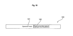
- FIG. 10 is a plan view showing a state in which the set value is changed to " ventilation" in the " operation mode” item of the display unit of FIG. 4 .
- the size of a first image can be varied in response to a manipulation signal inputted from the plurality of function keys.
- a manipulation signal inputted from the plurality of function keys.
- the characters saying " operation mode” become larger than the characters saying " cooling” , which is an image displayed on the set value display part 182.
- the size of the characters saying " operation mode" displayed on the setting item display part 181 is variable.
- the characters saying " cooling” which is an image displayed on the set value display part 182
- the characters saying " operation mode” displayed on the setting item display part 181. That is, the size of the characters saying " cooling" displayed on the set value display part 182 is variable.
- the setting mode enters any one setting mode between the display all mode and the simple display mode. If the user presses the first function key 151 for more than a second predetermined time period, the setting mode enters another setting mode. Specifically, if the user presses the first function key 151 for less than a first predetermined time, the setting mode is set to enter the display all mode, or if the user presses the first function key for more than a second predetermined time period, the setting mode is set to enter the simple display mode.
- the name of an operable setting item is represented in a first image in the setting item display part 181.
- FIG. 7 a case where the " operation mode" item is set as a setting item displayed at an initial stage on the setting item display part 181 is illustrated. That is, with the display all mode entered, the " operation mode” , which is the initial setting item, is displayed in a first image on the setting item display part 181, and " cooling” , which is an initial set value, is displayed in a first image on the setting value display unit 182. It is needles to say that the initial setting item and the initial set value may be set in various ways according to user convenience.
- the first images representing " cooling” and “ dehumidification” are respectively displayed on the set value display unit 182.
- the size of the first image displayed on the set value display part 182 becomes larger. That is, during the input of a manipulation signal for manipulating the set value from the plurality of function keys 150, the user can easily check the manipulation status by making the size of the image of the set values displayed on the set value display part 182 larger than the size of the image of the setting item.
- the set value of the selected setting item is set to the selected set value. If the user presses the fifth function key 155, or does not manipulate the function keys for a predetermined time period, the setting mode is finished.
- a method of setting the setting items excluding the operation mode item is similar to the method of setting in the operation mode item, so a description thereof will be omitted below.
- the control device 110 is able to perform the setting of setting items in a predetermined setting mode on the first display unit 180 by using the plurality of function keys 150.
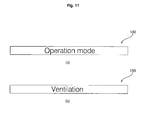
- FIG. 11 is a plan view showing another embodiment in which the setting item is changed from the " operation mode” item to the " ventilation” item in the display unit of FIG. 3 .
- FIG. 12 is a plan view showing another embodiment in which the set value is changed from " cooling” to " dehumidification” in the " operation mode” item in the display unit of FIG. 3 . The following description will be focused on differences from the foregoing embodiments.
- the setting mode enters a simple display mode. Only the image of the setting items is displayed during the input of a manipulation signal for manipulating the setting items from the plurality of function keys, and only the image of the set values is displayed during the input of a manipulation signal for manipulating set values of the setting items from the plurality of function keys.
- the name of an operable setting item is represented in a first image in the setting item display part 181. Referring to FIG. 11(a) , only the " operation mode" item is shown on the entire first display unit 180. That is, with the simple display mode entered, the " operation mode" is displayed in a first image on the first display unit 180.
- FIG. 11(b) illustrates a state in which the setting item is changed from the " operation mode” item to the " ventilation” item. Afterwards, whenever the user presses the first function key 151, the setting item to be selected is sequentially changed.
- the user can move a manipulation target from the selected setting items to an item for selecting a set value by using the second function keys 152. Afterwards, the user selects a specific set value while moving set values of the selected setting item by the third function keys 153.
- the " operation mode" item selected in FIG. 11(a) in order to change the set value from " cooling” to " dehumidification” , the second function keys 152 are manipulated.
- the manipulation target is moved to a screen for selecting a set value.
- FIGs. 12(a) and 12(b) the user changes the set value from " cooling” to " dehumidification” by the third keys 153.
- the first images representing " cooling” and “ dehumidification” are respectively displayed on the entire first display unit 180. Since only the first image representing the set values is in a large size on the first display unit 180, the user can easily check the current manipulation status.
Landscapes
- Engineering & Computer Science (AREA)
- Chemical & Material Sciences (AREA)
- Combustion & Propulsion (AREA)
- Mechanical Engineering (AREA)
- General Engineering & Computer Science (AREA)
- Human Computer Interaction (AREA)
- Air Conditioning Control Device (AREA)
Applications Claiming Priority (2)
| Application Number | Priority Date | Filing Date | Title |
|---|---|---|---|
| KR1020070099259A KR101321542B1 (ko) | 2007-10-02 | 2007-10-02 | 공기조화장치용 제어장치 |
| KR1020070107207A KR101404106B1 (ko) | 2007-10-24 | 2007-10-24 | 공기조화장치용 제어장치 |
Publications (2)
| Publication Number | Publication Date |
|---|---|
| EP2045541A1 true EP2045541A1 (fr) | 2009-04-08 |
| EP2045541B1 EP2045541B1 (fr) | 2015-09-02 |
Family
ID=40220115
Family Applications (1)
| Application Number | Title | Priority Date | Filing Date |
|---|---|---|---|
| EP08251886.1A Ceased EP2045541B1 (fr) | 2007-10-02 | 2008-05-30 | Dispositif de contrôle pour climatiseur |
Country Status (1)
| Country | Link |
|---|---|
| EP (1) | EP2045541B1 (fr) |
Cited By (7)
| Publication number | Priority date | Publication date | Assignee | Title |
|---|---|---|---|---|
| EP2604935A1 (fr) * | 2011-12-13 | 2013-06-19 | Lennox Industries Inc. | Interface utilisateur de système de conditionnement, de chauffage et de ventilation dotée de graphiques d'animation proportionnels et son procédé de fonctionnement |
| EP2604933A1 (fr) * | 2011-12-13 | 2013-06-19 | Lennox Industries Inc. | Interface utilisateur de système de conditionnement, de chauffage et de ventilation dotée d'une fonctionnalité de touche unique et son procédé de fonctionnement |
| EP2604939A1 (fr) * | 2011-12-13 | 2013-06-19 | Lennox Industries Inc. | Interface utilisateur de système de conditionnement, de chauffage et de ventilation dotée de polices modifiables et son procédé de fonctionnement |
| US20160146492A1 (en) * | 2013-11-12 | 2016-05-26 | Mitsubishi Electric Corporation | Remote controller |
| EP3037740A1 (fr) * | 2014-12-19 | 2016-06-29 | Mitsubishi Heavy Industries, Ltd. | Système de conditionnement d'air avec unité d'affichage et de commande et methode d'opération dudite système |
| EP3407616A4 (fr) * | 2016-01-21 | 2019-01-09 | Daikin Industries, Ltd. | Dispositif de télécommande |
| JP2019524526A (ja) * | 2016-07-14 | 2019-09-05 | ベステル エレクトロニク サナイー ベ ティカレト エー.エス. | 空気流偏向のための一体化された手段を有する表示装置 |
Citations (5)
| Publication number | Priority date | Publication date | Assignee | Title |
|---|---|---|---|---|
| EP1092927A2 (fr) * | 1999-10-14 | 2001-04-18 | Sharp Kabushiki Kaisha | Installation de climatisation avec dispositif d'humidification/déshumidification |
| EP1533576A2 (fr) | 2003-11-24 | 2005-05-25 | Lg Electronics Inc. | Dispositif de conditionnement d'air avec une meilleure perception d'utilisateur |
| WO2006121284A2 (fr) * | 2005-05-11 | 2006-11-16 | Lg Electronics Inc. | Conditionneur d'air |
| EP1811241A2 (fr) * | 2006-01-23 | 2007-07-25 | LG Electronics Inc. | Climatiseur et procédé de mise à jour du programme de contrôle destiné à un climatiseur |
| WO2007091825A1 (fr) * | 2006-02-07 | 2007-08-16 | Lg Electronics Inc. | Procédé d'affichage de jour de fête dans un appareil de climatisation |
-
2008
- 2008-05-30 EP EP08251886.1A patent/EP2045541B1/fr not_active Ceased
Patent Citations (5)
| Publication number | Priority date | Publication date | Assignee | Title |
|---|---|---|---|---|
| EP1092927A2 (fr) * | 1999-10-14 | 2001-04-18 | Sharp Kabushiki Kaisha | Installation de climatisation avec dispositif d'humidification/déshumidification |
| EP1533576A2 (fr) | 2003-11-24 | 2005-05-25 | Lg Electronics Inc. | Dispositif de conditionnement d'air avec une meilleure perception d'utilisateur |
| WO2006121284A2 (fr) * | 2005-05-11 | 2006-11-16 | Lg Electronics Inc. | Conditionneur d'air |
| EP1811241A2 (fr) * | 2006-01-23 | 2007-07-25 | LG Electronics Inc. | Climatiseur et procédé de mise à jour du programme de contrôle destiné à un climatiseur |
| WO2007091825A1 (fr) * | 2006-02-07 | 2007-08-16 | Lg Electronics Inc. | Procédé d'affichage de jour de fête dans un appareil de climatisation |
Cited By (10)
| Publication number | Priority date | Publication date | Assignee | Title |
|---|---|---|---|---|
| EP2604935A1 (fr) * | 2011-12-13 | 2013-06-19 | Lennox Industries Inc. | Interface utilisateur de système de conditionnement, de chauffage et de ventilation dotée de graphiques d'animation proportionnels et son procédé de fonctionnement |
| EP2604933A1 (fr) * | 2011-12-13 | 2013-06-19 | Lennox Industries Inc. | Interface utilisateur de système de conditionnement, de chauffage et de ventilation dotée d'une fonctionnalité de touche unique et son procédé de fonctionnement |
| EP2604939A1 (fr) * | 2011-12-13 | 2013-06-19 | Lennox Industries Inc. | Interface utilisateur de système de conditionnement, de chauffage et de ventilation dotée de polices modifiables et son procédé de fonctionnement |
| US8878854B2 (en) | 2011-12-13 | 2014-11-04 | Lennox Industries Inc. | Heating, ventilation and air conditioning system user interface having adjustable fonts and method of operation thereof |
| US20160146492A1 (en) * | 2013-11-12 | 2016-05-26 | Mitsubishi Electric Corporation | Remote controller |
| EP3070412A4 (fr) * | 2013-11-12 | 2017-06-28 | Mitsubishi Electric Corporation | Télécommande |
| EP3037740A1 (fr) * | 2014-12-19 | 2016-06-29 | Mitsubishi Heavy Industries, Ltd. | Système de conditionnement d'air avec unité d'affichage et de commande et methode d'opération dudite système |
| EP3407616A4 (fr) * | 2016-01-21 | 2019-01-09 | Daikin Industries, Ltd. | Dispositif de télécommande |
| US10520907B2 (en) | 2016-01-21 | 2019-12-31 | Daikin Industries, Ltd. | Remote control device |
| JP2019524526A (ja) * | 2016-07-14 | 2019-09-05 | ベステル エレクトロニク サナイー ベ ティカレト エー.エス. | 空気流偏向のための一体化された手段を有する表示装置 |
Also Published As
| Publication number | Publication date |
|---|---|
| EP2045541B1 (fr) | 2015-09-02 |
Similar Documents
| Publication | Publication Date | Title |
|---|---|---|
| EP2045541B1 (fr) | Dispositif de contrôle pour climatiseur | |
| US7997506B2 (en) | Air conditioning system | |
| DE69423204T2 (de) | Mehrzweckbenutzerschnittstelle | |
| US9846531B2 (en) | Integration of building automation systems in a logical graphics display without scale and a geographic display with scale | |
| EP2031318B1 (fr) | Système de climatisation avec manipulation réductible au controle locale et authentification d'usager | |
| US20140058569A1 (en) | Air-conditioning management device, and program | |
| US8655489B2 (en) | Air-conditioning controller | |
| US9964327B2 (en) | Air-conditioning remote controller and air-conditioning system | |
| EP2072922A1 (fr) | Système de climatisation avec changement automatique du mode d'opération dépendant de la température interne | |
| KR20090034094A (ko) | 공기조화장치용 제어장치 | |
| JP2010007887A (ja) | 建造物管理サーバ、建造物管理方法および建造物管理プログラム | |
| JPWO1999034151A1 (ja) | 空調管理情報表示方法および空調管理装置 | |
| JP4870034B2 (ja) | プラント監視制御装置 | |
| EP2604939A1 (fr) | Interface utilisateur de système de conditionnement, de chauffage et de ventilation dotée de polices modifiables et son procédé de fonctionnement | |
| US12007135B2 (en) | Air conditioning system and system controller with display automatically changing language displayed according to user making reservation | |
| KR101404106B1 (ko) | 공기조화장치용 제어장치 | |
| JP5693767B2 (ja) | リモートコントロール装置 | |
| JP6637733B2 (ja) | 空調機管理用画面生成装置、およびこれを利用する空調管理装置、空調機管理用画面生成方法 | |
| KR100941471B1 (ko) | 공기조화기의 제어방법 | |
| JP7110878B2 (ja) | 空気調和機用コントローラ | |
| JP2013102446A (ja) | リモートコントロール装置 | |
| KR20090041601A (ko) | 공기조화장치의 원격제어장치 | |
| KR20090033683A (ko) | 공기조화장치용 제어장치 | |
| JP2000347721A (ja) | プラント監視制御システム | |
| JP2006285373A (ja) | 画面表示方法および情報端末 |
Legal Events
| Date | Code | Title | Description |
|---|---|---|---|
| PUAI | Public reference made under article 153(3) epc to a published international application that has entered the european phase |
Free format text: ORIGINAL CODE: 0009012 |
|
| AK | Designated contracting states |
Kind code of ref document: A1 Designated state(s): AT BE BG CH CY CZ DE DK EE ES FI FR GB GR HR HU IE IS IT LI LT LU LV MC MT NL NO PL PT RO SE SI SK TR |
|
| AX | Request for extension of the european patent |
Extension state: AL BA MK RS |
|
| 17P | Request for examination filed |
Effective date: 20091006 |
|
| AKX | Designation fees paid |
Designated state(s): ES FR IT |
|
| REG | Reference to a national code |
Ref country code: DE Ref legal event code: 8566 |
|
| GRAP | Despatch of communication of intention to grant a patent |
Free format text: ORIGINAL CODE: EPIDOSNIGR1 |
|
| INTG | Intention to grant announced |
Effective date: 20150318 |
|
| GRAS | Grant fee paid |
Free format text: ORIGINAL CODE: EPIDOSNIGR3 |
|
| GRAA | (expected) grant |
Free format text: ORIGINAL CODE: 0009210 |
|
| AK | Designated contracting states |
Kind code of ref document: B1 Designated state(s): ES FR IT |
|
| PG25 | Lapsed in a contracting state [announced via postgrant information from national office to epo] |
Ref country code: ES Free format text: LAPSE BECAUSE OF FAILURE TO SUBMIT A TRANSLATION OF THE DESCRIPTION OR TO PAY THE FEE WITHIN THE PRESCRIBED TIME-LIMIT Effective date: 20150902 |
|
| REG | Reference to a national code |
Ref country code: FR Ref legal event code: PLFP Year of fee payment: 9 |
|
| PLBE | No opposition filed within time limit |
Free format text: ORIGINAL CODE: 0009261 |
|
| STAA | Information on the status of an ep patent application or granted ep patent |
Free format text: STATUS: NO OPPOSITION FILED WITHIN TIME LIMIT |
|
| 26N | No opposition filed |
Effective date: 20160603 |
|
| REG | Reference to a national code |
Ref country code: FR Ref legal event code: PLFP Year of fee payment: 10 |
|
| REG | Reference to a national code |
Ref country code: FR Ref legal event code: PLFP Year of fee payment: 11 |
|
| PGFP | Annual fee paid to national office [announced via postgrant information from national office to epo] |
Ref country code: IT Payment date: 20190514 Year of fee payment: 12 |
|
| PGFP | Annual fee paid to national office [announced via postgrant information from national office to epo] |
Ref country code: FR Payment date: 20190410 Year of fee payment: 12 |
|
| PG25 | Lapsed in a contracting state [announced via postgrant information from national office to epo] |
Ref country code: FR Free format text: LAPSE BECAUSE OF NON-PAYMENT OF DUE FEES Effective date: 20200531 |
|
| PG25 | Lapsed in a contracting state [announced via postgrant information from national office to epo] |
Ref country code: IT Free format text: LAPSE BECAUSE OF NON-PAYMENT OF DUE FEES Effective date: 20200530 |