EP2045588A2 - Waage mit hoher Kapazität und hoher Auflösung - Google Patents
Waage mit hoher Kapazität und hoher Auflösung Download PDFInfo
- Publication number
- EP2045588A2 EP2045588A2 EP08165787A EP08165787A EP2045588A2 EP 2045588 A2 EP2045588 A2 EP 2045588A2 EP 08165787 A EP08165787 A EP 08165787A EP 08165787 A EP08165787 A EP 08165787A EP 2045588 A2 EP2045588 A2 EP 2045588A2
- Authority
- EP
- European Patent Office
- Prior art keywords
- weight
- sensor
- scale
- signal
- load cell
- Prior art date
- Legal status (The legal status is an assumption and is not a legal conclusion. Google has not performed a legal analysis and makes no representation as to the accuracy of the status listed.)
- Withdrawn
Links
- 230000007246 mechanism Effects 0.000 claims abstract description 53
- 230000001939 inductive effect Effects 0.000 claims description 21
- 238000000034 method Methods 0.000 claims description 15
- 230000004044 response Effects 0.000 claims description 14
- 239000000758 substrate Substances 0.000 claims description 8
- 230000035945 sensitivity Effects 0.000 claims description 6
- 230000000694 effects Effects 0.000 claims description 4
- 230000003287 optical effect Effects 0.000 claims description 4
- 238000006073 displacement reaction Methods 0.000 claims description 3
- 238000012546 transfer Methods 0.000 abstract description 16
- 238000005259 measurement Methods 0.000 description 37
- 238000010586 diagram Methods 0.000 description 17
- 238000001914 filtration Methods 0.000 description 8
- 238000006386 neutralization reaction Methods 0.000 description 6
- 230000001965 increasing effect Effects 0.000 description 5
- 230000005672 electromagnetic field Effects 0.000 description 4
- 230000003247 decreasing effect Effects 0.000 description 3
- 238000005516 engineering process Methods 0.000 description 3
- 230000008569 process Effects 0.000 description 3
- 238000013459 approach Methods 0.000 description 2
- 230000008901 benefit Effects 0.000 description 2
- 239000013590 bulk material Substances 0.000 description 2
- 230000008878 coupling Effects 0.000 description 2
- 238000010168 coupling process Methods 0.000 description 2
- 238000005859 coupling reaction Methods 0.000 description 2
- 230000006870 function Effects 0.000 description 2
- 230000036541 health Effects 0.000 description 2
- 230000010287 polarization Effects 0.000 description 2
- 238000005303 weighing Methods 0.000 description 2
- 239000003990 capacitor Substances 0.000 description 1
- 230000000295 complement effect Effects 0.000 description 1
- 238000001514 detection method Methods 0.000 description 1
- 230000006872 improvement Effects 0.000 description 1
- 229910044991 metal oxide Inorganic materials 0.000 description 1
- 150000004706 metal oxides Chemical class 0.000 description 1
- 238000012986 modification Methods 0.000 description 1
- 230000004048 modification Effects 0.000 description 1
- 230000003472 neutralizing effect Effects 0.000 description 1
- 230000009467 reduction Effects 0.000 description 1
- 239000004065 semiconductor Substances 0.000 description 1
- 230000002123 temporal effect Effects 0.000 description 1
- 238000013519 translation Methods 0.000 description 1
Images


Classifications
-
- G—PHYSICS
- G01—MEASURING; TESTING
- G01G—WEIGHING
- G01G19/00—Weighing apparatus or methods adapted for special purposes not provided for in the preceding groups
- G01G19/02—Weighing apparatus or methods adapted for special purposes not provided for in the preceding groups for weighing wheeled or rolling bodies, e.g. vehicles
- G01G19/021—Weighing apparatus or methods adapted for special purposes not provided for in the preceding groups for weighing wheeled or rolling bodies, e.g. vehicles having electrical weight-sensitive devices
-
- G—PHYSICS
- G01—MEASURING; TESTING
- G01G—WEIGHING
- G01G1/00—Weighing apparatus involving the use of a counterweight or other counterbalancing mass
- G01G1/18—Balances involving the use of a pivoted beam, i.e. beam balances
- G01G1/24—Platform-type scales, i.e. having the pans carried above the beam
- G01G1/243—Platform-type scales, i.e. having the pans carried above the beam having pans carried above the beam
-
- G—PHYSICS
- G01—MEASURING; TESTING
- G01G—WEIGHING
- G01G19/00—Weighing apparatus or methods adapted for special purposes not provided for in the preceding groups
- G01G19/002—Weighing apparatus or methods adapted for special purposes not provided for in the preceding groups for postal parcels and letters
-
- G—PHYSICS
- G01—MEASURING; TESTING
- G01G—WEIGHING
- G01G19/00—Weighing apparatus or methods adapted for special purposes not provided for in the preceding groups
- G01G19/40—Weighing apparatus or methods adapted for special purposes not provided for in the preceding groups with provisions for indicating, recording, or computing price or other quantities dependent on the weight
- G01G19/413—Weighing apparatus or methods adapted for special purposes not provided for in the preceding groups with provisions for indicating, recording, or computing price or other quantities dependent on the weight using electromechanical or electronic computing means
- G01G19/414—Weighing apparatus or methods adapted for special purposes not provided for in the preceding groups with provisions for indicating, recording, or computing price or other quantities dependent on the weight using electromechanical or electronic computing means using electronic computing means only
- G01G19/4146—Weighing apparatus or methods adapted for special purposes not provided for in the preceding groups with provisions for indicating, recording, or computing price or other quantities dependent on the weight using electromechanical or electronic computing means using electronic computing means only for controlling caloric intake, e.g. diet control
-
- G—PHYSICS
- G01—MEASURING; TESTING
- G01G—WEIGHING
- G01G23/00—Auxiliary devices for weighing apparatus
- G01G23/005—Means for preventing overload
-
- G—PHYSICS
- G01—MEASURING; TESTING
- G01G—WEIGHING
- G01G23/00—Auxiliary devices for weighing apparatus
- G01G23/02—Relieving mechanisms; Arrestment mechanisms
-
- G—PHYSICS
- G01—MEASURING; TESTING
- G01G—WEIGHING
- G01G3/00—Weighing apparatus characterised by the use of elastically-deformable members, e.g. spring balances
- G01G3/12—Weighing apparatus characterised by the use of elastically-deformable members, e.g. spring balances wherein the weighing element is in the form of a solid body stressed by pressure or tension during weighing
- G01G3/14—Weighing apparatus characterised by the use of elastically-deformable members, e.g. spring balances wherein the weighing element is in the form of a solid body stressed by pressure or tension during weighing measuring variations of electrical resistance
- G01G3/1402—Special supports with preselected places to mount the resistance strain gauges; Mounting of supports
- G01G3/1404—Special supports with preselected places to mount the resistance strain gauges; Mounting of supports combined with means to connect the strain gauges on electrical bridges
-
- G—PHYSICS
- G01—MEASURING; TESTING
- G01G—WEIGHING
- G01G7/00—Weighing apparatus wherein the balancing is effected by magnetic, electromagnetic, or electrostatic action, or by means not provided for in the preceding groups
- G01G7/02—Weighing apparatus wherein the balancing is effected by magnetic, electromagnetic, or electrostatic action, or by means not provided for in the preceding groups by electromagnetic action
- G01G7/04—Weighing apparatus wherein the balancing is effected by magnetic, electromagnetic, or electrostatic action, or by means not provided for in the preceding groups by electromagnetic action with means for regulating the current to solenoids
Definitions
- Embodiments of the present invention generally relate to scales. More particularly, embodiments of the present invention relate to scales having the ability to weigh very heavy objects to a high degree of resolution.
- Typical scales are passive measuring instruments that can be used in a wide variety of environments such as automotive, health provider and mail handling environments. For example, modern day postal operations may involve determining package handling and routing procedures, as well as postage, which are all a function of the size and weight of the package. In addition, the size and weight of the packages being processed can vary greatly in a particular setting. Indeed, it may not be uncommon for a given mail handling facility to be required to determine the weight of 0.25 oz letters, as well as 100 lb packages and letter bins.
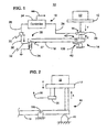
- FIG. 1 is a diagram of a scale in which a controller generates weight measurements according to an embodiment of the present invention
- FIG. 2 is a diagram of a force coupling arrangement of a scale according to an embodiment of the present invention
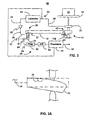
- FIG. 3A is a diagram of a scale in which a weight calculation circuit generates weight measurements according to an embodiment of the present invention
- Figure 3B is a diagram of a sensor flexing under a load in accordance with an embodiment of the present invention.
- FIG. 4A is a diagram of a controller having digital filtering and measurement functionality according to an embodiment of the present invention.
- FIG. 4B is a diagram of a controller having digital measurement and analog filtering functionality according to an embodiment of the present invention.
- FIG. 5A is a diagram of a controller having digital filtering functionality according to an embodiment of the present invention.
- FIG. 5B is a diagram of a controller having analog filtering functionality according to an embodiment of the present invention.
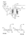
- FIG. 6 is a schematic diagram of an analog filter according to an embodiment of the present invention.
- FIG. 7 are plots of a load cell voltage curve and a power amplifier drive signal according to embodiments of the present invention.
- FIG. 8 is a diagram of an enlarged view of an electromagnet configuration according to an embodiment of the present invention.
- FIG. 9A is a diagram of a counterforce end of a lever having a pivot point that is laterally located between a driving end of the lever and a load cell contact point according to an embodiment of the present invention
- FIG. 9B is a diagram of a counterforce end of a lever having a load cell contact point that is laterally located between a driving end of the lever and a pivot point of the lever according to an embodiment of the present invention
- FIG. 10A is a flowchart of a method of weighing an object upon neutralization of a load according to an embodiment of the present invention.
- FIG. 10B is a flowchart of a method of weighing an object prior to neutralization of a load according to an embodiment of the present invention.
- Embodiments of the present invention provide for an active scale including a low capacity sensing mechanism operatively coupled to a support platform or member, wherein the low capacity sensing mechanism may detect movement resulting from a weight of an object, or load, placed upon the support platform.
- a low capacity sensing mechanism is a load cell including four strain gauges arranged as a Wheatstone bridge.
- a force transfer mechanism is operatively coupled to the low capacity sensing mechanism and responsive to an amount of load placed upon the scale, thereby enabling the scale to weigh loads in excess of a capacity of the low capacity sensing mechanism.
- the transfer mechanism enables measurement of weight exceeding the capacity of the low capacity sensing mechanism to a minor division resolution associated with the low capacity sensing mechanism.
- Embodiments of the transfer mechanism can include a lever assembly and an electromagnetic actuator.
- the lever assembly includes a lever that is operatively coupled to at least one of the support member and the low capacity sensing mechanism.
- the lever assembly is responsive to lever movement resulting from placement of the object upon the support member to reduce the effect of the weight upon the low capacity sensing mechanism.
- an electromagnet actuator is operatively coupled to the low capacity sensing mechanism and the lever to reduce or neutralize the load upon the low capacity sensing mechanism via the lever.
- the scale is a postal scale, incorporated within a postal metering device. It will be appreciated that details pertaining to operation of a postal metering device are known, and will not be presented herein. Embodiments of the scale may therefore have a weight capacity-to-resolution ratio of four or more orders of magnitude. For example, the scale may accurately weigh an object on the order of 10 3 grams to an accuracy of 10 -1 grams.
- FIG. 1 shows an active scale 10 generally having a support member 12, a low capacity sensing mechanism such as a sensor 20, and a force transfer mechanism that may include a force transfer assembly 14 (also herein referred to as a “lever assembly”) and an electromagnetic actuator 16 (also herein referred to as an "electromechanical force inducing mechanism").
- the illustrated scale 10 may be used in a wide variety of applications such as postal applications, automotive applications, health care provider applications, etc., and provides a relatively high level of resolution (e.g., minor division resolution of 1/32 oz) while maintaining the ability to weigh relatively heavy objects (e.g., 100 lbs).
- the lever assembly 14 of the transfer mechanism can include a force transmitter 18 (also herein referred to as a "lever"), wherein the sensor 20 is able to detect movement of the support 12 associated with a weight of an object 22 disposed upon the support 12. It will be appreciated that movement of the support 12 may result in a corresponding movement of the lever 18.
- a force transmitter 18 also herein referred to as a "lever”
- the illustrated electromagnetic actuator 16 is operatively coupled to the sensor 20 and the lever 18 to neutralize the load on the sensor 20.
- the scale 10 can weigh very heavy objects such as vehicles, humans, and large bins of mail.
- the sensor 20 having a high sensitivity, the illustrated scale 10 is able to detect slight load changes, such as the addition or removal of a single mailing envelope for example.
- the active scale 10 provides greater capacity and resolution than conventional passive measuring scales.
- a ratio of the scale's weight capacity to its resolution may be limited only by frictional forces in components such as bearings at pivot 37.
- the illustrated electromagnetic actuator 16 includes a controller 24, such as a servo controller, that is configured to generate a drive signal 26 based upon a feedback signal 28 (also herein referred to as a "sensor signal") from the sensor 20, wherein the feedback signal 28 is responsive to and indicative of at least one of movement of the lever 18 and detection, via the sensor 20, of the weight of the object 22 placed upon the support 12.
- the drive signal 26 and feedback signal 28 are analog signals.
- the illustrated electromagnetic actuator 16 also includes a power amplifier 30, and a force inducing mechanism such as a solenoid having a coil 32 and a plunger 34.
- the power amplifier 30 may amplify the drive signal 26 from the controller 24 and provide the amplified drive signal 36 to the coil 32.
- the illustrated coil 32 produces an electromagnetic field in response to the amplified drive signal 36.
- the plunger 34 may be coupled to a driving end 38 of the lever 18 via pivot 37 and is responsive to the electromagnetic field produced by the current in the coil 32 to translate in a direction A at the driving end 38. Translation of the plunger 34 thereby causes rotation of the lever 18 about pivot 106 and generation of a force in a direction X at a counterforce end 42 of the lever 18. The force in the direction X opposes a force in a direction Y that results from the weight of the object 22 upon the support 12. For example, if additional weight (e.g., another letter) is added to the support member 12, the increased load results in an increased feedback signal 28 generated by the sensor 20, thereby notifying the controller 24 of the increased load.
- additional weight e.g., another letter
- the controller 24 may then increase the current to the coil 32, forcing the driving end 38 of the lever 18 downward about pivot 106 and the counterforce end 42 upward to effectively neutralize the additional weight placed upon support 12. Similarly, if weight is removed from the support member 12, the decreased load on the sensor 20 results in a reduced feedback signal 28 and thus the controller 24 is notified of the associated reduced load, and may reduce the current to coil 32 appropriately. In either instance, the illustrated controller 24 is also configured to generate a weight measurement 44.
- the weight measurement 44 may be generated: upon neutralization of the weight of the object 22 relative to the sensor 20; or as the weight of the object relative to the senor 20 approaches neutralization.
- the controller 24 may adjust the drive signal 26 current until the weight of the object 22 upon the sensor 20 is approximately zero, and calculate the weight measurement 44 based on the drive signal 26 current required to neutralize the load relative to the sensor 20.
- This example may be useful in configurations in which the sensor 20 indicates a zero "steady-state" condition corresponding to neutralization of the total weight of the object 22, but does not produce weight measurements.
- the controller 24 may generate the weight measurement 44 based on the drive signal 26 and the feedback signal 28 as the controller 24 makes drive signal 26 adjustments.
- the sensor 20 is a device such as a load cell 99 for example, that is able to produce intermediate weight measurement signals that may be summed with contemporaneous weight signals resulting from calculation based upon the drive signal 26.
- one embodiment of the sensor 20 may include a strain gauge load cell 99, responsive to deformation of sensor 20 bulk material, disposed between and adjacent to the support member 12 and the counterforce end 42 of the lever 18 (e.g. shown disposed to the left of support member 12 and counterforce end 42 in FIG. 1 ).
- the force applied in the direction X via the counterforce end 42 effectively neutralizes or reduces sensor 20 bulk material deformation, as influenced by the weight of object 22 applied in the direction Y upon the load cell 99.
- An embodiment of scale 10 includes a stop 40 to limit displacement of the support 12 via counterforce end 42 of the lever 18.
- use of the load cell 99 to provide intermediate weight calculations is contemplated to enable faster operation of the scale 10 to provide expedient weight measurements.
- a load cell 99 as a sensor
- the scope of the invention is not so limited, and is contemplated to include alternate sensors, such as optical, linear variable differential transformer (LVDT), micro-electro-mechanical system (MEMS), and piezoelectric sensors. It will be further appreciated that some of these sensors, such as LVDT and optical sensors for example, are position sensors and primarily sense displacement in response to applied force.
- actuator 16 uses a solenoid to neutralize the load
- other technologies such as a stepper motor, a linear motor, or other electromechanical force inducing mechanisms may be used without parting from the spirit and scope of embodiments described herein.
- FIG. 2 depicts an embodiment having the support member 12 operatively coupled to the sensor 20 and the counterforce end 42 of the lever 18 operatively coupled to the support member 12 and having pivot 106.
- the arrangement depicted in FIG. 2 functions as described above to effectively reduce or neutralize the weight of the object 22 upon sensor 20. It will be appreciated that use of the arrangement of FIG. 2 can reduce total force applied to sensor 20 to accommodate use of alternate sensor 20 technologies, such as a piezoelectric sensor, for example.
- FIG. 3A depicts an embodiment of a scale 46 including a weight calculation circuit 48 that generates a weight measurement 50.
- the illustrated weight calculation circuit 48 has an interface with an electromagnetic actuator 52 (also herein referred to as an "electromechanical force inducing mechanism"), which includes a controller 54, power amplifier 30, coil 32, and plunger 34.
- the interface is a current sensor 56 that detects the voltage across a relatively small known resistance that is in series with the coil 32 in order to measure an actuation current flowing through the coil 32 in response to provision of the amplified drive signal 36.
- the result may be an analog measurement signal 58 that is proportional to the amount of force required to neutralize the load upon sensor 20.
- the illustrated circuit 48 also includes an analog filter 60 to filter the analog measurement signal 58 and an analog to digital (A/D) converter 62 to convert the filtered measurement signal into a digital measurement signal.
- a processor 64 may be used to determine the weight of the object 22 based on the digital measurement signal and generate the weight measurement 50. In particular, the processor 64 may perform a running average calculation to enhance accuracy. The processor 64 may also generate the weight measurement 50 based on the feedback signal 28 to the extent that the sensor 20 is able to produce weight measurements and/or the scale 46 is not in compensation mode (using the sensor 20 indicative of the zero "steady-state" condition), as already discussed.
- the weight of object 22 can be determined by controller 24, 54 or processor 64 detecting that sensor 20 is, or will be, operating outside of its weight range under the load of the object 22.
- sensor 20 can be a load cell including the strain gauge 99 as shown in Figure 1 .
- the strain gauge 99 is mounted on a substrate that flexes under the weight of an object 22 placed on platform 12. The range over which the substrate may flex, and the strain gauge 99 provides desired accuracy, is finite.
- FIG. 3B depicts such flexure of the sensor 20 including the strain gauge 99 in response to application of the object 22 upon platform 12.
- Controller 24, 54 can be programmed to detect when the load cell is at or approaching the limit of its weight range based upon the feedback signal 28 from the load cell 20 that indicates the substrate is flexing beyond a certain predetermined limit. Upon detecting such a condition, controller 24, 54 can drive current to the electromechanical force inducing mechanism 16, 52 to produce a counterforce at the counterforce end 42 of the lever 18 underneath load cell 20, reversing the flexion of the substrate and restoring the load cell 20 to operation within its weight range.
- Processor 64 may then calculate the weight of the object 22 based upon the amount of current driven to the electromechanical force inducing mechanism 16, 52and a signal received from the load cell.
- the current driven to the electromechanical force inducing mechanism 16, 52 need only be applied within the tolerance required to restore the load cell to operation anywhere within its weight range. In this way, a more accurate and expedient measurement may be made of the weight of the object 22.
- the sensitivity of the measurement made by the load cell when operating within its weight range can be combined with the known amount of current driven to the electromechanical force inducing mechanism 16, 52 to produce an accurate weight measurement of object 22.
- FIG. 4A depicts a schematic diagram of one example of the controller 24 ( FIG. 1 ) in greater detail.
- the controller 24 includes a pre-amplifier 68 that is configured to amplify the feedback signal 28 from the sensor 20 ( FIG. 1 ) and an A/D converter 66 that converts the amplified feedback signal into a digital feedback signal 71.
- a processor 70 determines and generates a digital drive signal 72 based on the digital feedback signal 71, wherein a digital to analog (D/A) converter 73 converts the digital drive signal 72 into the analog drive signal 26 already discussed.
- the illustrated processor 70 also includes filtering logic 74 that filters the digital feedback signal 71 and measurement logic 76, thereby determining the weight of the object 22 ( FIG. 1 ) based upon the digital drive signal 72 and/or the digital feedback signal 71. As previously discussed, the weight is then provided via weight measurement 44.
- FIG. 4B depicts a schematic diagram of an embodiment of an alternate controller 25.
- Controller 25 includes an analog filter 80 that filters the amplified feedback signal from the pre-amplifier 68 and provides the filtered feedback signal to the A/D converter 66.
- a processor 78 determines and generates the digital drive signal 72 based on a digital feedback signal 75.
- Processor 78 uses measurement logic 76 to determine the weight of the object 22.
- Use of the analog filter 80 eliminates the digital filtering logic required by controller 24 depicted in FIG. 4A .
- FIG. 5A depicts a schematic diagram of an embodiment of controller 54 ( FIG. 3 ) in greater detail.
- the controller 54 has a processor 82 that includes filtering logic 74 to filter the digital feedback signal 71, but excludes measurement logic because the weight measurement is made by the weight measurement circuit 48 ( FIG. 3 ).
- FIG. 5B depicts a schematic diagram of an embodiment of an alternate controller 84 in which a processor 86 determines and generates the digital drive signal 72, but does not filter the feedback signal 28 or determine the weight of the object 22.
- FIG. 6 depicts one example of the low pass filter 60 that may be used to process signals from the electromagnetic actuator current sensor 56 ( FIG. 3 ).
- analog measurement signal 58 exhibits slight variability due to vibration and/or other factors as shown in input trace 88.
- An amplifier 90, resistor 92, and capacitor 94 combination form a low pass filter and yield a filtered measurement signal with less variation as reflected in an output trace 96.
- Other possible implementations of this and other filtering processes can include transforms such as Laplace transforms.
- a load cell voltage plot 98 and a drive signal plot 100 illustrate an example of scale operation as described above.
- a stack of mail may be placed on the scale 10, 46 ( FIGs. 1 and 3A ), causing a voltage of the sensor (V LC ) (such as load cell 99 for example), also herein referred to as the load cell voltage, to grow to a peak 102 at time t 1 .
- V LC voltage of the sensor
- V D a voltage of the drive signal 26
- V D a voltage of the drive signal 26
- the drive signal voltage levels off (t 2 ) to a steady state value.
- a letter is removed from the pile, which causes the drive signal voltage to reduce and thereby return the load cell voltage towards zero offset, where the drive signal voltage will level off.
- another letter is removed from the pile, which causes another reduction of the drive signal voltage to thereby return the load cell voltage towards zero offset.
- the drive signal voltage remains at a constant or substantially constant value once the load upon the sensor 20 has been neutralized.
- FIG. 8 depicts a schematic diagram of an embodiment of a solenoid having a coil 32 and plunger 34.
- the plunger 34 is responsive to the electromagnetic field produced by the actuation current flowing through the coil 32 to translate.
- the plunger 34 is pivotally coupled to the driving end 38 of the lever 18 via pivot 37. Pivot 37 allows plunger 34 to translate in a generally vertical orientation while lever 18 rotates about pivot 106 (best seen with reference to FIG. 1 ).
- the plunger 34 may be a high strength magnet plunger having a generally vertical magnetic polarization 104.
- a small current sensing resistor (not shown) may also be used as an interface between the weight calculation circuit 48 ( FIG. 3 ) and the coil 32.
- other solutions such as stepper motors, linear motors, and other electromagnetic force inducing mechanisms may also be used.
- FIGs. 9A and 9B depict various configurations of the position of the pivot 106 relative to the lever 18.
- FIG. 9A illustrates an example in which the lever 18 has pivot point 106 laterally located between the driving end 38 of the lever 18 and a support member interface point 108
- FIG. 9B illustrates an example in which lever 18 has a support member interface point 108 that is laterally located between the driving end 38 of the lever 18 and the pivot point 106 of the lever18.
- alternate configurations of the position of the pivot 106 relative to the lever 18 can accommodate alternate directions of force applied to the driving end 38 as well as to provide an appropriate multiplication ratio of force as applied to the driving end 38 and by support member interface point 108.
- the methods 112 and 126 may be implemented in a controller and/or weight calculation circuit as a set of processor-executable instructions stored in any suitable computer-readable media, such as read only memory (ROM), random access memory (RAM), electrically erasable programmable ROM (EEPROM), flash memory, etc., as fixed functionality hardware such as an embedded microcontroller, application specific integrated circuit (ASIC), etc. using complementary metal oxide semiconductor (CMOS) technology or transistor-transistor-logic (TTL), or any combination thereof.
- CMOS complementary metal oxide semiconductor
- TTL transistor-transistor-logic
- the scale may be operated in response to a feedback signal indicative of a load corresponding to an object on a support member of the scale.
- weight measurements are made based on the amount of force required to neutralize the load.
- process block 113 provides for receiving the feedback signal 28 and block 114 provides for determining whether the load is positive (e.g., pushing the counterforce end 42 of the lever 18 down as depicted in FIGs 1 and 3 , such that the weight of the object 22 exceeds the capacity of the sensor 20). If so, the drive signal 26 current/voltage is increased at block 116. It is understood that depending upon the direction of the electromagnetic field and plunger 34 polarization, the positive/negative and/or increasing/decreasing designations may be reversed without parting from the spirit and scope of the embodiments described.
- block 118 provides for determining whether the load is negative (e.g., application of a force by the counterforce end 42 of the lever 18 that exceeds the force exerted upon sensor 20 by the support member 12). In response to determining that the load is negative, the drive signal 26 current/voltage is decreased at the illustrated block 120. Otherwise, it can be determined that the load has been neutralized and the weight of the object can be calculated at block 122 based on the drive signal 26. Thus, the illustrated example makes weight calculations based on the drive signal 26 once the load upon the sensor 20 has been neutralized. As already discussed, the weight determination may be based on other factors such as the amount of current sensed in the electromagnetic actuator 16, 52. Block 124 determines whether to continue taking readings and compensating for load variations.
- Block 124 determines whether to continue taking readings and compensating for load variations.
- FIG. 10B shows an alternative method 126 in which weight calculations may be made before the load has been fully neutralized.
- the illustrated example is particularly useful for applications using a sensor 20 incorporating the load cell 99, which may be capable of generating feedback signals that are indicative of weight.
- block 113 provides for receiving the feedback signal 28 and block 128 provides for determining whether the sensor 20 (e.g., load cell) is within its operational range based on the feedback signal 28. For example, if the load cell 99 is rated at a maximum load of 5 lbs and the feedback signal 28 indicates a weight of 3 1/2 lbs, it can be determined that the load cell 99 is functioning within the operational range. If, however, the load cell 99 indicates a weight of 5 lbs (or overload/error), it can be determined that the load cell 99 is outside the operational range.
- the sensor 20 e.g., load cell
- illustrated block 130 provides for adjusting a drive signal 26 current of a transfer mechanism (e.g., actuator and/or lever assembly) toward the middle of the operational range, and illustrated block 132 provides for setting a compensation flag to indicate that the transfer mechanism is in compensation mode.
- the compensation flag may be a bit stored in memory, wherein the value of the bit indicates whether the transfer mechanism is compensating for the load cell 99.
- the weight of the object 22 may be calculated at block 134 based on the drive signal 26 current.
- illustrated block 136 provides for determining whether the transfer mechanism is in compensation mode. Thus, the determination at block 136 may be made by checking the aforementioned compensation flag. If the transfer mechanism is not in compensation mode, illustrated block 138 provides for clearing the compensation flag, and illustrated block 140 provides for calculating the weight of the object 22 based on the feedback signal 28. If the transfer mechanism is in compensation mode, the weight of the object 22 may be calculated at block 142 based on the drive signal 26 current and the feedback signal 28. In particular, the weight calculated from the drive signal 26 current may be summed with the weight indicated by the feedback signal 28 to obtain an "intermediate" weight while the transfer mechanism works toward neutralizing the load. It will be appreciated that such an intermediate weight may be provided more quickly than the weight calculations described above, with reference to FIG. 10A , following neutralization of the load.
- Embodiments described herein therefore provide a relatively high level of resolution (e.g., minor division resolution of 1/32 oz) while maintaining the ability to weigh relatively heavy objects (e.g., 100 lbs).
- a ratio of weight capacity-to-resolution can be 51,200:1, which represents four orders of magnitude - a substantial improvement over certain conventional approaches.
- Other advantages, including but not limited to, greater speed, reduced cost and enhanced scale adaptability may also be obtained from the techniques discussed herein.
- scale 10 facilitates a method for measuring the weight of an object 22.
- the method includes receiving the feedback signal 28 from the sensor 20.
- the controller 24, 54 drives current, represented as the drive signal 26, to the electromechanical force inducing mechanism 16, 52.
- the driven current thereby generates a counterforce to the weight of the object 22, such that the weight of the object 22 upon the sensor 20 is within the sensitivity range thereof.
- at least one of the controller 24, and the processor 64 calculates the weight of the object 22 based upon a summation of an amount of the driven current and the feedback signal 28 received from the sensor operating within the weight range.
- connection means any type of relationship, direct or indirect, between the components in question, and may apply to electrical, mechanical, RF, optical or other couplings, unless otherwise indicated.
- any uses of the term “first”, “second”, and so on herein are only to facilitate discussion, and do not necessarily infer any type of temporal or chronological relationship.
Landscapes
- Physics & Mathematics (AREA)
- General Physics & Mathematics (AREA)
- Engineering & Computer Science (AREA)
- Mathematical Physics (AREA)
- Theoretical Computer Science (AREA)
- Electromagnetism (AREA)
- Measurement Of Force In General (AREA)
- Length Measuring Devices With Unspecified Measuring Means (AREA)
Applications Claiming Priority (2)
| Application Number | Priority Date | Filing Date | Title |
|---|---|---|---|
| US11/867,968 US7569779B2 (en) | 2007-10-05 | 2007-10-05 | High capacity and high resolution scale |
| US12/188,516 US7989714B2 (en) | 2007-10-05 | 2008-08-08 | High capacity and high resolution scale |
Publications (2)
| Publication Number | Publication Date |
|---|---|
| EP2045588A2 true EP2045588A2 (de) | 2009-04-08 |
| EP2045588A3 EP2045588A3 (de) | 2011-07-13 |
Family
ID=40078198
Family Applications (1)
| Application Number | Title | Priority Date | Filing Date |
|---|---|---|---|
| EP08165787A Withdrawn EP2045588A3 (de) | 2007-10-05 | 2008-10-02 | Waage mit hoher Kapazität und hoher Auflösung |
Country Status (3)
| Country | Link |
|---|---|
| US (1) | US7989714B2 (de) |
| EP (1) | EP2045588A3 (de) |
| CA (1) | CA2640351A1 (de) |
Families Citing this family (17)
| Publication number | Priority date | Publication date | Assignee | Title |
|---|---|---|---|---|
| WO2006000237A1 (en) * | 2004-06-23 | 2006-01-05 | Ecolab Inc. | Method for multiple dosage of liquid products, dosing appartus and dosing system |
| US8277745B2 (en) | 2007-05-02 | 2012-10-02 | Ecolab Inc. | Interchangeable load cell assemblies |
| FR2916271B1 (fr) * | 2007-05-14 | 2009-08-28 | St Microelectronics Sa | Circuit electronique permettant la mesure de masse de materiau biologique et procede de fabrication |
| US7694589B2 (en) * | 2007-12-12 | 2010-04-13 | Ecolab Inc. | Low and empty product detection using load cell and load cell bracket |
| USRE48951E1 (en) | 2015-08-05 | 2022-03-01 | Ecolab Usa Inc. | Hand hygiene compliance monitoring |
| US9102509B2 (en) | 2009-09-25 | 2015-08-11 | Ecolab Inc. | Make-up dispense in a mass based dispensing system |
| US9051163B2 (en) * | 2009-10-06 | 2015-06-09 | Ecolab Inc. | Automatic calibration of chemical product dispense systems |
| US8511512B2 (en) * | 2010-01-07 | 2013-08-20 | Ecolab Usa Inc. | Impact load protection for mass-based product dispensers |
| RU2015133464A (ru) * | 2013-01-11 | 2017-02-17 | Тагнэтикс, Инк. | Датчик отсутствия товаров |
| WO2014179189A1 (en) | 2013-04-30 | 2014-11-06 | Tagnetics, Inc. | Lighted mounting apparatus |
| US9562802B2 (en) | 2013-07-22 | 2017-02-07 | Illinois Tool Works Inc. | Flex circuit interface for strain gauges |
| GB201315715D0 (en) * | 2013-09-04 | 2013-10-16 | Metryx Ltd | Method and device for determining information relating to the mass of a semiconductor wafer |
| US10209121B2 (en) * | 2014-06-26 | 2019-02-19 | Luca Drocco | Multiple weighing scale |
| JP6600756B2 (ja) | 2015-11-30 | 2019-10-30 | リンク エンジニアリング カンパニー | 高荷重高分解能計装スピンドル又はロードセル |
| CN110383355B (zh) | 2017-03-07 | 2021-08-27 | 埃科莱布美国股份有限公司 | 用于手部卫生分配器的监测模块 |
| US10529219B2 (en) | 2017-11-10 | 2020-01-07 | Ecolab Usa Inc. | Hand hygiene compliance monitoring |
| EP3900307A1 (de) | 2018-12-20 | 2021-10-27 | Ecolab USA, Inc. | Bidirektionale netzwerkkommunikation mit adaptiver route |
Family Cites Families (20)
| Publication number | Priority date | Publication date | Assignee | Title |
|---|---|---|---|---|
| US3120754A (en) * | 1960-02-12 | 1964-02-11 | Lebow Associates Inc | Overload protector |
| US3791467A (en) * | 1971-11-12 | 1974-02-12 | B Swersey | Scale having a restrained movable balancing member |
| CH580803A5 (de) * | 1975-02-04 | 1976-10-15 | Mettler Instrumente Ag | |
| CH645463A5 (de) * | 1980-06-06 | 1984-09-28 | Mettler Instrumente Ag | Waage mit elektromagnetischer kraftkompensation. |
| US4375243A (en) * | 1981-03-30 | 1983-03-01 | Doll W Gary | Wide range high accuracy weighing and counting scale |
| US4554987A (en) * | 1983-08-29 | 1985-11-26 | Dillon Benny N | Self-aligning scale assembly and method |
| JPS6196422A (ja) * | 1984-10-17 | 1986-05-15 | Tokyo Electric Co Ltd | マルチレンジロ−ドセル秤 |
| JPS61260124A (ja) * | 1985-05-15 | 1986-11-18 | Tokyo Electric Co Ltd | マルチレンジロ−ドセル秤 |
| JPH0638055B2 (ja) * | 1985-09-17 | 1994-05-18 | 東京電気株式会社 | マルチレンジロ−ドセル秤の計量方法 |
| US4771314A (en) * | 1986-12-29 | 1988-09-13 | Xerox Corporation | Developer apparatus for a highlight printing apparatus |
| DE4001614A1 (de) * | 1990-01-20 | 1991-07-25 | Bosch Gmbh Robert | Kompensationswaage |
| US5190117A (en) * | 1990-07-11 | 1993-03-02 | Pitney Bowes Inc. | Load cell supporting member and weighing scale incorporating the same |
| CA2061071C (en) * | 1992-02-12 | 1995-08-22 | Gary Tyhy | On-board weighing system for a vehicle |
| US5998742A (en) * | 1996-08-26 | 1999-12-07 | Eveready Battery Company, Inc. | High speed high accuracy active force transducer |
| US5850057A (en) * | 1996-09-04 | 1998-12-15 | The University Of Akron | Electromagnetically controlled load cell |
| DE19935387C2 (de) * | 1999-07-29 | 2001-11-29 | Karlsruhe Forschzent | Mikrowellenvorrichtung zur Temperierung eines Wärmebades |
| US6284987B1 (en) * | 1999-07-29 | 2001-09-04 | Khalid F. Al-Modiny | Embedded weight scale |
| AU2002332462A1 (en) * | 2001-08-06 | 2003-02-24 | Measurement Specialties, Inc. | Weighing scale with level compensating foot assembly |
| US7256358B2 (en) * | 2005-10-05 | 2007-08-14 | Kesselman Joshua D | Electronic scale with overload indication on display screen |
| US7569779B2 (en) * | 2007-10-05 | 2009-08-04 | Neopost Technologies | High capacity and high resolution scale |
-
2008
- 2008-08-08 US US12/188,516 patent/US7989714B2/en active Active
- 2008-10-02 EP EP08165787A patent/EP2045588A3/de not_active Withdrawn
- 2008-10-03 CA CA002640351A patent/CA2640351A1/en not_active Abandoned
Also Published As
| Publication number | Publication date |
|---|---|
| US20090090564A1 (en) | 2009-04-09 |
| US7989714B2 (en) | 2011-08-02 |
| EP2045588A3 (de) | 2011-07-13 |
| CA2640351A1 (en) | 2009-04-05 |
Similar Documents
| Publication | Publication Date | Title |
|---|---|---|
| US7989714B2 (en) | High capacity and high resolution scale | |
| EP0738383B1 (de) | Kraftmessdose | |
| EP3391003B1 (de) | Drifterkennung und korrektur bei einem drucksensor | |
| Kuroki et al. | Cr-N alloy thin-film based torque sensors and joint torque servo systems for compliant robot control | |
| KR20010086253A (ko) | 최초 설치시 기계적 방해 변형을 측정하고 그 방해를기초로 하여 자동 교정하기 위한 인장시험 센서 | |
| CN107290085B (zh) | 基于弹性吊承的微小扭矩校准测量装置 | |
| US20130118264A1 (en) | Resistive pressure measuring cell having diagnostic capabilities | |
| US7705583B2 (en) | Micro-electromechanical system (MEMS) based current and magnetic field sensor | |
| US7569779B2 (en) | High capacity and high resolution scale | |
| US6633008B2 (en) | Electronic force sensing shock resistant load cell | |
| US20220214238A1 (en) | Devices and methods for monitoring health and performance of a mechanical system | |
| US11231314B2 (en) | Calibration weight assembly for a gravimetric measuring device | |
| CN112985662A (zh) | 用于在调节驱动器中进行转矩测量的装置和方法 | |
| JPH0712667A (ja) | 物理量センサおよび物理量センサシステム | |
| Kleckers | Force sensors for strain gauge and piezoelectric crystal-based mechatronic systems-a comparison | |
| US5844174A (en) | Electronic balance with guide-rod parallel guide and wire strain gauge corner load sensor | |
| US20050011277A1 (en) | System and method for load sensing using piezoelectric effect | |
| US6633172B1 (en) | Capacitive measuring sensor and method for operating same | |
| JP3145040B2 (ja) | 静電容量式加速度センサ | |
| EP3343187A1 (de) | Kraftmesszelle | |
| JP5009564B2 (ja) | 表面追従型測定器 | |
| JPH10253467A (ja) | 荷重測定方法及び荷重測定装置 | |
| JP4420646B2 (ja) | 荷重測定装置 | |
| CN112284200B (zh) | 千分尺 | |
| US20240400379A1 (en) | Device and Method for Adapting Measuring Range and Sensitivity of Micromechanical Sensors |
Legal Events
| Date | Code | Title | Description |
|---|---|---|---|
| PUAI | Public reference made under article 153(3) epc to a published international application that has entered the european phase |
Free format text: ORIGINAL CODE: 0009012 |
|
| AK | Designated contracting states |
Kind code of ref document: A2 Designated state(s): AT BE BG CH CY CZ DE DK EE ES FI FR GB GR HR HU IE IS IT LI LT LU LV MC MT NL NO PL PT RO SE SI SK TR |
|
| AX | Request for extension of the european patent |
Extension state: AL BA MK RS |
|
| PUAL | Search report despatched |
Free format text: ORIGINAL CODE: 0009013 |
|
| AK | Designated contracting states |
Kind code of ref document: A3 Designated state(s): AT BE BG CH CY CZ DE DK EE ES FI FR GB GR HR HU IE IS IT LI LT LU LV MC MT NL NO PL PT RO SE SI SK TR |
|
| AX | Request for extension of the european patent |
Extension state: AL BA MK RS |
|
| AKX | Designation fees paid |
Designated state(s): DE FR GB |
|
| STAA | Information on the status of an ep patent application or granted ep patent |
Free format text: STATUS: THE APPLICATION IS DEEMED TO BE WITHDRAWN |
|
| 18D | Application deemed to be withdrawn |
Effective date: 20120114 |